EP1588971B2 - Procédé et dispositif de traitement de produits imprimés - Google Patents
Procédé et dispositif de traitement de produits imprimés Download PDFInfo
- Publication number
- EP1588971B2 EP1588971B2 EP05008056.3A EP05008056A EP1588971B2 EP 1588971 B2 EP1588971 B2 EP 1588971B2 EP 05008056 A EP05008056 A EP 05008056A EP 1588971 B2 EP1588971 B2 EP 1588971B2
- Authority
- EP
- European Patent Office
- Prior art keywords
- transporter
- flexible laminar
- work station
- products
- transport path
- Prior art date
- Legal status (The legal status is an assumption and is not a legal conclusion. Google has not performed a legal analysis and makes no representation as to the accuracy of the status listed.)
- Expired - Lifetime
Links
- 238000000034 method Methods 0.000 title claims abstract description 24
- 238000012545 processing Methods 0.000 claims abstract description 17
- 238000005520 cutting process Methods 0.000 claims description 10
- 230000008569 process Effects 0.000 claims description 10
- 238000002604 ultrasonography Methods 0.000 claims description 5
- 239000000853 adhesive Substances 0.000 claims description 2
- 230000001070 adhesive effect Effects 0.000 claims description 2
- 239000000047 product Substances 0.000 description 84
- 230000032258 transport Effects 0.000 description 26
- 238000003462 Bender reaction Methods 0.000 description 13
- 230000004087 circulation Effects 0.000 description 11
- 238000004026 adhesive bonding Methods 0.000 description 5
- 238000003780 insertion Methods 0.000 description 5
- 230000037431 insertion Effects 0.000 description 5
- 238000005452 bending Methods 0.000 description 3
- 238000005516 engineering process Methods 0.000 description 3
- WYWHKKSPHMUBEB-UHFFFAOYSA-N 6-Mercaptoguanine Natural products N1C(N)=NC(=S)C2=C1N=CN2 WYWHKKSPHMUBEB-UHFFFAOYSA-N 0.000 description 2
- 230000005484 gravity Effects 0.000 description 2
- 238000003754 machining Methods 0.000 description 2
- 238000012423 maintenance Methods 0.000 description 2
- 238000007639 printing Methods 0.000 description 2
- 229940095374 tabloid Drugs 0.000 description 2
- 230000009471 action Effects 0.000 description 1
- 230000006978 adaptation Effects 0.000 description 1
- 230000008859 change Effects 0.000 description 1
- 238000006243 chemical reaction Methods 0.000 description 1
- 230000001419 dependent effect Effects 0.000 description 1
- 238000013461 design Methods 0.000 description 1
- 230000000694 effects Effects 0.000 description 1
- 230000003993 interaction Effects 0.000 description 1
- 238000004519 manufacturing process Methods 0.000 description 1
- 230000035515 penetration Effects 0.000 description 1
- 239000002243 precursor Substances 0.000 description 1
- 239000013589 supplement Substances 0.000 description 1
- 238000009966 trimming Methods 0.000 description 1
- 230000003442 weekly effect Effects 0.000 description 1
Images
Classifications
-
- B—PERFORMING OPERATIONS; TRANSPORTING
- B65—CONVEYING; PACKING; STORING; HANDLING THIN OR FILAMENTARY MATERIAL
- B65H—HANDLING THIN OR FILAMENTARY MATERIAL, e.g. SHEETS, WEBS, CABLES
- B65H5/00—Feeding articles separated from piles; Feeding articles to machines
- B65H5/08—Feeding articles separated from piles; Feeding articles to machines by grippers, e.g. suction grippers
- B65H5/085—Feeding articles separated from piles; Feeding articles to machines by grippers, e.g. suction grippers by combinations of endless conveyors and grippers
-
- B—PERFORMING OPERATIONS; TRANSPORTING
- B65—CONVEYING; PACKING; STORING; HANDLING THIN OR FILAMENTARY MATERIAL
- B65H—HANDLING THIN OR FILAMENTARY MATERIAL, e.g. SHEETS, WEBS, CABLES
- B65H29/00—Delivering or advancing articles from machines; Advancing articles to or into piles
- B65H29/003—Delivering or advancing articles from machines; Advancing articles to or into piles by grippers
-
- B—PERFORMING OPERATIONS; TRANSPORTING
- B65—CONVEYING; PACKING; STORING; HANDLING THIN OR FILAMENTARY MATERIAL
- B65H—HANDLING THIN OR FILAMENTARY MATERIAL, e.g. SHEETS, WEBS, CABLES
- B65H29/00—Delivering or advancing articles from machines; Advancing articles to or into piles
- B65H29/02—Delivering or advancing articles from machines; Advancing articles to or into piles by mechanical grippers engaging the leading edge only of the articles
- B65H29/04—Delivering or advancing articles from machines; Advancing articles to or into piles by mechanical grippers engaging the leading edge only of the articles the grippers being carried by endless chains or bands
- B65H29/042—Intermediate conveyors, e.g. transferring devices
- B65H29/044—Intermediate conveyors, e.g. transferring devices conveying through a machine
-
- B—PERFORMING OPERATIONS; TRANSPORTING
- B65—CONVEYING; PACKING; STORING; HANDLING THIN OR FILAMENTARY MATERIAL
- B65H—HANDLING THIN OR FILAMENTARY MATERIAL, e.g. SHEETS, WEBS, CABLES
- B65H37/00—Article or web delivery apparatus incorporating devices for performing specified auxiliary operations
- B65H37/04—Article or web delivery apparatus incorporating devices for performing specified auxiliary operations for securing together articles or webs, e.g. by adhesive, stitching or stapling
-
- B—PERFORMING OPERATIONS; TRANSPORTING
- B65—CONVEYING; PACKING; STORING; HANDLING THIN OR FILAMENTARY MATERIAL
- B65H—HANDLING THIN OR FILAMENTARY MATERIAL, e.g. SHEETS, WEBS, CABLES
- B65H5/00—Feeding articles separated from piles; Feeding articles to machines
- B65H5/30—Opening devices for folded sheets or signatures
- B65H5/308—Opening devices for folded sheets or signatures the folded sheets or signatures travelling in hanging position
-
- B—PERFORMING OPERATIONS; TRANSPORTING
- B65—CONVEYING; PACKING; STORING; HANDLING THIN OR FILAMENTARY MATERIAL
- B65H—HANDLING THIN OR FILAMENTARY MATERIAL, e.g. SHEETS, WEBS, CABLES
- B65H2301/00—Handling processes for sheets or webs
- B65H2301/10—Selective handling processes
-
- B—PERFORMING OPERATIONS; TRANSPORTING
- B65—CONVEYING; PACKING; STORING; HANDLING THIN OR FILAMENTARY MATERIAL
- B65H—HANDLING THIN OR FILAMENTARY MATERIAL, e.g. SHEETS, WEBS, CABLES
- B65H2301/00—Handling processes for sheets or webs
- B65H2301/30—Orientation, displacement, position of the handled material
- B65H2301/32—Orientation of handled material
- B65H2301/323—Hanging
-
- B—PERFORMING OPERATIONS; TRANSPORTING
- B65—CONVEYING; PACKING; STORING; HANDLING THIN OR FILAMENTARY MATERIAL
- B65H—HANDLING THIN OR FILAMENTARY MATERIAL, e.g. SHEETS, WEBS, CABLES
- B65H2301/00—Handling processes for sheets or webs
- B65H2301/40—Type of handling process
- B65H2301/44—Moving, forwarding, guiding material
- B65H2301/447—Moving, forwarding, guiding material transferring material between transport devices
- B65H2301/4471—Grippers, e.g. moved in paths enclosing an area
- B65H2301/44712—Grippers, e.g. moved in paths enclosing an area carried by chains or bands
-
- B—PERFORMING OPERATIONS; TRANSPORTING
- B65—CONVEYING; PACKING; STORING; HANDLING THIN OR FILAMENTARY MATERIAL
- B65H—HANDLING THIN OR FILAMENTARY MATERIAL, e.g. SHEETS, WEBS, CABLES
- B65H2301/00—Handling processes for sheets or webs
- B65H2301/40—Type of handling process
- B65H2301/44—Moving, forwarding, guiding material
- B65H2301/447—Moving, forwarding, guiding material transferring material between transport devices
- B65H2301/4474—Pair of cooperating moving elements as rollers, belts forming nip into which material is transported
-
- B—PERFORMING OPERATIONS; TRANSPORTING
- B65—CONVEYING; PACKING; STORING; HANDLING THIN OR FILAMENTARY MATERIAL
- B65H—HANDLING THIN OR FILAMENTARY MATERIAL, e.g. SHEETS, WEBS, CABLES
- B65H2301/00—Handling processes for sheets or webs
- B65H2301/40—Type of handling process
- B65H2301/44—Moving, forwarding, guiding material
- B65H2301/447—Moving, forwarding, guiding material transferring material between transport devices
- B65H2301/44795—Saddle conveyor with saddle member extending transversally to transport direction
Definitions
- the invention is in the field of conveyor technology and relates to a method and a device for transporting and possibly processing flexible flat products, in particular printed products, according to the features of the preamble of claim 1 and the features of the preamble of claim 9.
- From the EP1310444 is a device for the piece-wise collecting of printed products in a circulating around two spaced diverting wheels conveyor with one behind the other, across the Conveyor extending, open-topped, bag-like receptacles happens between a feed station for printed products and a removal station of the inserted printed products, the printed products opening, stationary opening device, the opening device is viewed in the conveying direction downstream of the first deflecting.
- the object of the present invention is therefore to provide a device and a method with which the transport and any processing of flat flexible products can be carried out in a cost-effective and flexible manner.
- the flexible flat products to be transported are also conveyed away from the same gripper transporter to a workstation and away from this workstation, with the aid of a control device in each case a logical association between flexible planar Products and grippers of gripping transporter takes place.
- the workstation is inserted as required in the transport or removable from it. In this way, the investment and maintenance costs can be reduced to a single Greiftransporteur and make the work process more flexible.
- the flexible sheet-like products can be gripped by the grippers of the conveyor on the flower or at the fold.
- This control is particularly easy to implement in the event that the logical assignment is that the same gripper, which has promoted a flexible sheet-like product towards the workstation, also promotes this flexible sheet product away from the workstation.
- the gripper is synchronously carried along with the flexible sheet product during processing of the flexible sheet product, wherein the control of the gripper (14), in particular a control link for the gripper in the processing, is variably adjustable, that the grippers can be opened for the processing of the flexible sheet-like products or can remain closed. Closed grippers are very useful especially when e.g. as printed products, a plurality of tabloid-folded sheets in which inserts are inserted, e.g. by stitching or gluing together.
- control device is also able to control the method so that by the logical assignment of grippers and flexible sheet products to each other, a gripper that has promoted a flexible sheet product to a workstation out, another flexible sheet product from the workstation promotes away. In this way, speed differences can be mastered.
- the flexible sheet products are supported for machining by a support member.
- the products are either deposited with the fold from above on the support elements or the support elements are inserted between the products and support the flexible sheet products at her down-facing fold.
- the transport can lead via several workstations, which can be arranged downstream of one another and / or in parallel guided, interconnected by switches interconnected strands of the Greiftransporteurs with respect to the transport path of the gripper transporter.
- the working distance can be made very flexible and it is possible without great effort to skip or add operations.
- the workstation preferably comprises a cover. In the event that the corresponding Skipping this step can avoid problems in conveying the flexible sheet products across the workstation.
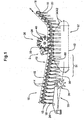
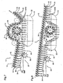
- FIGS. 1 to 8 Examples shown relate to the transport of typically folded in Tabloidform sheets that are individually or superimposed several superimposed by a Greiftransporteurs 12 transported and regardless of their number of sheets / layers for the sake of simplicity as printed product 16 are referred to. It is understood that other flexible sheet products 16 can be transported and processed in this way.
- a stapling device 38 is shown as the work station 2.
- FIG. 1 shows a device 10 according to the invention with a gripping transporter 12, which transports grippers 14 on an endlessly circulating conveying member 15.
- the grippers 14 are equipped with gripping jaws 13, which can be taken in the usual way from a plurality of folded sheet existing printed products 16.
- the printed products 16 are gripped at their respective fold 18 and transported by the grippers 14 in the conveying direction F.
- the fold 18 opposite flower 20 of each printed product 16 is following the gravity down.
- the device 10 according to the invention in this example an opening device 22 with a rotating Auslenkband 24 an adjoining opening wheel 26 and an adjoining the opening wheel 26 coil 30 on.
- a connecting device 36 which in this example is designed as a rotary stapler 38, and a circulation system which has supporting elements 34 at a defined distance from one another at its endlessly circulating conveying member 15 '.
- the stapling device 38 is a conventional rotary stapler which has a plurality of uniformly spaced stapling heads 40 on a carrier plate 39. Such a stapler is z. In WO 02/36474 in Fig. 8 or in EP0606555 and in EP0691215 described.
- the support elements 34 of the circulation 32 have benders 42, which cooperate with the stitching heads 40 of the stapler 38 for carrying out a stapling operation. But it can also be provided Umbieger, which are separated from the support elements and independently of these are movable.
- the feed dog 12 of the inventive device 10 directly from the rotation of a buffer device or a taken over any other conveyor printing products 16 and a workstation 2 fed.
- the printed products may consist of one or more single sheets / layers, and possibly folded in tabloid form and superimposed sheet (not shown here).
- the feed dog 12 transports the printed products 16 into the area of the opening device 22, the flowers of the printed products 16 coming to rest on the circulating deflection belt 24 of the opening device 22, by which they are deflected in the conveying direction F, as shown in FIG Fig. 1 is apparent.
- the subsequent opening wheel 26 the printed products 16 are opened on the flower side and kept open during further transport in the conveying direction F on the helix 30.
- the opened printed products 16 are deposited on the support elements 34 of the circulation 32.
- the grippers 14 are not actively opened but remain closed and the support elements 34 penetrate against the clamping action of the gripper jaws 13 between the gripping jaws 13 a.
- the distances between the grippers 14 on the feed dog 12 and the distances of the support elements 34 of the circulation 32 and their speed are matched accordingly, so that a problem-free assignment of the gripper 14 - and with them the printed products 16 - can be done to the support members 34 and the gripper 14 can run with the support elements 34 in the conveying direction F substantially synchronously.
- a Staple stitching wherein the Umbieger 42 integrated in the support elements 34 ensure the closing of the introduced through the stitching heads 40 in the printed products 16 wire staples. It is understood that the arrangement of the stitching heads on the support disk 39 of the rotary stapler 38 and the rotational speed of the support disk 39 are matched to the distances between the grippers 14 and the support elements 34 and the conveying speed in the direction F.
- benders are not integrated in the support elements 34, they are fed separately to the printing products 16 for closing the staples and, if necessary, carried along with them over a corresponding section of the movement path of the printed products 16 so that a qualitatively demanding stapling can take place.
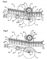
- FIGS. 2 and 3 is a further embodiment of the inventive device 10 is shown, which essentially of the embodiment of Fig. 1 equivalent.
- the support elements 34 are not arranged in a circuit 32 on an endlessly circulating conveyor member 15 ', but they are moved in a wheel-shaped arrangement 44 about a central axis of rotation B on a circular path K.
- the support members 34 may be formed in the form of known saddles or pads or only by appropriately stable trained bender (see. FIGS. 9 and 10 ). The same applies to the support elements 34 from the embodiment of Fig. 1 , The inventive method as described above in connection with the embodiment of Fig. 1 has been described, runs in the Fig. 2 shown analogously from.
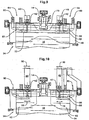
- FIG Fig. 3 is shown.
- the stapling device 38 is lifted pneumatically or hydraulically (arrow H), while the wheel-shaped arrangement 44 and the opening device 22 are pivoted down about the axis of rotation A and thus removed from the transport path (arrow S).
- Opening device 22 and wheel-shaped assembly 44 are arranged on a common machine frame (not shown), which is mounted pivotably about the axis A. It is understood that depending on space and a lateral pivoting or pivoting in any other direction from the transport is also possible.
- a pneumatic or hydraulic lifting and lowering of the stapler 38 may be provided. It is also conceivable lifting or lowering electrically to accomplish. Likewise, it is conceivable to pivot the stapler 38 by such electrical, pneumatic or hydraulic means, as well as to open or lower the opening device 22 and the wheel-shaped arrangement 44 instead of pivoting it.
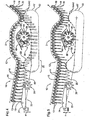
- FIG. 4 5 . 7 and 8 Further embodiments of the inventive device 10 and the inventive method are shown, which differ from the embodiments in the Fig. 1 to 3 essentially differ in that the gripper 14 of the conveyor 12 are opened in the assignment to the support members 34, the printed products 16 are deposited on the support members 34 and the grippers 14 then away from the printed products 16 and the support members 34 via the connecting device 36 away become. Behind the stapler 38, the grippers 14 of the same transporter 12 are again brought together with the now stapled printed products 16 on the support members 34. The grippers 14 of the same transporter 12 grab the now stapled supported by the support members 34 printed products 16 and promote them in the direction F on.
- the gripper 14 of the transporter 12 which has deposited a printed product 16A on a support element 34, to also grasp this printed product 16A after the stitching station 38, or else for this gripper 14 to grip another printed product 16B , Via a control unit (not shown) of Vorrichtug10 invention, the logical assignment of the gripper 14 of the carrier 12 to the coming out of the workstation 2 printed products and in these examples so to the Support elements 34 of the circulation 32 or a wheel-shaped arrangement 44 made.
- the upper strand 50 gives way in Fig. 4 downstream of the assignment region 31 with respect to the feed dog 12 back, in order to then proceed approximately into a horizontal conveying path in the region of the connecting device 36 and again strive for the return of the printed products 16 to the feed dog 12 downstream of the connecting device 36. In this way, space is created for the connecting device 36 and the transport path of the carrier 12 experiences less large deflections. Unlike the embodiment, as in FIGS.
- the opening device 22, the circulation 32 and the connecting device 36 by lowering (arrow H) move out of the transport path of the printed products 16 when the workstation "Connect on the conveyor" to be disabled.
- the situation with the workstation disabled is in Fig. 5 shown.
- the lowering can be done pneumatically, electrically or hydraulically and for each of these elements individually or via a common machine frame. In this case, in order for the grippers not to deliver the printed products 16 to the support elements 34, it is necessary for the grippers 14 to remain closed.
- the scenery control is adjust accordingly.
- a cover 48 arranged above the connection device 36 prevents complications during the transport of the printed products 16 via the connection device 36.
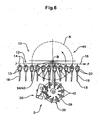
- FIG. 6 a further embodiment of the inventive device 10 is shown, which is substantially that of the FIGS. 2 and 3 equivalent.
- the support members 34 are as in the embodiment of FIGS. 2 and 3 moved in a wheel-shaped arrangement 44 about a central axis of rotation B on a circular path K.
- the printed products 16 are gripped at their respective flower 20 and transported by the grippers 14 via the rotary stapler 38 in the conveying direction F.
- the flower 20 opposite fold 18 of each printed product 16 is following the gravity aligned downwards.
- the support elements 34 of the wheel-shaped arrangement 44 are formed in this example sword and are introduced before the stapling laterally from above between the tabloid sides of the flexible sheet products.
- the opening device 22 is unnecessary. If the stapling operation is not performed, it is possible to shut down the Rotationsheftapparat 38 and / or the wheel-shaped assembly 44 and / or remove from the transport path of the carrier 12.
- Fig. 7 an embodiment is shown which is substantially that of the 4 and 5 corresponds, except that the upper run 50 described in this embodiment in section from the pulleys from an approximately straight line.
- the transport path of the conveyor 12 is configured correspondingly curved.
- the embodiment essentially corresponds again to that of the 4 and 5 , except that here the transport path of the conveyor 12 leads straight across the connecting device 36 away and the geometry of the upper run 50 of the circulation 32 has a correspondingly greater curvature.
- the radius of curvature of the strand 50 can be adapted to the radius which the stitching heads 40 - or in other connecting device 36, such as an ultrasonic device, the sonotrodes, etc. - describe. As a result of this adaptation, the common path of supporting elements and associated stitching heads, sonotrodes etc. is longer, which has an advantageous effect on the quality of the connection.
- FIG. 9 is a support member 34 shown with benders 42 according to the prior art, as in principle, for example, already in the European patent application no. 03025534 , registered on November 7, 2003 with Swiss priority no. 2002 1886/2 of 9 November 2002 in Fig. 7 is shown.
- the support element 34 is configured in the form of a saddle 46, which has a recess 70 in the center, so that the printed products deposited on the saddle 46 can be grasped without problems by a gripper 14 or so that they are never released by the grippers 14 Need to become.
- the benders 42 can be actuated with the aid of a bending device 57 integrated in the support element 34.
- the bending device 57 is arranged on the side opposite the printed products 16 side of the support members 34.
- the support member 34 includes in its lateral end portions 64 of the support members 34 about pivot axes 66 pivotable lever means 68, each with two opposing lever arms, which act on a parallel to the longitudinal extent of the support member 34 extending support member 72.
- pivotable lever means 68 On the support element 72, two mutually spaced Umbieger 42 are supported so that they can cooperate with the stitching heads 40 of an associated stapling device 38. With the aid of stitching heads 40, wire staples are known to be pushed through the printed products 16 lying on the support elements.
- the lever device 68 can be actuated in the manner of a stage (arrow 80) and, when actuated, presses the benders 42 against the stitching heads 40 such that the projecting wire ends are bent over by the benders 42.
- the stapling device 38 and the support members 34 as in Fig. 10 shown according to the invention so developed that now the stapling can be adapted to different paper sizes.
- the saddle 46 instead of the saddle 46, at least two support elements 62 are provided which each stabilize a clincher 42 and provide support for the stored printed products 16.
- the Umbieger 42 by means of a lever device 68 backdrop controlled (arrow 80) operable.
- the lever means 68 are synchronously but individually controlled by scenes during operation.
- the Umbieger 42 with their lever means 68 are arranged on a support (indicated by arrows 60) movable parallel to the longitudinal extent of the support member 34. In order to ensure the interaction with the stitching heads 40, these are likewise movable parallel to the longitudinal extent of the support element 34.
- the stitching heads and the benders are connected to one another in such a way that the respectively associated stitching heads 40 and benders 42 are movable together in parallel to the longitudinal extent of the support element 34.
- the stapling apparatus consists of a rotary stapler 38
- the stapling heads 40 can be displaced, for example, parallel to the longitudinal extent of the supporting element 34, by the carrying discs 39 being displaceable on the axis of the rotary stapler 38 in the axial longitudinal direction.
- a common shift with the Heftgropfen 40 a support plate 39 associated Umbieger 42 is then carried out by connecting the Umbiegers 42 with the support plate 39, for example via a connecting bar (not shown).
- the benders 42 and the stitching heads 40 or support disks 39 can also be movable independently of one another parallel to the longitudinal extent of the support element 34; the stitching heads 40 and the support disks 39 on a first carrier (for example, the axis of the rotary stapler) and the benders 42 on a second carrier, the in Fig. 10 indicated by the arrows 58. It is understood that in such a configuration parallel to the longitudinal extension of the support member 34 does not necessarily have to be worked with two stitches along the fold 18 of a printed product 16. There may be one, two, or more staples, depending on the need and width of the printed product 16 in the longitudinal extension of the support member 34 are made. For this purpose, one, two or more benders 42 with their lever devices 68 and stitching heads 40 or support disks 39 with stitching heads 40 are provided on the supports.
- stapling with staples other methods of connection and operations can be performed on the feed dog.
- an adhesive bond of the printed products 16 can also be produced.
- the inventive device 10 is then instead of a stapling device 38 with a corresponding device for Klebheften, as for example in EP0662440 and EP0628429 disclosed, equipped.
- the connection by means of ultrasound is conceivable at the conveyor.
- a device for ultrasonic bonding as it is eg in EP390733 and EP0390734 instead of using the stapling apparatus 38 or the tacking device.
- the support elements 34 of the circulation 32 and the wheel-shaped arrangement 44 are then designed accordingly.
- Another possible step that can be performed on the feed dog 12 is the insertion.
- stacks that are like in EP1254857 have been formed in printed products 16 are inserted from below by the conveyor via a device, as shown in Fig. 12 and paragraph 45 of EP1254857 is carried away.
- the procedure is then carried out as described in paragraph 46 of the EP1254857 is described, instead of the cover sheet transported by the grippers 14 of the inventive device 16 printed products placed over the ceremoniesstckenden stack and then taken together with the stacks by the gripper 14 of the same carrier 12 again and transported.
- the printed products 16 may for example also have been connected in a previous step already at the feed dog by stitching, gluing or ultrasound.
- the device according to the invention in the area in which is to be inserted, then simply supplemented by a device as in EP1254857 is shown. It is clear that thus supplements and precursors etc. can be inserted without problems.
- Fig. 12 shown device for example, again a folded or more folded in the fold, folded sheet with its fold advancing from below to insert the printed products 16 located in the grippers 14 of the device according to the invention.
- the printed sheets inserted in this way may in turn already be connected to one another by stapling, gluing, etc. After inserting this sheet, it is possible with the same feeders to get to another workstation, in which the inserted sheets are then connected, for example, with the already existing in the grippers 14 printed products 16, whether by ultrasound, gluing or other connection method.
- the feed dog 12 can be guided via workstations following one another in a meaningful manner, the workstations the end of a Schuppestromes, connecting stations (stapling, gluing, ultrasound, etc.), the end of a collection or insertion, a device according to FIG. 12, EP1254857 etc. can be.
- the workstations for example, by lowering, lifting, pivoting from the transport removable and the support elements in the circulations or in the wheel-shaped arrangements and stapling heads, etc. the paper size are customizable, can be great flexibility in the use of reach entire facility.
Landscapes
- Engineering & Computer Science (AREA)
- Mechanical Engineering (AREA)
- Textile Engineering (AREA)
- Folding Of Thin Sheet-Like Materials, Special Discharging Devices, And Others (AREA)
- Collation Of Sheets And Webs (AREA)
- Feeding Of Articles By Means Other Than Belts Or Rollers (AREA)
- Sewing Machines And Sewing (AREA)
- Treatment Of Fiber Materials (AREA)
- Intermediate Stations On Conveyors (AREA)
- Threshing Machine Elements (AREA)
- General Factory Administration (AREA)
- Packaging Of Special Articles (AREA)
- Auxiliary Devices For And Details Of Packaging Control (AREA)
- Separation, Sorting, Adjustment, Or Bending Of Sheets To Be Conveyed (AREA)
- Supplying Of Containers To The Packaging Station (AREA)
- Attitude Control For Articles On Conveyors (AREA)
- Lining Or Joining Of Plastics Or The Like (AREA)
Claims (13)
- Procédé de convoyage et de traitement éventuel de produits souples de configuration plane, en particulier de produits d'impression, dans lequel lesdits produits souples de configuration plane sont acheminés, à l'aide d'un convoyeur, vers un poste de travail et sont de nouveau extraits dudit poste de travail, à l'aide dudit convoyeur, caractérisé par le fait que le convoyeur est un convoyeur de préhension et que le poste de travail (2) est extrait en souplesse du trajet de convoyage des produits d'impression (16), puis réinséré sur ce dernier, et qu'une assignation logique mutuelle, entre des produits souples (16) de configuration plane et des organes de préhension (14) du convoyeur (12), a respectivement lieu à l'aide d'un système de commande.
- Procédé selon la revendication 1, caractérisé par le fait que le poste de travail (2) est extrait du trajet de convoyage du convoyeur (12) par pivotement, abaissement ou soulèvement, ces mouvements étant de préférence exécutés en mode électrique et/ou hydraulique et/ou pneumatique.
- Procédé selon la revendication 2, caractérisé par le fait que, en présence de postes de travail (2) en plusieurs parties, les parties individuelles du poste de travail (2) sont respectivement extraites du trajet de convoyage ou insérées sur ce dernier par pivotement, abaissement ou soulèvement, lesdites parties individuelles pouvant être animées de mouvements différents.
- Procédé selon l'une des revendications 1 à 3, caractérisé par le fait que le même organe de préhension (14), ayant acheminé un produit souple (16A) de configuration plane vers le poste de travail (2), extrait également dudit poste de travail (2) ce produit souple (16A) de configuration plane.
- Procédé selon l'une des revendications 1 à 4, caractérisé par le fait que l'organe de préhension (14) est guidé conjointement et en synchronisme avec le produit souple (16) de configuration plane, au cours du traitement dudit produit souple (16) de configuration plane dans le poste de travail (2), ledit organe de préhension (14) pouvant être ouvert en vue du traitement, ou pouvant également demeurer fermé.
- Procédé selon l'une des revendications 1 à 5, caractérisé par le fait que l'organe de préhension (14), ayant acheminé un produit souple (16A) de configuration plane vers le poste de travail (2), extrait dudit poste de travail (2) un autre produit souple (16B) de configuration plane.
- Procédé selon l'une des revendications 1 à 6, caractérisé par le fait qu'un appui est conféré par un élément d'appui (34) au produit souple (16) de configuration plane, en vue du traitement.
- Procédé selon l'une des revendications 1 à 7, caractérisé par le fait que les produits souples (16) de configuration plane sont délivrés à plusieurs postes de travail (2) au cours de leur acheminement par le même convoyeur (12), lesdits postes de travail (2) étant agencés en succession, de préférence en aval vis-à-vis du trajet de convoyage du convoyeur (12), ou bien disposés dans des tracés dudit convoyeur (12), parallèles et reliées mutuellement par l'intermédiaire d'aiguillages.
- Dispositif de convoyage et de traitement éventuel de produits souples de configuration plane, équipé d'un convoyeur qui achemine lesdits produits souples de configuration plane vers un poste de travail, et les extrait de nouveau dudit poste de travail, caractérisé par le fait que le convoyeur est un convoyeur de préhension et que le poste de travail (2) peut être extrait en souplesse du trajet de convoyage des produits souples (16) de configuration plane, puis réinséré sur ce dernier,
et qu'un système de commande est prévu à l'aide duquel est garantie, à tout instant, une assignation logique mutuelle entre des produits souples (16) de configuration plane et des organes de préhension (14) du convoyeur (12). - Dispositif selon la revendication 9, caractérisé par le fait que le trajet de convoyage du convoyeur (12) est choisi de façon telle que les organes de préhension (14) dudit convoyeur (12) puissent être guidés conjointement et en synchronisme avec le produit souple (16) de configuration plane, au cours du traitement dudit produit souple (16) de configuration plane, la commande des organes de préhension (14), en particulier une coulisse de commande dédiée auxdits organes de préhension (14), étant réglable de façon variable, dans la zone de traitement, de telle sorte que lesdits organes de préhension (14) puissent être ouverts en vue du traitement des produits souples (16) de configuration plane, ou puissent également demeurer fermés.
- Dispositif selon l'une des revendications 9 à 10, caractérisé par le fait que le convoyeur (12) est respectivement guidé, par son trajet de convoyage, au-dessus du poste de travail (2) ou à travers celui-ci et ledit poste de travail englobant notamment une coiffe (48) .
- Dispositif selon l'une des revendications 9 à 11, caractérisé par la présence, le long du trajet de convoyage du convoyeur (12), de plusieurs postes de travail (2) de préférence agencés en succession, en aval, ou disposés dans des tracés dudit convoyeur (12), parallèles et reliées mutuellement par l'intermédiaire d'aiguillages.
- Dispositif selon l'une des revendications 9 à 12, caractérisé par le fait que les postes de travail se présentent comme des dispositifs de liaison (36) - notamment des appareils de brochage, des systèmes à ultrasons, des dispositifs de brochage par encollage-; et/ou comme des dispositifs d'insertion de produits souples de configuration plane ; et/ou comme l'extrémité d'une piste respective de regroupement ou de brochage par regroupement ; et/ou comme l'extrémité d'une piste d'insertion et/ou de brochage par insertion ; ou bien comme un poste de sectionnement.
Priority Applications (1)
| Application Number | Priority Date | Filing Date | Title |
|---|---|---|---|
| PL05008056T PL1588971T3 (pl) | 2004-04-22 | 2005-04-13 | Sposób i urządzenie do obróbki produktów drukarskich |
Applications Claiming Priority (2)
| Application Number | Priority Date | Filing Date | Title |
|---|---|---|---|
| CH7072004 | 2004-04-22 | ||
| CH7072004 | 2004-04-22 |
Publications (3)
| Publication Number | Publication Date |
|---|---|
| EP1588971A1 EP1588971A1 (fr) | 2005-10-26 |
| EP1588971B1 EP1588971B1 (fr) | 2008-10-01 |
| EP1588971B2 true EP1588971B2 (fr) | 2019-06-19 |
Family
ID=34935098
Family Applications (1)
| Application Number | Title | Priority Date | Filing Date |
|---|---|---|---|
| EP05008056.3A Expired - Lifetime EP1588971B2 (fr) | 2004-04-22 | 2005-04-13 | Procédé et dispositif de traitement de produits imprimés |
Country Status (10)
| Country | Link |
|---|---|
| US (3) | US7591223B2 (fr) |
| EP (1) | EP1588971B2 (fr) |
| AT (1) | ATE409672T1 (fr) |
| AU (1) | AU2007221915B2 (fr) |
| CA (1) | CA2504557C (fr) |
| DE (1) | DE502005005499D1 (fr) |
| DK (1) | DK1588971T3 (fr) |
| ES (1) | ES2310304T3 (fr) |
| PL (1) | PL1588971T3 (fr) |
| RU (1) | RU2397134C2 (fr) |
Families Citing this family (6)
| Publication number | Priority date | Publication date | Assignee | Title |
|---|---|---|---|---|
| DE502005005499D1 (de) * | 2004-04-22 | 2008-11-13 | Ferag Ag | Verfahren und Vorrichtung zum Bearbeiten von Druckereiprodukten |
| EP1683612B1 (fr) * | 2005-01-21 | 2016-08-03 | Ferag AG | Procédé et dispositif pour transporter des produits plats flexibles, et pour les découper au même temps |
| CA2573175A1 (fr) * | 2006-01-13 | 2007-07-13 | Ferag Ag | Methode et installation pour le traitement de produits imprimes en cours de transport |
| CH703248A1 (de) * | 2010-05-31 | 2011-12-15 | Ferag Ag | Vorrichtung und verfahren zum öffnen von druckereiprodukten. |
| ITVR20130138A1 (it) * | 2013-06-12 | 2014-12-13 | Dainese Spa | Dispositivo di protezione personale. |
| WO2020229179A1 (fr) * | 2019-05-15 | 2020-11-19 | Bobst Mex Sa | Dispositif de traitement de feuille |
Citations (5)
| Publication number | Priority date | Publication date | Assignee | Title |
|---|---|---|---|---|
| EP0662440A1 (fr) † | 1994-01-10 | 1995-07-12 | Ferag AG | Dispositif pour l'agrafage par adhésif de produits imprimés |
| EP0686463A1 (fr) † | 1994-06-08 | 1995-12-13 | Ferag AG | Dispositif pour couper des imprimés, notamment des journaux, des magazines ou des brochures, au moins des deux cotés |
| WO1996034724A1 (fr) † | 1995-05-02 | 1996-11-07 | Grapha-Holding Ag | Procede et dispositif pour la manipulation de produits imprimes |
| EP1254857A2 (fr) † | 2001-04-26 | 2002-11-06 | Ferag AG | Dispositif pour assembler des articles plats en piles et pour le traitement ultérieur de la pile |
| EP1310444A1 (fr) † | 2001-11-08 | 2003-05-14 | Grapha-Holding AG | Dispositif d'assemblage par insertion de produits imprimés |
Family Cites Families (29)
| Publication number | Priority date | Publication date | Assignee | Title |
|---|---|---|---|---|
| GB191324207A (en) | 1913-10-25 | 1914-10-26 | Anonima Brevetti Caldaie A Vat | Improvements in Locomotive Steam Engines. |
| US3989239A (en) * | 1971-10-20 | 1976-11-02 | Speco, Inc. | Sheet stacking apparatus |
| CH645074A5 (de) * | 1980-03-11 | 1984-09-14 | Ferag Ag | Verfahren und vorrichtung zum bilden von mehrblaettrigen druckprodukten, insbesondere zeitungen und zeitschriften. |
| CH662987A5 (de) * | 1984-01-26 | 1987-11-13 | Grapha Holding Ag | Sattelheftmaschine. |
| DE3760159D1 (en) * | 1986-02-14 | 1989-06-22 | Ferag Ag | Method and apparatus for the insertion of at least one insert into, preferably, folded printed products |
| NL8701816A (nl) | 1987-08-03 | 1989-03-01 | Philips Nv | Elektrische schakeling die gebruikt kan worden in een a/d-omzetter. |
| US5961758A (en) * | 1989-03-30 | 1999-10-05 | Ferag Ag | Process for manufacturing booklets |
| EP0390733B1 (fr) | 1989-03-30 | 1994-08-10 | Ferag AG | Procédé de reliure de feuilles de papier |
| CA2011479C (fr) | 1989-03-30 | 1999-03-30 | Werner Honegger | Procede de reliure de feuilles de papier |
| US5137409A (en) * | 1989-07-21 | 1992-08-11 | Ferag Ag | Joining together of printed partial products |
| ES2075581T3 (es) * | 1992-01-10 | 1995-10-01 | Ferag Ag | Procedimiento y dispositivo para elaborar articulos de imprenta. |
| DE59305872D1 (de) * | 1993-01-11 | 1997-04-24 | Ferag Ag | Sammelhefter für aus gefalteten Druckbogen bestehende Druckprodukte |
| EP0628429B1 (fr) | 1993-06-11 | 1997-04-23 | Ferag AG | Procédé et dispositif pour relier les feuilles d'un produit imprimé à plusieurs feuilles |
| DE59405899D1 (de) * | 1993-12-21 | 1998-06-10 | Grapha Holding Ag | Verfahren zur Beschickung von zu Druckprodukten gesammelten, mehrblättrigen Druckbogen mit Beilagen |
| ES2121250T3 (es) * | 1994-05-04 | 1998-11-16 | Ferag Ag | Procedimiento para el tratamiento de articulos impresos. |
| DE59500526D1 (de) * | 1994-07-06 | 1997-09-25 | Ferag Ag | Vorrichtung zum Drahtheften von Druckereiprodukten |
| DE19500560A1 (de) * | 1995-01-11 | 1996-07-18 | Kolbus Gmbh & Co Kg | Verfahren zum Transportieren von Druckprodukten zwischen weiterverarbeitenden Buchbindemaschinen und Vorrichtung zur Durchführung des Verfahrens |
| FR2731176B1 (fr) * | 1995-03-02 | 1997-04-30 | Sidel Sa | Installation de fabrication de recipients par soufflage de preformes en matiere plastique |
| US5772391A (en) * | 1995-11-22 | 1998-06-30 | Quipp Systems, Inc. | Stacker for counting and stacking signatures delivered by a gripper conveyor |
| WO1998003420A1 (fr) | 1996-07-19 | 1998-01-29 | Ferag Ag | Dispositif de transport |
| EP1330406B1 (fr) | 2000-11-02 | 2006-08-30 | Ferag AG | Dispositif de traitement de produits imprimes |
| DE50113969D1 (de) * | 2001-03-29 | 2008-06-26 | Grapha Holding Ag | Einrichtung zum Heften des Rückens mit Klammern, von aus gefalzten Druckbogen gebildeten Druckerzeugnissen |
| ATE302154T1 (de) * | 2001-07-30 | 2005-09-15 | Ferag Ag | Verfahren und vorrichtung zum zusammenbringen und gemeinsamen weitertransportieren von flächigen gegenständen |
| ITBO20020480A1 (it) * | 2002-07-23 | 2004-01-23 | Tecnomeccanica Srl | Macchina per formare una busta filtro per contenimento di una sostanza da infusione con accumulo di filo associato alla etichetta di presa |
| US7581724B2 (en) | 2002-11-09 | 2009-09-01 | Ferag Ag | Device for collecting and processing folded printed products |
| UA60258A (uk) * | 2003-07-18 | 2003-09-15 | Михайло Олександрович Єрухімович | Екструдер для переробки термопластів і універсальна модульна лінія для виробництва плівки, гранул і погонажних виробів з термопластів |
| DE502005005499D1 (de) * | 2004-04-22 | 2008-11-13 | Ferag Ag | Verfahren und Vorrichtung zum Bearbeiten von Druckereiprodukten |
| EP1683612B1 (fr) * | 2005-01-21 | 2016-08-03 | Ferag AG | Procédé et dispositif pour transporter des produits plats flexibles, et pour les découper au même temps |
| DE102005046683A1 (de) * | 2005-09-29 | 2007-04-05 | Heidelberger Druckmaschinen Ag | Heftvorrichtung |
-
2005
- 2005-04-13 DE DE502005005499T patent/DE502005005499D1/de not_active Expired - Lifetime
- 2005-04-13 ES ES05008056T patent/ES2310304T3/es not_active Expired - Lifetime
- 2005-04-13 PL PL05008056T patent/PL1588971T3/pl unknown
- 2005-04-13 DK DK05008056T patent/DK1588971T3/da active
- 2005-04-13 AT AT05008056T patent/ATE409672T1/de active
- 2005-04-13 EP EP05008056.3A patent/EP1588971B2/fr not_active Expired - Lifetime
- 2005-04-20 CA CA2504557A patent/CA2504557C/fr not_active Expired - Fee Related
- 2005-04-21 RU RU2005111731/11A patent/RU2397134C2/ru not_active IP Right Cessation
- 2005-04-22 US US11/111,948 patent/US7591223B2/en not_active Expired - Lifetime
-
2007
- 2007-10-10 AU AU2007221915A patent/AU2007221915B2/en not_active Ceased
-
2008
- 2008-03-06 US US12/043,618 patent/US20080149464A1/en not_active Abandoned
-
2011
- 2011-09-23 US US13/243,115 patent/US8342317B2/en not_active Expired - Fee Related
Patent Citations (5)
| Publication number | Priority date | Publication date | Assignee | Title |
|---|---|---|---|---|
| EP0662440A1 (fr) † | 1994-01-10 | 1995-07-12 | Ferag AG | Dispositif pour l'agrafage par adhésif de produits imprimés |
| EP0686463A1 (fr) † | 1994-06-08 | 1995-12-13 | Ferag AG | Dispositif pour couper des imprimés, notamment des journaux, des magazines ou des brochures, au moins des deux cotés |
| WO1996034724A1 (fr) † | 1995-05-02 | 1996-11-07 | Grapha-Holding Ag | Procede et dispositif pour la manipulation de produits imprimes |
| EP1254857A2 (fr) † | 2001-04-26 | 2002-11-06 | Ferag AG | Dispositif pour assembler des articles plats en piles et pour le traitement ultérieur de la pile |
| EP1310444A1 (fr) † | 2001-11-08 | 2003-05-14 | Grapha-Holding AG | Dispositif d'assemblage par insertion de produits imprimés |
Non-Patent Citations (18)
| Title |
|---|
| Arbeitsausweise von Hrn. W. Weibel zu den Arbeiten in Nürnberg † |
| Bestätigungssschreiben von Prinovis vom 290609 † |
| Bestellung des Prospekts V1c vom 250300 † |
| Bestellung vom 07.08.01 † |
| Betriebsanleitung Corona, Titelseite, Seiten 00.01.1-2, 1.1.1-3, 3.20.1- 3.20.3, 5.01.1- 11,5.10.1- 3,8.1.1- 8.1.10, 8.50.1- 10, 11.1.1-6, 11.60.3-5 † |
| 'Corona Klebebinder- Technologie fürs dritte Millennium: flexibel, wirtschaftlich und zuverlässig', Prospekt der Müller Martini Marketing AG, Nummer 0002/R1/0069.1052.70 † |
| Ersatzteilkatalog Corona, Titelseite, Titelrückseite, Seiten 6.1.1, 8.1.1 - 6, 8.50.1, 8.50.2, 8.51.1, 8.52.1-4, 8.60.1-4, 8.61.1, 8.70.1, 11.3.1, 11.3.2 † |
| KIPPHAN, H.: "Handbuch der Printmedien", 2000, SPRINGER VERLAG, ISBN: 3-540-66941-8 † |
| LIEBAU, D. ET AL: "INDUSTRIELLE BUCHBINDEREI", 1997, VERLAG BERUF+SCHULE, ISBN: 3-88013-553-3, article "Buchfertigung (Serie)", pages: 269 - 272 † |
| Newsliner-A Die Hochleistungs-Einsteckanlage für den fortschrittlichen Zeitungsbetrieb, Prospekt der Müller Martini Marketing AG, Nummer 0801/R2/0069.3045.70 † |
| 'panorama' 2/95, Firmenzeitschrift der Einsprechenden Seiten 1, 3, 20, 21, 27 † |
| 'panorama' 4/95, Firmenzeitschrift der Einsprechenden Seiten 1, 3, 9 sowie letzte Seite † |
| Rechnung 90190093 zum Auftrag 323192 vom 120700 † |
| Rechnung vom 280400 zur Bestellung V1d † |
| Rechnung vom 310801 zur Bestellung. † |
| 'Screenshots' von Datenbankauszügen der Einsprechenden † |
| Versandanzeige der Firma Danzas AG † |
| Zeichnung 0167.1377.0 C zum Auftrag 323192 † |
Also Published As
| Publication number | Publication date |
|---|---|
| US20120007303A1 (en) | 2012-01-12 |
| EP1588971A1 (fr) | 2005-10-26 |
| US20050236757A1 (en) | 2005-10-27 |
| PL1588971T3 (pl) | 2009-03-31 |
| EP1588971B1 (fr) | 2008-10-01 |
| ES2310304T3 (es) | 2009-01-01 |
| ATE409672T1 (de) | 2008-10-15 |
| CA2504557A1 (fr) | 2005-10-22 |
| US7591223B2 (en) | 2009-09-22 |
| DE502005005499D1 (de) | 2008-11-13 |
| US8342317B2 (en) | 2013-01-01 |
| RU2397134C2 (ru) | 2010-08-20 |
| RU2005111731A (ru) | 2006-10-27 |
| AU2007221915B2 (en) | 2010-06-03 |
| CA2504557C (fr) | 2011-10-25 |
| DK1588971T3 (da) | 2009-02-09 |
| US20080149464A1 (en) | 2008-06-26 |
| AU2007221915A1 (en) | 2008-05-08 |
Similar Documents
| Publication | Publication Date | Title |
|---|---|---|
| EP3736235A1 (fr) | Dispositif de manipulation de pile de produits pliés, plieuse correspondante, et procédé de transfert de piles de produits | |
| EP0675005B1 (fr) | Dispositif pour la reliure adhésive de produits imprimés | |
| EP2113392A1 (fr) | Reliure par collage destinée au traitement d'un bloc de livre et procédé de reliure par collage | |
| CH667620A5 (de) | Verfahren und vorrichtung zum sammeln von gefalzten druckbogen. | |
| DE19757163A1 (de) | Bogendruckmaschine mit Nachverarbeitungseinheit | |
| EP3450359B1 (fr) | Dispositif et procédé de manipulation d'au moins une rangée de marchandises en mouvement les unes derrière les autres | |
| EP3482892B1 (fr) | Procédure pour l'exécution d'opérations de coupe de bords de format ouverts d'un produit imprimé | |
| DE19839312A1 (de) | Vorrichtung und Verfahren für das kombinierte Zusammentragen und Binden von bogenförmigen Produkten | |
| DE2508745C2 (de) | Vorrichtung zum Aufstauen vereinzelt mittels einer Transportvorrichtung zugeförderter Papierbögen zu Stapeln und zum Weitertransportieren dieser Stapel | |
| EP0897890B1 (fr) | Procédé et dispositif pour produire un courant de produits tournés avec une pince de préhension de coin | |
| EP1588971B2 (fr) | Procédé et dispositif de traitement de produits imprimés | |
| EP0712736B1 (fr) | Méthode pour la fabrication de livres, brochures ou similaires reliés par adhésif | |
| EP0659586B1 (fr) | Procédé pour délivrer un ensemble de feuilles imprimées avec des encarts | |
| CH659637A5 (de) | Verfahren und vorrichtung zum kontinuierlichen beladen von einer anzahl blatt-foerderer. | |
| EP1334938A1 (fr) | Dispositif pour produire des produits imprimés reliés | |
| EP0529204A1 (fr) | Appareil pour transférer des plaques vers une machine de thermoformage | |
| EP0514783A1 (fr) | Dispositif pour transporter des piles de feuilles en papier | |
| EP0169489B1 (fr) | Dispositif pour plier et transformer des imprimés | |
| DE1436064C3 (de) | Vorrichtung zum Zusammentragen gefalzter Bogen zu einem Buchblock | |
| EP0970820A2 (fr) | Dispositif de transport | |
| EP2181953B1 (fr) | Dispositif d'introduction de feuilles d'impression pour la fabrication de blocs de livres, de livres ou de produits d'impression analogues | |
| EP1443006B1 (fr) | Procédé pour rompre et ventiler une pile des feuilles, en particulier une pile des feuilles de papier | |
| DE10220550A1 (de) | Verfahren und Vorrichtung zur Weiterverarbeitung von Druckzwischenprodukten | |
| WO2003089349A1 (fr) | Dispositif servant a prelever individuellement et ouvrir des sacs empiles dans des chargeurs | |
| EP2383214A1 (fr) | Dispositif d'assemblage |
Legal Events
| Date | Code | Title | Description |
|---|---|---|---|
| PUAI | Public reference made under article 153(3) epc to a published international application that has entered the european phase |
Free format text: ORIGINAL CODE: 0009012 |
|
| AK | Designated contracting states |
Kind code of ref document: A1 Designated state(s): AT BE BG CH CY CZ DE DK EE ES FI FR GB GR HU IE IS IT LI LT LU MC NL PL PT RO SE SI SK TR |
|
| AX | Request for extension of the european patent |
Extension state: AL BA HR LV MK YU |
|
| 17P | Request for examination filed |
Effective date: 20060426 |
|
| AKX | Designation fees paid |
Designated state(s): AT BE BG CH CY CZ DE DK EE ES FI FR GB GR HU IE IS IT LI LT LU MC NL PL PT RO SE SI SK TR |
|
| GRAP | Despatch of communication of intention to grant a patent |
Free format text: ORIGINAL CODE: EPIDOSNIGR1 |
|
| GRAS | Grant fee paid |
Free format text: ORIGINAL CODE: EPIDOSNIGR3 |
|
| GRAA | (expected) grant |
Free format text: ORIGINAL CODE: 0009210 |
|
| AK | Designated contracting states |
Kind code of ref document: B1 Designated state(s): AT BE BG CH CY CZ DE DK EE ES FI FR GB GR HU IE IS IT LI LT LU MC NL PL PT RO SE SI SK TR |
|
| REG | Reference to a national code |
Ref country code: GB Ref legal event code: FG4D Free format text: NOT ENGLISH |
|
| REG | Reference to a national code |
Ref country code: CH Ref legal event code: EP |
|
| REG | Reference to a national code |
Ref country code: CH Ref legal event code: NV Representative=s name: RENTSCH & PARTNER |
|
| REG | Reference to a national code |
Ref country code: IE Ref legal event code: FG4D Free format text: LANGUAGE OF EP DOCUMENT: GERMAN |
|
| REF | Corresponds to: |
Ref document number: 502005005499 Country of ref document: DE Date of ref document: 20081113 Kind code of ref document: P |
|
| REG | Reference to a national code |
Ref country code: ES Ref legal event code: FG2A Ref document number: 2310304 Country of ref document: ES Kind code of ref document: T3 |
|
| REG | Reference to a national code |
Ref country code: SE Ref legal event code: TRGR |
|
| REG | Reference to a national code |
Ref country code: DK Ref legal event code: T3 |
|
| PG25 | Lapsed in a contracting state [announced via postgrant information from national office to epo] |
Ref country code: SI Free format text: LAPSE BECAUSE OF FAILURE TO SUBMIT A TRANSLATION OF THE DESCRIPTION OR TO PAY THE FEE WITHIN THE PRESCRIBED TIME-LIMIT Effective date: 20081001 |
|
| REG | Reference to a national code |
Ref country code: PL Ref legal event code: T3 |
|
| REG | Reference to a national code |
Ref country code: IE Ref legal event code: FD4D |
|
| PG25 | Lapsed in a contracting state [announced via postgrant information from national office to epo] |
Ref country code: BG Free format text: LAPSE BECAUSE OF FAILURE TO SUBMIT A TRANSLATION OF THE DESCRIPTION OR TO PAY THE FEE WITHIN THE PRESCRIBED TIME-LIMIT Effective date: 20090101 Ref country code: LT Free format text: LAPSE BECAUSE OF FAILURE TO SUBMIT A TRANSLATION OF THE DESCRIPTION OR TO PAY THE FEE WITHIN THE PRESCRIBED TIME-LIMIT Effective date: 20081001 |
|
| PG25 | Lapsed in a contracting state [announced via postgrant information from national office to epo] |
Ref country code: PT Free format text: LAPSE BECAUSE OF FAILURE TO SUBMIT A TRANSLATION OF THE DESCRIPTION OR TO PAY THE FEE WITHIN THE PRESCRIBED TIME-LIMIT Effective date: 20090302 Ref country code: IS Free format text: LAPSE BECAUSE OF FAILURE TO SUBMIT A TRANSLATION OF THE DESCRIPTION OR TO PAY THE FEE WITHIN THE PRESCRIBED TIME-LIMIT Effective date: 20090201 |
|
| PLBI | Opposition filed |
Free format text: ORIGINAL CODE: 0009260 |
|
| PG25 | Lapsed in a contracting state [announced via postgrant information from national office to epo] |
Ref country code: IE Free format text: LAPSE BECAUSE OF FAILURE TO SUBMIT A TRANSLATION OF THE DESCRIPTION OR TO PAY THE FEE WITHIN THE PRESCRIBED TIME-LIMIT Effective date: 20081001 Ref country code: EE Free format text: LAPSE BECAUSE OF FAILURE TO SUBMIT A TRANSLATION OF THE DESCRIPTION OR TO PAY THE FEE WITHIN THE PRESCRIBED TIME-LIMIT Effective date: 20081001 Ref country code: RO Free format text: LAPSE BECAUSE OF FAILURE TO SUBMIT A TRANSLATION OF THE DESCRIPTION OR TO PAY THE FEE WITHIN THE PRESCRIBED TIME-LIMIT Effective date: 20081001 |
|
| PLAX | Notice of opposition and request to file observation + time limit sent |
Free format text: ORIGINAL CODE: EPIDOSNOBS2 |
|
| 26 | Opposition filed |
Opponent name: MUELLER MARTINI HOLDING AG Effective date: 20090630 |
|
| PG25 | Lapsed in a contracting state [announced via postgrant information from national office to epo] |
Ref country code: SK Free format text: LAPSE BECAUSE OF FAILURE TO SUBMIT A TRANSLATION OF THE DESCRIPTION OR TO PAY THE FEE WITHIN THE PRESCRIBED TIME-LIMIT Effective date: 20081001 |
|
| NLR1 | Nl: opposition has been filed with the epo |
Opponent name: MUELLER MARTINI HOLDING AG |
|
| BERE | Be: lapsed |
Owner name: FERAG AG Effective date: 20090430 |
|
| PLAF | Information modified related to communication of a notice of opposition and request to file observations + time limit |
Free format text: ORIGINAL CODE: EPIDOSCOBS2 |
|
| PLBB | Reply of patent proprietor to notice(s) of opposition received |
Free format text: ORIGINAL CODE: EPIDOSNOBS3 |
|
| PG25 | Lapsed in a contracting state [announced via postgrant information from national office to epo] |
Ref country code: MC Free format text: LAPSE BECAUSE OF NON-PAYMENT OF DUE FEES Effective date: 20090430 |
|
| PG25 | Lapsed in a contracting state [announced via postgrant information from national office to epo] |
Ref country code: BE Free format text: LAPSE BECAUSE OF NON-PAYMENT OF DUE FEES Effective date: 20090430 |
|
| PG25 | Lapsed in a contracting state [announced via postgrant information from national office to epo] |
Ref country code: GR Free format text: LAPSE BECAUSE OF FAILURE TO SUBMIT A TRANSLATION OF THE DESCRIPTION OR TO PAY THE FEE WITHIN THE PRESCRIBED TIME-LIMIT Effective date: 20090102 |
|
| PG25 | Lapsed in a contracting state [announced via postgrant information from national office to epo] |
Ref country code: LU Free format text: LAPSE BECAUSE OF NON-PAYMENT OF DUE FEES Effective date: 20090413 |
|
| PG25 | Lapsed in a contracting state [announced via postgrant information from national office to epo] |
Ref country code: HU Free format text: LAPSE BECAUSE OF FAILURE TO SUBMIT A TRANSLATION OF THE DESCRIPTION OR TO PAY THE FEE WITHIN THE PRESCRIBED TIME-LIMIT Effective date: 20090402 |
|
| REG | Reference to a national code |
Ref country code: CH Ref legal event code: PFA Owner name: FERAG AG Free format text: FERAG AG#ZUERICHSTRASSE 74#8340 HINWIL (CH) -TRANSFER TO- FERAG AG#ZUERICHSTRASSE 74#8340 HINWIL (CH) |
|
| PG25 | Lapsed in a contracting state [announced via postgrant information from national office to epo] |
Ref country code: TR Free format text: LAPSE BECAUSE OF FAILURE TO SUBMIT A TRANSLATION OF THE DESCRIPTION OR TO PAY THE FEE WITHIN THE PRESCRIBED TIME-LIMIT Effective date: 20081001 |
|
| PG25 | Lapsed in a contracting state [announced via postgrant information from national office to epo] |
Ref country code: CY Free format text: LAPSE BECAUSE OF FAILURE TO SUBMIT A TRANSLATION OF THE DESCRIPTION OR TO PAY THE FEE WITHIN THE PRESCRIBED TIME-LIMIT Effective date: 20081001 |
|
| PLAY | Examination report in opposition despatched + time limit |
Free format text: ORIGINAL CODE: EPIDOSNORE2 |
|
| PLBC | Reply to examination report in opposition received |
Free format text: ORIGINAL CODE: EPIDOSNORE3 |
|
| REG | Reference to a national code |
Ref country code: FR Ref legal event code: PLFP Year of fee payment: 12 |
|
| APBM | Appeal reference recorded |
Free format text: ORIGINAL CODE: EPIDOSNREFNO |
|
| APBP | Date of receipt of notice of appeal recorded |
Free format text: ORIGINAL CODE: EPIDOSNNOA2O |
|
| APAH | Appeal reference modified |
Free format text: ORIGINAL CODE: EPIDOSCREFNO |
|
| APBM | Appeal reference recorded |
Free format text: ORIGINAL CODE: EPIDOSNREFNO |
|
| APBP | Date of receipt of notice of appeal recorded |
Free format text: ORIGINAL CODE: EPIDOSNNOA2O |
|
| REG | Reference to a national code |
Ref country code: FR Ref legal event code: PLFP Year of fee payment: 13 |
|
| PGFP | Annual fee paid to national office [announced via postgrant information from national office to epo] |
Ref country code: PL Payment date: 20170323 Year of fee payment: 13 |
|
| APBQ | Date of receipt of statement of grounds of appeal recorded |
Free format text: ORIGINAL CODE: EPIDOSNNOA3O |
|
| APBQ | Date of receipt of statement of grounds of appeal recorded |
Free format text: ORIGINAL CODE: EPIDOSNNOA3O |
|
| PGFP | Annual fee paid to national office [announced via postgrant information from national office to epo] |
Ref country code: NL Payment date: 20170419 Year of fee payment: 13 |
|
| PGFP | Annual fee paid to national office [announced via postgrant information from national office to epo] |
Ref country code: IT Payment date: 20170925 Year of fee payment: 14 Ref country code: DK Payment date: 20170419 Year of fee payment: 13 Ref country code: FR Payment date: 20170419 Year of fee payment: 13 |
|
| PGFP | Annual fee paid to national office [announced via postgrant information from national office to epo] |
Ref country code: ES Payment date: 20170510 Year of fee payment: 13 Ref country code: FI Payment date: 20170412 Year of fee payment: 13 Ref country code: SE Payment date: 20170419 Year of fee payment: 13 |
|
| APBU | Appeal procedure closed |
Free format text: ORIGINAL CODE: EPIDOSNNOA9O |
|
| REG | Reference to a national code |
Ref country code: DK Ref legal event code: EBP Effective date: 20180430 |
|
| REG | Reference to a national code |
Ref country code: SE Ref legal event code: EUG |
|
| REG | Reference to a national code |
Ref country code: NL Ref legal event code: MM Effective date: 20180501 |
|
| PG25 | Lapsed in a contracting state [announced via postgrant information from national office to epo] |
Ref country code: CZ Free format text: LAPSE BECAUSE OF NON-PAYMENT OF DUE FEES Effective date: 20180413 Ref country code: SE Free format text: LAPSE BECAUSE OF NON-PAYMENT OF DUE FEES Effective date: 20180414 Ref country code: FI Free format text: LAPSE BECAUSE OF NON-PAYMENT OF DUE FEES Effective date: 20180413 Ref country code: NL Free format text: LAPSE BECAUSE OF NON-PAYMENT OF DUE FEES Effective date: 20180501 |
|
| PG25 | Lapsed in a contracting state [announced via postgrant information from national office to epo] |
Ref country code: FR Free format text: LAPSE BECAUSE OF NON-PAYMENT OF DUE FEES Effective date: 20180430 Ref country code: IT Free format text: LAPSE BECAUSE OF NON-PAYMENT OF DUE FEES Effective date: 20180413 |
|
| PUAH | Patent maintained in amended form |
Free format text: ORIGINAL CODE: 0009272 |
|
| STAA | Information on the status of an ep patent application or granted ep patent |
Free format text: STATUS: PATENT MAINTAINED AS AMENDED |
|
| PG25 | Lapsed in a contracting state [announced via postgrant information from national office to epo] |
Ref country code: DK Free format text: LAPSE BECAUSE OF NON-PAYMENT OF DUE FEES Effective date: 20180430 |
|
| REG | Reference to a national code |
Ref country code: CH Ref legal event code: AELC |
|
| 27A | Patent maintained in amended form |
Effective date: 20190619 |
|
| AK | Designated contracting states |
Kind code of ref document: B2 Designated state(s): AT BE BG CH CY CZ DE DK EE ES FI FR GB GR HU IE IS IT LI LT LU MC NL PL PT RO SE SI SK TR |
|
| REG | Reference to a national code |
Ref country code: DE Ref legal event code: R102 Ref document number: 502005005499 Country of ref document: DE |
|
| PG25 | Lapsed in a contracting state [announced via postgrant information from national office to epo] |
Ref country code: PL Free format text: LAPSE BECAUSE OF NON-PAYMENT OF DUE FEES Effective date: 20180413 |
|
| PG25 | Lapsed in a contracting state [announced via postgrant information from national office to epo] |
Ref country code: ES Free format text: LAPSE BECAUSE OF FAILURE TO SUBMIT A TRANSLATION OF THE DESCRIPTION OR TO PAY THE FEE WITHIN THE PRESCRIBED TIME-LIMIT Effective date: 20190619 |
|
| REG | Reference to a national code |
Ref country code: ES Ref legal event code: FD2A Effective date: 20200420 |
|
| PG25 | Lapsed in a contracting state [announced via postgrant information from national office to epo] |
Ref country code: ES Free format text: LAPSE BECAUSE OF FAILURE TO SUBMIT A TRANSLATION OF THE DESCRIPTION OR TO PAY THE FEE WITHIN THE PRESCRIBED TIME-LIMIT Effective date: 20180414 |
|
| PGFP | Annual fee paid to national office [announced via postgrant information from national office to epo] |
Ref country code: GB Payment date: 20220420 Year of fee payment: 18 Ref country code: DE Payment date: 20220420 Year of fee payment: 18 |
|
| PGFP | Annual fee paid to national office [announced via postgrant information from national office to epo] |
Ref country code: CH Payment date: 20220622 Year of fee payment: 18 Ref country code: AT Payment date: 20220421 Year of fee payment: 18 |
|
| REG | Reference to a national code |
Ref country code: DE Ref legal event code: R119 Ref document number: 502005005499 Country of ref document: DE |
|
| REG | Reference to a national code |
Ref country code: CH Ref legal event code: PL |
|
| REG | Reference to a national code |
Ref country code: AT Ref legal event code: MM01 Ref document number: 409672 Country of ref document: AT Kind code of ref document: T Effective date: 20230413 |
|
| GBPC | Gb: european patent ceased through non-payment of renewal fee |
Effective date: 20230413 |
|
| PG25 | Lapsed in a contracting state [announced via postgrant information from national office to epo] |
Ref country code: GB Free format text: LAPSE BECAUSE OF NON-PAYMENT OF DUE FEES Effective date: 20230413 |
|
| PG25 | Lapsed in a contracting state [announced via postgrant information from national office to epo] |
Ref country code: LI Free format text: LAPSE BECAUSE OF NON-PAYMENT OF DUE FEES Effective date: 20230430 Ref country code: GB Free format text: LAPSE BECAUSE OF NON-PAYMENT OF DUE FEES Effective date: 20230413 Ref country code: DE Free format text: LAPSE BECAUSE OF NON-PAYMENT OF DUE FEES Effective date: 20231103 Ref country code: CH Free format text: LAPSE BECAUSE OF NON-PAYMENT OF DUE FEES Effective date: 20230430 Ref country code: AT Free format text: LAPSE BECAUSE OF NON-PAYMENT OF DUE FEES Effective date: 20230413 |