EP0970820A2 - Dispositif de transport - Google Patents
Dispositif de transport Download PDFInfo
- Publication number
- EP0970820A2 EP0970820A2 EP99111954A EP99111954A EP0970820A2 EP 0970820 A2 EP0970820 A2 EP 0970820A2 EP 99111954 A EP99111954 A EP 99111954A EP 99111954 A EP99111954 A EP 99111954A EP 0970820 A2 EP0970820 A2 EP 0970820A2
- Authority
- EP
- European Patent Office
- Prior art keywords
- transport device
- book
- signatures
- transport
- belt
- Prior art date
- Legal status (The legal status is an assumption and is not a legal conclusion. Google has not performed a legal analysis and makes no representation as to the accuracy of the status listed.)
- Granted
Links
Images

Classifications
-
- B—PERFORMING OPERATIONS; TRANSPORTING
- B42—BOOKBINDING; ALBUMS; FILES; SPECIAL PRINTED MATTER
- B42C—BOOKBINDING
- B42C19/00—Multi-step processes for making books
- B42C19/08—Conveying between operating stations in machines
-
- B—PERFORMING OPERATIONS; TRANSPORTING
- B65—CONVEYING; PACKING; STORING; HANDLING THIN OR FILAMENTARY MATERIAL
- B65H—HANDLING THIN OR FILAMENTARY MATERIAL, e.g. SHEETS, WEBS, CABLES
- B65H29/00—Delivering or advancing articles from machines; Advancing articles to or into piles
- B65H29/12—Delivering or advancing articles from machines; Advancing articles to or into piles by means of the nip between two, or between two sets of, moving tapes or bands or rollers
-
- B—PERFORMING OPERATIONS; TRANSPORTING
- B65—CONVEYING; PACKING; STORING; HANDLING THIN OR FILAMENTARY MATERIAL
- B65H—HANDLING THIN OR FILAMENTARY MATERIAL, e.g. SHEETS, WEBS, CABLES
- B65H5/00—Feeding articles separated from piles; Feeding articles to machines
- B65H5/32—Saddle-like members over which partially-unfolded sheets or signatures are fed to signature-gathering, stitching, or like machines
-
- B—PERFORMING OPERATIONS; TRANSPORTING
- B65—CONVEYING; PACKING; STORING; HANDLING THIN OR FILAMENTARY MATERIAL
- B65H—HANDLING THIN OR FILAMENTARY MATERIAL, e.g. SHEETS, WEBS, CABLES
- B65H2301/00—Handling processes for sheets or webs
- B65H2301/40—Type of handling process
- B65H2301/44—Moving, forwarding, guiding material
- B65H2301/447—Moving, forwarding, guiding material transferring material between transport devices
- B65H2301/4474—Pair of cooperating moving elements as rollers, belts forming nip into which material is transported
-
- B—PERFORMING OPERATIONS; TRANSPORTING
- B65—CONVEYING; PACKING; STORING; HANDLING THIN OR FILAMENTARY MATERIAL
- B65H—HANDLING THIN OR FILAMENTARY MATERIAL, e.g. SHEETS, WEBS, CABLES
- B65H2301/00—Handling processes for sheets or webs
- B65H2301/40—Type of handling process
- B65H2301/44—Moving, forwarding, guiding material
- B65H2301/447—Moving, forwarding, guiding material transferring material between transport devices
- B65H2301/4479—Saddle conveyor with saddle member extending in transport direction
Definitions
- the present invention relates to a transport device, in particular a Transport device, the signatures, which are on a saddle chain of a saddle stitcher move, transported away from the saddle chain.
- the collated signatures from one Saddle chain to a processing station passes the Signatures of the stapling station fed via a pendulum arrangement.
- the bundle collated signatures is taken up by the pendulum arrangement to which Stapling station moved and released there.
- the pendulum arrangement then moves back and takes the following bundle of signatures to the stapling station feed, while at the same time the previously handed over to the stapling station and meanwhile stapled bundles are gripped again and fed to the delivery.
- a Transfer device and a stapling machine of this type are in US 3,317,026 described.
- the known transport systems for saddle stitchers include a so-called Pendulum gripper system, which has a number of grippers arranged in a row, the when closed, press against the outside of the book. These grippers work on a counter pressure rod on the inside of the book in a way that a Half of the book is held between the grippers and the platen.
- the Grippers open, hand the book over to the stapling station and move back again in the closed state.
- the grippers close around on the Transport device moving books when moving forward again put. In this way, the books are accelerated away from the saddle chain and into stopped at a stapling position.
- the entire gripper and counter pressure rod arrangement is arranged on a linear sliding surface and is back and forth by a crank mechanism emotional.
- the present invention relates in particular to a transport device which is suitable for moving collated signatures or bundles of signatures to be transported from a saddle chain to a processing station.
- a variety collected signatures which are arranged one above the other on a saddle chain and have reached a position at which they are to be fed to a processing station, are transferred to the transport device, which takes them from the saddle chain to the Processing station moves.
- the transport device comprises a first pair of Funding means, which has a first and a second conveying element, which are at a distance are arranged to each other and to each other. While the signatures on the Saddle chain are arranged, one side of the signatures moves into the space between the first and the second conveyor element, and the signature bundle is on captured in this way by the transport device.
- the signatures are between the gripped first and second conveyor element and accelerated away from the saddle chain, by accelerating the first pair of grants.
- the signatures then become transported to the processing station.
- the funding elements are from a Drive device driven, which is controlled by a control device, which the drive device is coupled.
- On a corresponding signal from the control device are the opposite conveyor elements from the drive device braked and stopped when the signature bundle is in the correct position at the Processing station has reached.
- the conveyor elements can open at this point and the signatures for further processing, for example on a wire stitching device to hand over.
- the conveyor elements can if necessary, close again and the bundle of signatures away from the processing station accelerate and to another processing station or in a transfer position convey the signatures for final processing to another Conveyor device will be handed over.
- the Signatures released and sent to a last processing station, e.g. B. a trimmer, to hand over.
- Each conveying element of the pair of conveying means preferably comprises belt devices for transporting signatures.
- the tape device which preferably consists of a pair of bands that can move faster than the saddle chain, becomes a first Bundle of signatures reaching the conveyor belt device away from the chain accelerated and stopped in a processing position in which the belts open can, while a subsequent second bundle of signatures continues with constant Speed moved slowly on the saddle chain.
- the first Processing process at the first processing station closes the belt pair again and grabs the first bundle of collated signatures on the first Processing station and the subsequent second bundle gathered Signatures, which is now a position in the space between the Has reached belt devices.
- the first bundle of signatures is placed in a transfer position moves while the second bundle of signatures to the first processing station is transported.
- signatures are on a moving saddle chain hanging together, with the first page of the signatures on one side the saddle chain and the second side of the signatures is on the other side of the Saddle chain is located.
- the drive device sets this to a signal from the control device Pair of bands in motion.
- the signatures Once the tapes are moving the speed Have reached the saddle chain, the signatures enter the space between the Bands, at which point there is preferably no difference between the Speed of the saddle chain and the speed of the belts. Thereupon close the bands, d. H. they capture the bundle of signatures and accelerate them Signatures away from the saddle chain. Accordingly, the acceleration of the tapes and the preceding continuous movement of the signatures in time be coordinated.
- the control device sends the signal in time Accelerate the belts must be given the right time from the Speed of the moving saddle chain and the acceleration of the belts is dependent.
- the bundle of signatures is then accelerated away from the saddle chain.
- the drive slows down the belts, thereby the bundle of signatures slowed down accordingly and finally at a predetermined Breakpoint is stopped at which the machining process, for. B. stapling, should be made.
- the tapes preferably open, so the signatures can be positioned exactly on the guide rail before stapling. After the stapling process is complete, the tapes close around the stapled ones Signatures that can now be considered a book and speed up the book by the stapling position away.
- Fig. 1 shows a schematic side view of the transport device according to the present invention.
- the books A, B, C and D shown in Fig. 1 consist of a Large number of signatures collected on a saddle chain.
- Books A and B move on the saddle chain 1 in the direction of the arrow and are thereby on the Saddle chain 1 arranged carriers 2, which is a common movement of the books ensure according to the movement of the saddle chain, in a predetermined position held.
- Books A, B move on the saddle chain preferably with constant Speed.
- the signatures of each book hang on the saddle chain and comprise two pages.
- the first page 5 of the book hangs on one side of the chain 1, and the second side 6 hangs on the other side of the chain 1, ie opposite the first side.
- Book B has reached position 20 on the transport device in which it is from chain 1 to be transported away to a processing station 30.
- the transport device 7, which is arranged on the first page 5 of the book, comprises an outer conveyor belt 7 and an inner conveyor belt 8 (Fig. 2).
- the outer and inner conveyor belt are arranged opposite each other and can leave a space between each other form, whose width is smaller than the thickness of one side 5 of the to be transported Signature bundle, preferably smaller than the thickness of a signature of the Signature bundle. If the saddle chain 1 moves further, the book B is in the Gap between the outer and inner conveyor belts 7, 8 on the first Page 5 out.
- the cross section in FIG. 2 shows an inner conveyor belt 8, an outer conveyor belt 7 and a wire stapler 9.
- the inner band 8 and the outer band 7 are related to the normal direction 10 of the wire stitching device 9, which is generally parallel to the Saddle chain 1 is arranged at an angle ⁇ , where ⁇ between 90 ° and 180 °, but preferably between 140 ° and 170 °.
- the inner band 8 and that outer band 7 are arranged parallel to each other, the inner sides of the band one on top of the other are directed to.
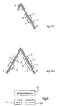
- FIG. 3 shows a partial, schematic representation of the transport device according to FIG of the present invention.
- the first page 5 one of a variety of signatures existing book A hangs on the guide rail 9, the book A a first (left) side 5 and a second (right) side 6 comprises, each on different sides the guide rail 9 are arranged.
- the first band 7 is opposite arranged the second band 8, the surfaces of the bands 7, 8 towards each other are directed and the bands are arranged at a distance from each other that is small enough is to keep the book A in the space.
- the bands 7, 8 are parallel to the direction of movement and with respect to the normal direction 10 of the guide rail 9 (Fig. 2) arranged at an angle ⁇ , the normal direction 10 parallel to the The normal direction of the saddle chain runs.
- the bands 7, 8 preferably have the same Width, but can also be of different widths, as shown in Fig. 3.
- FIG. 4a and 4b show the two different arrangements described above in detail.
- the first page 5 of the book A is held between an outer band 7 and an inner band 8.
- the width of the bands is essentially the same.
- the tapes can also have different dimensions, particularly with regard to their width.
- Fig. 4b z. B. the width W 1 of the belt 7 smaller than the width W 2 of the belt 8.
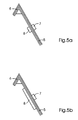
- 5a to 5d show a schematic cross section along the line III-III in FIG. 4b for different band arrangements.
- 5a the inner band 8 and the outer band 7 essentially the same size and are opposite to each other and not offset arranged to each other while holding a book A.
- 5b is the width of the Band 7 smaller than the width of the band 8, as already shown in Fig. 4b.
- 5c is a further band arrangement is shown, in which the outer band device two bands 7, 7 ' comprises and the inner band arrangement comprises two bands 8, 8 ', the Belt devices that grip a page 5 of a book between them face to face and are staggered.
- the outer band device on one side 5 comprises three bands 7, 7 ', 7' ', the are arranged opposite two bands 8, 8 ', which are wider than the bands 7, 7', 7 ''.
- the Page 5 is between the first group of belt devices 7, 7 ', 7' 'and the second Group of belt devices 8, 8 'gripped.
- All of the belt arrangements described here can be combined with one another as desired to optimize the reliability of the transport device. As before described, it is in book transport at high speeds, such as Speeds of more than 12,000 pieces per hour, a great advantage, two pairs To use belt devices. As shown in Fig. 5d, on one side 5 and on the other side 6 of the signature bundle different tape devices be used. An outer band 11 on side 6 is opposite two inner ones Bands 12, 12 'arranged, the outer band 11 is wider than the inner Bands 12, 12 ', e.g. B. three times as wide as the inner bands 12, 12 '.
- the bundle of signatures is gripped by three outer bands 7, 7 ', 7' ' are arranged opposite two inner bands 8, 8 ', the inner bands 8, 8' are twice as wide as the outer bands 7, 7 ', 7' 'and have a smaller distance.
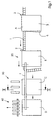
- the transport device according to the present invention is made by a Drive device driven, which is controlled by a control device.
- the Drive device 24 is coupled to the transport device 23, which, for. B. the Belts 7, 8, 11 or 12 may include, and the control device 25 is connected to the Drive device 24 coupled, as shown in Fig. 6.
- Controller 25, which may include a microcomputer will Drive device 24, the z. B. from a via an axis to the transport device 23rd coupled motor exists, activates and sets the belts of the transport device 23 in Move. As soon as the tapes have reached the book speed, this includes Pair of bands around a book and move the book away from the saddle chain.
- the control device 25 can additionally on (not Shown) sensors coupled to the position of the book on both the constant speed moving saddle chain as well as on the transport device can capture. These sensors are usually along the path of the books arranged.
- devices can also be provided that match the current Determine the status of the processing station and report it to the control device 25.
- a corresponding signal can be sent to the after the stapling process Control device 25 are transmitted. Based on these signals, the Control device 25 a signal to the drive device 24, the Drive device 24 for slowing down or accelerating and optionally for Causes opening or closing of the conveyor belts.
- Fig. 7a shows a schematic representation of a passive opening device, in which a side 5 a book in a fixed space between an outer volume 7 and an inner band 8 moves.
- the path of the outer band 7 is from the cooperating, fixed rollers 16, 14 and 16a, 14a determined, and the Gap between band 7 and band 8 is determined by the vertical distance between the Rollers 16a and 18a and 16 and 18 determined. This gap becomes narrow enough held to grasp one side of the signatures between the bands.
- there is no active physical opening and closing of the tapes when the page 5 of the book in the predetermined space between the tapes 7, 8 emotional.
- the page 5 of the bundle of signatures accordingly narrows Gap between bands 7, 8, and the book is then removed from the saddle chain moves when its front edge is gripped by the bands 7, 8.
- the Rollers 14, 16, 14a, 16a, 18 and 18a are rigidly arranged and determine the path of the Bands 7 and 8.
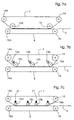
- Fig. 7b the belt 8 moves around two locally fixed rollers 18, 18a, the web of the Belt 8 is determined by the position of these immovable rollers.
- the rollers 14, 14a are fixed in position, while the rollers 15a-15c are movable in the direction of the arrow.
- All Movable rollers 15a-15c can e.g. B. each around an associated axis 13a-13c be pivotally arranged.
- the hinges are opened and closed by a Rotational movement of the movable rollers 15a-15c about their respective axes 13a to 13c the space between the bands 8 and 7 is increased or decreased.
- the outer band 7 along its entire length Open length.
- the movable rollers 15a-15c are simultaneously removed from the belt 8 moved away, the space between the bands 7, 8 increases along the entire length of band 7.
- the Path of the inner belt 8 from the position of the two fixed rollers 18, 18a determined while the path of the outer band 7 of the two fixed Rollers 14, 14a and a plurality of movably arranged rollers 15a-15d determined which in this case can be moved in the vertical direction by means of controllable springs 21 are.
- Each of the movable rollers 15a-15d can be controlled independently of the others are so that the movable rollers 15a-15d adjusted by a different amount can be.
- the are movable Rollers 15a and 15d are adjusted with respect to rolls 15c and 15b so that at the beginning and A space is created at the end of the tapes. Accordingly, page 5 of a book, that moves into the space between the bands 7, 8, easily between the Bands are gripped by the adjustable roller 15a in the direction of the inner one Band 8 is moved and so closes the gap when both bands open Signature speed have been brought.
- rollers 14, 14a and 18, 18a in FIG. 7 are described as being arranged in a stationary manner, these rollers can also be spatially variable, i.e. H. be designed to be movable.
- the Number of movable rollers 15 include any number, which means that the Number of movable rollers 15 is not limited to three or four as shown in is described by way of example in FIGS. 7b and 7c.
Landscapes
- Engineering & Computer Science (AREA)
- Mechanical Engineering (AREA)
- Textile Engineering (AREA)
- Delivering By Means Of Belts And Rollers (AREA)
- Feeding Of Articles By Means Other Than Belts Or Rollers (AREA)
- Separation, Sorting, Adjustment, Or Bending Of Sheets To Be Conveyed (AREA)
- Discharge By Other Means (AREA)
Applications Claiming Priority (2)
| Application Number | Priority Date | Filing Date | Title |
|---|---|---|---|
| GB9814952 | 1998-07-09 | ||
| GB9814952A GB2339192A (en) | 1998-07-09 | 1998-07-09 | Sheet transport |
Publications (3)
| Publication Number | Publication Date |
|---|---|
| EP0970820A2 true EP0970820A2 (fr) | 2000-01-12 |
| EP0970820A3 EP0970820A3 (fr) | 2000-08-23 |
| EP0970820B1 EP0970820B1 (fr) | 2003-08-20 |
Family
ID=10835277
Family Applications (1)
| Application Number | Title | Priority Date | Filing Date |
|---|---|---|---|
| EP99111954A Expired - Lifetime EP0970820B1 (fr) | 1998-07-09 | 1999-06-24 | Dispositif de transport |
Country Status (4)
| Country | Link |
|---|---|
| US (1) | US6270068B1 (fr) |
| EP (1) | EP0970820B1 (fr) |
| DE (1) | DE59906643D1 (fr) |
| GB (1) | GB2339192A (fr) |
Cited By (3)
| Publication number | Priority date | Publication date | Assignee | Title |
|---|---|---|---|---|
| EP1574355A2 (fr) * | 2004-03-10 | 2005-09-14 | Hohner Maschinenbau GmbH | Encarteuse-piqueuse avec une station de piqûre |
| WO2011042756A3 (fr) * | 2009-10-08 | 2011-10-06 | Ibis Integrated Bindery Systems Limited | Appareil de reliure de livres |
| EP3216619A1 (fr) * | 2016-03-07 | 2017-09-13 | Müller Martini Holding AG | Dispositif et procédé de transport de blocs de livre |
Families Citing this family (7)
| Publication number | Priority date | Publication date | Assignee | Title |
|---|---|---|---|---|
| DE10130662A1 (de) * | 2001-06-28 | 2003-01-16 | Heidelberger Druckmasch Ag | Sammelhefter mit einem Führungselement im Heftbereich |
| US7033123B2 (en) * | 2002-02-28 | 2006-04-25 | Hewlett-Packard Development Company, L.P. | Booklet maker |
| US6981830B2 (en) * | 2002-02-28 | 2006-01-03 | Hewlett-Packard Development Company, L.P. | Pivotable collecting device |
| DE50206687D1 (de) * | 2002-11-29 | 2006-06-08 | Mueller Martini Holding Ag | Einrichtung zur Herstellung eines gebundenen Druckerzeugnisses |
| DE502004011656D1 (de) * | 2004-02-03 | 2010-10-28 | Mueller Martini Holding Ag | Einrichtung zur Herstellung von aus gefalzten Druckbogen bestehenden fadengehefteten Buchblocks |
| ATE544708T1 (de) * | 2009-08-13 | 2012-02-15 | Mueller Martini Holding Ag | Vorrichtung und verfahren zum übergeben von druckbogen |
| EP2492107B1 (fr) * | 2011-02-25 | 2013-07-24 | Müller Martini Holding AG | Couseuse au fil textile |
Citations (1)
| Publication number | Priority date | Publication date | Assignee | Title |
|---|---|---|---|---|
| US3317026A (en) | 1964-09-29 | 1967-05-02 | Harris Intertype Corp | Signature handling mechanism |
Family Cites Families (16)
| Publication number | Priority date | Publication date | Assignee | Title |
|---|---|---|---|---|
| US2028231A (en) * | 1936-01-21 | belt conveyer | ||
| US1618591A (en) * | 1925-06-30 | 1927-02-22 | James A Jacobsen | Feeding mechanism for stitching machines |
| US1985850A (en) * | 1931-08-12 | 1934-12-25 | Western Union Telegraph Co | Drag conveyer |
| US2006294A (en) * | 1932-01-21 | 1935-06-25 | Western Union Telegraph Co | Drag conveyer channel |
| US1973041A (en) * | 1932-08-27 | 1934-09-11 | Western Union Telegraph Co | Drag conveyer and belt |
| US2028236A (en) * | 1933-09-02 | 1936-01-21 | John T Needham | Belt conveyer |
| US3239214A (en) * | 1963-08-21 | 1966-03-08 | Rauschenberger Willia Franklin | Signature feeder to stacker |
| CH627422A5 (de) * | 1977-12-22 | 1982-01-15 | Harris Corp | Einrichtung fuer die behandlung von schriftstuecken, die zwischen behandlungsstationen befoerdert werden. |
| US4262897A (en) * | 1979-10-01 | 1981-04-21 | Kimberly-Clark Corporation | Vertical-to-horizontal conveyor system |
| US4493482A (en) * | 1983-09-27 | 1985-01-15 | Alden Press, Inc. | Motion stabilizing and aligning apparatus for moving folded signatures through an ink jet printer |
| US4522384A (en) * | 1983-09-30 | 1985-06-11 | World Color Press, Inc. | Machine for collating signatures in the saddle format |
| US4519599A (en) * | 1984-05-11 | 1985-05-28 | R. R. Donnelley & Sons Company | Method and apparatus for tandem stitching of books in a bindery line |
| US4747817A (en) * | 1986-07-03 | 1988-05-31 | Newsome John R | High speed signature manipulating apparatus |
| US5028193A (en) * | 1989-04-26 | 1991-07-02 | Misicka James A | Saddle-bound books, magazines and the like and process for manufacture same |
| US5158273A (en) * | 1991-04-05 | 1992-10-27 | Wagner & Teldon Publishing Ltd. | Method and apparatus for die-cutting signatures in saddle format |
| EP0893275B1 (fr) * | 1997-07-25 | 2001-07-04 | Grapha-Holding Ag | Méthode pour la fabrication de livres ou de cahiers |
-
1998
- 1998-07-09 GB GB9814952A patent/GB2339192A/en not_active Withdrawn
-
1999
- 1999-06-24 DE DE59906643T patent/DE59906643D1/de not_active Expired - Fee Related
- 1999-06-24 EP EP99111954A patent/EP0970820B1/fr not_active Expired - Lifetime
- 1999-07-07 US US09/348,968 patent/US6270068B1/en not_active Expired - Fee Related
Patent Citations (1)
| Publication number | Priority date | Publication date | Assignee | Title |
|---|---|---|---|---|
| US3317026A (en) | 1964-09-29 | 1967-05-02 | Harris Intertype Corp | Signature handling mechanism |
Cited By (4)
| Publication number | Priority date | Publication date | Assignee | Title |
|---|---|---|---|---|
| EP1574355A2 (fr) * | 2004-03-10 | 2005-09-14 | Hohner Maschinenbau GmbH | Encarteuse-piqueuse avec une station de piqûre |
| EP1574355A3 (fr) * | 2004-03-10 | 2011-01-05 | Hohner Maschinenbau GmbH | Encarteuse-piqueuse avec une station de piqûre |
| WO2011042756A3 (fr) * | 2009-10-08 | 2011-10-06 | Ibis Integrated Bindery Systems Limited | Appareil de reliure de livres |
| EP3216619A1 (fr) * | 2016-03-07 | 2017-09-13 | Müller Martini Holding AG | Dispositif et procédé de transport de blocs de livre |
Also Published As
| Publication number | Publication date |
|---|---|
| GB2339192A (en) | 2000-01-19 |
| GB9814952D0 (en) | 1998-09-09 |
| US6270068B1 (en) | 2001-08-07 |
| EP0970820B1 (fr) | 2003-08-20 |
| EP0970820A3 (fr) | 2000-08-23 |
| DE59906643D1 (de) | 2003-09-25 |
Similar Documents
| Publication | Publication Date | Title |
|---|---|---|
| EP0911291B1 (fr) | Dispositif de pliage dans une machine plieuse à grande vitesse | |
| CH667621A5 (de) | Sammelhefter. | |
| DE3221001A1 (de) | Foerdervorrichtungen fuer zeitungen und dergleichen | |
| EP0970820B1 (fr) | Dispositif de transport | |
| EP0342490B1 (fr) | Machine à plier | |
| CH691058A5 (de) | Vorrichtung zum Verarbeiten gefalzter Druckbogen. | |
| EP0854105B1 (fr) | Méthode et dispositif pour traiter des produits imprimes plats, comme des journaux, des magazines, et des parties de cela | |
| EP0897890B1 (fr) | Procédé et dispositif pour produire un courant de produits tournés avec une pince de préhension de coin | |
| EP0518181B1 (fr) | Unité de préhension réglable dans des machines d'impression | |
| DE102012207295B4 (de) | Verfahren und Vorrichtung zur Herstellung von Büchern mit Drahtkamm- oder Spiralbindung oder anderen vergleichbaren Bindungen | |
| EP1528023B1 (fr) | Méthode et dispositif pour changer un flux d'articles plats | |
| DE602004009749T2 (de) | Vorrichtung zum Stapeln von Signaturen | |
| EP0976672B1 (fr) | Dispositif de transport | |
| EP0250758A1 (fr) | Dispositif de pliage et de convoyage | |
| EP0551055A2 (fr) | Procédé et dispositif pour assembler des imprimés | |
| EP0169489B1 (fr) | Dispositif pour plier et transformer des imprimés | |
| DE1436064C3 (de) | Vorrichtung zum Zusammentragen gefalzter Bogen zu einem Buchblock | |
| DE1561141A1 (de) | Vorrichtung zum OEffnen eines mehrblaettrigen Papiererzeugnisses an einer durch Reibungsminderung vorbestimmten Stelle und zum Einfuehren einer Beilage in das geoeffnete Erzeugnis | |
| DE1153383B (de) | Einrichtung zum Ablegen der bogenfoermigen Produkte einer Rotationsdruckmaschine | |
| EP0170179A1 (fr) | Dispositif pour recueillir des produits pliés à partir d'un cylindre à volets de pliage | |
| DE19828625A1 (de) | Maschine und Verfahren zum kontinuierlichen Falzen von Papierbogen, insbesondere für die Herstellung von gefalzten Signaturen | |
| EP1110894B1 (fr) | Méthode et dispositif pour plier des feuilles de matériau | |
| DE3100866A1 (de) | Maschine zum transportieren einer folge von buechern | |
| DE10111648A1 (de) | Vorrichtung zum Schneiden und Falzen von Signaturen | |
| DE3738139A1 (de) | Verfahren und vorrichtung zum zick-zack-falten und stapelbilden von materialbahnen |
Legal Events
| Date | Code | Title | Description |
|---|---|---|---|
| PUAI | Public reference made under article 153(3) epc to a published international application that has entered the european phase |
Free format text: ORIGINAL CODE: 0009012 |
|
| AK | Designated contracting states |
Kind code of ref document: A2 Designated state(s): BE CH DE FR GB IT LI NL |
|
| AX | Request for extension of the european patent |
Free format text: AL;LT;LV;MK;RO;SI |
|
| PUAL | Search report despatched |
Free format text: ORIGINAL CODE: 0009013 |
|
| AK | Designated contracting states |
Kind code of ref document: A3 Designated state(s): AT BE CH CY DE DK ES FI FR GB GR IE IT LI LU MC NL PT SE |
|
| AX | Request for extension of the european patent |
Free format text: AL;LT;LV;MK;RO;SI |
|
| 17P | Request for examination filed |
Effective date: 20000822 |
|
| AKX | Designation fees paid |
Free format text: BE CH DE FR GB IT LI NL |
|
| GRAH | Despatch of communication of intention to grant a patent |
Free format text: ORIGINAL CODE: EPIDOS IGRA |
|
| GRAH | Despatch of communication of intention to grant a patent |
Free format text: ORIGINAL CODE: EPIDOS IGRA |
|
| GRAA | (expected) grant |
Free format text: ORIGINAL CODE: 0009210 |
|
| AK | Designated contracting states |
Designated state(s): BE CH DE FR GB IT LI NL |
|
| REG | Reference to a national code |
Ref country code: GB Ref legal event code: FG4D Free format text: NOT ENGLISH |
|
| REG | Reference to a national code |
Ref country code: CH Ref legal event code: EP |
|
| REF | Corresponds to: |
Ref document number: 59906643 Country of ref document: DE Date of ref document: 20030925 Kind code of ref document: P |
|
| GBT | Gb: translation of ep patent filed (gb section 77(6)(a)/1977) |
Effective date: 20031029 |
|
| ET | Fr: translation filed | ||
| PGFP | Annual fee paid to national office [announced via postgrant information from national office to epo] |
Ref country code: FR Payment date: 20040618 Year of fee payment: 6 |
|
| PGFP | Annual fee paid to national office [announced via postgrant information from national office to epo] |
Ref country code: NL Payment date: 20040622 Year of fee payment: 6 |
|
| PLBE | No opposition filed within time limit |
Free format text: ORIGINAL CODE: 0009261 |
|
| STAA | Information on the status of an ep patent application or granted ep patent |
Free format text: STATUS: NO OPPOSITION FILED WITHIN TIME LIMIT |
|
| PGFP | Annual fee paid to national office [announced via postgrant information from national office to epo] |
Ref country code: BE Payment date: 20040628 Year of fee payment: 6 |
|
| 26N | No opposition filed |
Effective date: 20040524 |
|
| PG25 | Lapsed in a contracting state [announced via postgrant information from national office to epo] |
Ref country code: IT Free format text: LAPSE BECAUSE OF NON-PAYMENT OF DUE FEES Effective date: 20050624 |
|
| PG25 | Lapsed in a contracting state [announced via postgrant information from national office to epo] |
Ref country code: BE Free format text: LAPSE BECAUSE OF NON-PAYMENT OF DUE FEES Effective date: 20050630 |
|
| PG25 | Lapsed in a contracting state [announced via postgrant information from national office to epo] |
Ref country code: NL Free format text: LAPSE BECAUSE OF NON-PAYMENT OF DUE FEES Effective date: 20060101 |
|
| PG25 | Lapsed in a contracting state [announced via postgrant information from national office to epo] |
Ref country code: FR Free format text: LAPSE BECAUSE OF NON-PAYMENT OF DUE FEES Effective date: 20060228 |
|
| NLV4 | Nl: lapsed or anulled due to non-payment of the annual fee |
Effective date: 20060101 |
|
| REG | Reference to a national code |
Ref country code: FR Ref legal event code: ST Effective date: 20060228 |
|
| PGFP | Annual fee paid to national office [announced via postgrant information from national office to epo] |
Ref country code: CH Payment date: 20060613 Year of fee payment: 8 |
|
| BERE | Be: lapsed |
Owner name: *HEIDELBERGER DRUCKMASCHINEN A.G. Effective date: 20050630 |
|
| REG | Reference to a national code |
Ref country code: CH Ref legal event code: PL |
|
| PG25 | Lapsed in a contracting state [announced via postgrant information from national office to epo] |
Ref country code: LI Free format text: LAPSE BECAUSE OF NON-PAYMENT OF DUE FEES Effective date: 20070630 Ref country code: CH Free format text: LAPSE BECAUSE OF NON-PAYMENT OF DUE FEES Effective date: 20070630 |
|
| PGFP | Annual fee paid to national office [announced via postgrant information from national office to epo] |
Ref country code: DE Payment date: 20080630 Year of fee payment: 10 |
|
| PGFP | Annual fee paid to national office [announced via postgrant information from national office to epo] |
Ref country code: GB Payment date: 20080630 Year of fee payment: 10 |
|
| GBPC | Gb: european patent ceased through non-payment of renewal fee |
Effective date: 20090624 |
|
| PG25 | Lapsed in a contracting state [announced via postgrant information from national office to epo] |
Ref country code: GB Free format text: LAPSE BECAUSE OF NON-PAYMENT OF DUE FEES Effective date: 20090624 |
|
| PG25 | Lapsed in a contracting state [announced via postgrant information from national office to epo] |
Ref country code: DE Free format text: LAPSE BECAUSE OF NON-PAYMENT OF DUE FEES Effective date: 20100101 |