EP1588955A1 - Lager- und Transportbehälter - Google Patents
Lager- und Transportbehälter Download PDFInfo
- Publication number
- EP1588955A1 EP1588955A1 EP05005199A EP05005199A EP1588955A1 EP 1588955 A1 EP1588955 A1 EP 1588955A1 EP 05005199 A EP05005199 A EP 05005199A EP 05005199 A EP05005199 A EP 05005199A EP 1588955 A1 EP1588955 A1 EP 1588955A1
- Authority
- EP
- European Patent Office
- Prior art keywords
- lid
- container
- halves
- storage
- handle
- Prior art date
- Legal status (The legal status is an assumption and is not a legal conclusion. Google has not performed a legal analysis and makes no representation as to the accuracy of the status listed.)
- Granted
Links
Images


Classifications
-
- E—FIXED CONSTRUCTIONS
- E05—LOCKS; KEYS; WINDOW OR DOOR FITTINGS; SAFES
- E05C—BOLTS OR FASTENING DEVICES FOR WINGS, SPECIALLY FOR DOORS OR WINDOWS
- E05C19/00—Other devices specially designed for securing wings, e.g. with suction cups
- E05C19/06—Other devices specially designed for securing wings, e.g. with suction cups in which the securing part if formed or carried by a spring and moves only by distortion of the spring, e.g. snaps
-
- B—PERFORMING OPERATIONS; TRANSPORTING
- B65—CONVEYING; PACKING; STORING; HANDLING THIN OR FILAMENTARY MATERIAL
- B65D—CONTAINERS FOR STORAGE OR TRANSPORT OF ARTICLES OR MATERIALS, e.g. BAGS, BARRELS, BOTTLES, BOXES, CANS, CARTONS, CRATES, DRUMS, JARS, TANKS, HOPPERS, FORWARDING CONTAINERS; ACCESSORIES, CLOSURES, OR FITTINGS THEREFOR; PACKAGING ELEMENTS; PACKAGES
- B65D43/00—Lids or covers for rigid or semi-rigid containers
- B65D43/14—Non-removable lids or covers
- B65D43/16—Non-removable lids or covers hinged for upward or downward movement
- B65D43/163—Non-removable lids or covers hinged for upward or downward movement the container and the lid being made separately
- B65D43/164—Non-removable lids or covers hinged for upward or downward movement the container and the lid being made separately and connected by interfitting hinge elements integrally with the container and the lid formed respectively
-
- E—FIXED CONSTRUCTIONS
- E05—LOCKS; KEYS; WINDOW OR DOOR FITTINGS; SAFES
- E05B—LOCKS; ACCESSORIES THEREFOR; HANDCUFFS
- E05B65/00—Locks or fastenings for special use
- E05B65/52—Other locks for chests, boxes, trunks, baskets, travelling bags, or the like
-
- B—PERFORMING OPERATIONS; TRANSPORTING
- B65—CONVEYING; PACKING; STORING; HANDLING THIN OR FILAMENTARY MATERIAL
- B65D—CONTAINERS FOR STORAGE OR TRANSPORT OF ARTICLES OR MATERIALS, e.g. BAGS, BARRELS, BOTTLES, BOXES, CANS, CARTONS, CRATES, DRUMS, JARS, TANKS, HOPPERS, FORWARDING CONTAINERS; ACCESSORIES, CLOSURES, OR FITTINGS THEREFOR; PACKAGING ELEMENTS; PACKAGES
- B65D2251/00—Details relating to container closures
- B65D2251/10—Details of hinged closures
- B65D2251/1083—Closures formed of several sections hinged to the container or base
-
- Y—GENERAL TAGGING OF NEW TECHNOLOGICAL DEVELOPMENTS; GENERAL TAGGING OF CROSS-SECTIONAL TECHNOLOGIES SPANNING OVER SEVERAL SECTIONS OF THE IPC; TECHNICAL SUBJECTS COVERED BY FORMER USPC CROSS-REFERENCE ART COLLECTIONS [XRACs] AND DIGESTS
- Y02—TECHNOLOGIES OR APPLICATIONS FOR MITIGATION OR ADAPTATION AGAINST CLIMATE CHANGE
- Y02W—CLIMATE CHANGE MITIGATION TECHNOLOGIES RELATED TO WASTEWATER TREATMENT OR WASTE MANAGEMENT
- Y02W30/00—Technologies for solid waste management
- Y02W30/50—Reuse, recycling or recovery technologies
- Y02W30/80—Packaging reuse or recycling, e.g. of multilayer packaging
Definitions
- the invention relates to a storage and transport container comprising one two hinged, swung outward, in the open position with the Container wall latchable lid halves existing lid, with the lid halves are provided with at least one sliding latch, the has a handle above the lid half.
- a container or box with a lid, which by a locking latch the Container opening is lockable with the container body lockable is through EP 0 104 136 B1 has become known.
- Both as usual by injection molding made of plastic one-piece container and the lid have circumferential, on each congruent resting container flanges.
- Two opposite Longitudinal edges of the flanges of lid and container are each with two provided parallel to the lid or container edge extending slots in the closed position in pairs aligned.
- Each locking bar has a tapering downwards Plug-in part, which is connected via a neck with the handle part, wherein the neck guided in the slot of the cover flange on sliding plates or rails.
- the invention is based on the object, a storage and transport container or box of the aforementioned type to provide a fixation of the open Cover halves in a simple manner and with less effort ..
- a preferred embodiment of the invention provides that the VerInstitutriegeln In the container wall associated latching receptacles formed with an undercut are.
- the pivoted-lid halves need only to the container longitudinal wall to be pressed, with the locking latch on immersion automatically move up or relocate in the snap shots and successively engage in the introduced undercut and lock it through what is easy contact or back pressure of the lid half can be achieved easily.
- To the Swiveling the cover halves in the closed position allows the locking of the Lift handles of the locking latch in the locking receptacles just as easily, because the contouring of the locking receptacles on the handle parts, the displacement of the Make locking latch, so that the handle parts by an upward Movement gradually from the undercuts solve and in the episode completely come free.
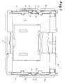
- rectangular storage and transport container 1 consists of a bottom 2, end walls 3 and longitudinal walls 4 and one of two cover halves 5a, 5b existing lid.
- the cover halves 5a, 5b are hinged hinged at the upper edge of the container and in its swung open, shown with the container longitudinal walls 4 latched position.
- the lids occupy their tilted closing position covering the container opening, this is provided by on the cover halves 5a, 5b provided Sch thoroughlyriegeln 6 secured, one of which in each case on an end wall side of the container 1 in the cover halves 5a and 5b is provided.
- the locking latches 6, comprising a sliding sliding plate element, have at their in the installed position in the cover halves 5a and 5b upper side with a finger of a hand-to-handle part 7 and on their undersides a hooking projection 8 (see Fig. 2 and the left half of Fig. 1) on.
- the Einhakvorsprünge 8 of the locking latch 7 engage in openings of the container upper edge one.
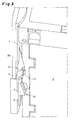
- the locking latches 6 serve in FIG the pivoted-up position of the cover halves 5a and 5b simultaneously to the narrow adjacent latching with the container longitudinal walls 4.
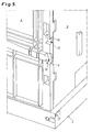
- the longitudinal walls 4 are for this purpose in their side areas to the handle parts 7 of the locking bolt 6 as far as possible contour parallel and also formed with an undercut 9 Catches 10 provided (see Figures 4 and 5).
- the locking receptacles 10 are formed rising from its undercut 9 to the front or outside rising.
- the cover halves 5a and 5b are in the embodiment except with the locking bolts 6 also with ergonomically shaped, in Fig. 6 as a detail shown handles 11 for gripping and pivoting the cover halves 5a, 5b provided in their respective position of use.
- the handles 11 can be for additional catch safety of the pivoted-lid halves 5a and 5b in use the container longitudinal walls 4.
- the handles 11 also Lock receptacles 12 assigned, at its upper, the upper edge of the container 1 facing end have a nose-like projection 13 (see 4 and 5), the contour parallel to a slightly rounded head plate 14 (see FIG. 6) of the handle 11 and the top plate 14 engages over something in the locking position.
- the pivoted-lid halves 5a and 5b with or on the container longitudinal walls 4 serve in any case only on the cover halves anyway existing components.
- the displaceable arrangement of the Lock bolt also used for automatic locking and unlocking, what else by the matched shape of the interlocking locking elements is favored and supported. A close, safe installation of the lid halves at the container longitudinal walls is guaranteed.
Landscapes
- Engineering & Computer Science (AREA)
- Mechanical Engineering (AREA)
- Closures For Containers (AREA)
Abstract
Description
- Fig. 1
- einen Lager- und Transportbehälter von einer Stirnwand her gesehen mit aufgeklappten bzw. weggeschwenkten und in den Behälterlängswänden verrasteten Deckelhälften;
- Fig. 2
- als Einzelheit des Behälters nach Fig. 1 die Verrastung der linken Deckelhälfte in der angrenzenden Behälterlängswand;
- Fig. 3
- die Einzelheit der Fig. 2 in einer perspektivischen Darstellung;
- Fig. 4
- als Einzelheit in einer perspektivischen Vorderansicht die in die Behälterlängswand eingearbeiteten Rastaufnahmen;
- Fig. 5
- die Einzelheit der Fig. 4 aus einer etwas anderen Perspektive; und
- Fig. 6
- als Einzelheit in einer perspektivischen Darstellung einen an den Deckelhälften ausgebildeten, ergonomischen Handgriff.
Claims (5)
- Lager- und Transportbehälter, umfassend einen aus zwei anscharnierten, nach außen wegschwenkbaren, in der Öffnungslage mit der Behälterwand verrastbaren Deckelhälften bestehenden Deckel, wobei die Deckelhälften mit mindestens einem verschiebbaren Verschlussriegel versehen sind, der oberhalb der Deckelhälfte ein Griffteil aufweist,
dadurch gekennzeichnet, daß die offen geschwenkten Deckelhälften (5a, 5b) unmittelbar mit dem Griffteil (7) ihrer Verschlussriegel (6) in die jeweilige Behälterwand (4) einrasten. - Lager- und Transportbehälter nach Anspruch 1,
dadurch gekennzeichnet, daß den Griffteilen (7) der Verschlußriegel (6) in der Behälterwand (4) zugeordnete Rastaufnahmen (10) mit einem Hinterschnitt (9) ausgebildet sind. - Lager- und Transportbehälter nach Anspruch 1 oder 2,
dadurch gekennzeichnet, daß an den Deckelhälften (5a, 5b) angeordnete Handgriffe (11) in die jeweilige Behälterwand (4) einrasten. - Lager- und Transportbehälter nach Anspruch 3,
dadurch gekennzeichnet, daß den Handgriffen (11) in der Behälterwand (4) zugeordnete Rastaufnahmen (12) als nasenartige, das vordere Handgriffende übergreifende Vorsprünge (13) ausgebildet sind. - Lager- und Transportbehälter nach einem der Ansprüche 1 bis 4,
dadurch gekennzeichnet, daß die Rastaufnahmen (10; 12) zumindest bereichsweise konturparallel zu dem Griffteil (7) des Verschlussriegels (6) bzw. dem Handgriff (11) ausgebildet sind.
Applications Claiming Priority (4)
| Application Number | Priority Date | Filing Date | Title |
|---|---|---|---|
| DE202004006398 | 2004-04-20 | ||
| DE202004006398U | 2004-04-20 | ||
| DE202005000845U | 2005-01-18 | ||
| DE200520000845 DE202005000845U1 (de) | 2004-04-20 | 2005-01-18 | Lager- und Transportbehälter |
Publications (2)
| Publication Number | Publication Date |
|---|---|
| EP1588955A1 true EP1588955A1 (de) | 2005-10-26 |
| EP1588955B1 EP1588955B1 (de) | 2008-09-17 |
Family
ID=34934167
Family Applications (1)
| Application Number | Title | Priority Date | Filing Date |
|---|---|---|---|
| EP20050005199 Expired - Lifetime EP1588955B1 (de) | 2004-04-20 | 2005-03-10 | Lager- und Transportbehälter |
Country Status (2)
| Country | Link |
|---|---|
| US (1) | US7448513B2 (de) |
| EP (1) | EP1588955B1 (de) |
Families Citing this family (4)
| Publication number | Priority date | Publication date | Assignee | Title |
|---|---|---|---|---|
| DE202004017452U1 (de) * | 2004-11-11 | 2005-02-17 | Fritz Schäfer GmbH | Zusammenfaltbarer Lager- und Transportbehälter bzw. -kasten |
| US7967162B2 (en) * | 2007-04-18 | 2011-06-28 | John D. Brush & Co., Inc. | Double-walled blow-molded container including an undercut feature |
| US20090173744A1 (en) * | 2008-01-03 | 2009-07-09 | Hassell Jon P | Container with lid |
| US20240286802A1 (en) * | 2020-10-22 | 2024-08-29 | Garin Toren | Kitchen container |
Citations (3)
| Publication number | Priority date | Publication date | Assignee | Title |
|---|---|---|---|---|
| US3850464A (en) * | 1973-05-23 | 1974-11-26 | R Bisbing | Slam-latch |
| EP0104136A2 (de) * | 1982-09-22 | 1984-03-28 | Georg Utz AG | Behälter mit Deckel und Verschlussriegel |
| US6179156B1 (en) * | 2000-02-04 | 2001-01-30 | Rehrig Pacific Company | Multi-purpose container |
Family Cites Families (4)
| Publication number | Priority date | Publication date | Assignee | Title |
|---|---|---|---|---|
| US4161261A (en) * | 1978-05-05 | 1979-07-17 | Menasha Corporation | Security container |
| US5501503A (en) * | 1994-03-24 | 1996-03-26 | Thayer; Henry | Vehicular door |
| EP1428764B1 (de) | 2002-12-13 | 2006-06-28 | Georg Utz Holding AG | Stapelbehälter |
| USD493282S1 (en) * | 2003-05-14 | 2004-07-27 | Georg Utz Holding, Ag | Plastic storage box |
-
2005
- 2005-03-10 EP EP20050005199 patent/EP1588955B1/de not_active Expired - Lifetime
- 2005-04-12 US US11/108,035 patent/US7448513B2/en active Active
Patent Citations (3)
| Publication number | Priority date | Publication date | Assignee | Title |
|---|---|---|---|---|
| US3850464A (en) * | 1973-05-23 | 1974-11-26 | R Bisbing | Slam-latch |
| EP0104136A2 (de) * | 1982-09-22 | 1984-03-28 | Georg Utz AG | Behälter mit Deckel und Verschlussriegel |
| US6179156B1 (en) * | 2000-02-04 | 2001-01-30 | Rehrig Pacific Company | Multi-purpose container |
Also Published As
| Publication number | Publication date |
|---|---|
| US7448513B2 (en) | 2008-11-11 |
| US20050233621A1 (en) | 2005-10-20 |
| EP1588955B1 (de) | 2008-09-17 |
Similar Documents
| Publication | Publication Date | Title |
|---|---|---|
| EP2189381B1 (de) | Tragbarer Transport- oder Lagerbehälter | |
| EP1305145B1 (de) | Werkzeugkoffer | |
| EP1516703B1 (de) | Stapelbarer Werkzeugkoffer | |
| EP2994274B1 (de) | Behälteranordnung | |
| DE202005017057U1 (de) | Behälter für Lebensmittel | |
| EP1533244B1 (de) | Behälter mit schwenkbar angelenktem Deckel | |
| EP1688076A1 (de) | Gargefäss | |
| EP2226265B1 (de) | Behälter mit Deckel und Verschlussriegel | |
| EP1588955B1 (de) | Lager- und Transportbehälter | |
| EP4479315B1 (de) | Aufbewahrungseinrichtung | |
| DE112006002236T5 (de) | Behälter mit offenem Ende und Verschlussdeckel | |
| AT400702B (de) | Kasten aus kunststoff | |
| EP3997004B1 (de) | Behaelter mit verriegelbarem deckel | |
| DE202005000845U1 (de) | Lager- und Transportbehälter | |
| DE3301649C2 (de) | ||
| DE29922447U1 (de) | Abdichtbarer Behälter | |
| EP3817894B1 (de) | Aufbewahrungseinrichtung | |
| CH695684A5 (de) | Behälter für Lebensmittel. | |
| DE20314261U1 (de) | Behälter, insbesondere aus Kunststoff | |
| DE102008037009A1 (de) | Werkzeugbox | |
| DE69504786T2 (de) | Behälter | |
| DE102023128317B3 (de) | Transportbehälter und Behälteranordnung | |
| DE9205914U1 (de) | Koffer | |
| DE202007006158U1 (de) | Verriegelung für Betonschränke und Containerboxen | |
| DE3002408A1 (de) | Vorrichtung zur sicherung von schubladen in schubladenschraenken |
Legal Events
| Date | Code | Title | Description |
|---|---|---|---|
| PUAI | Public reference made under article 153(3) epc to a published international application that has entered the european phase |
Free format text: ORIGINAL CODE: 0009012 |
|
| AK | Designated contracting states |
Kind code of ref document: A1 Designated state(s): AT BE BG CH CY CZ DE DK EE ES FI FR GB GR HU IE IS IT LI LT LU MC NL PL PT RO SE SI SK TR |
|
| AX | Request for extension of the european patent |
Extension state: AL BA HR LV MK YU |
|
| 17P | Request for examination filed |
Effective date: 20060420 |
|
| AKX | Designation fees paid |
Designated state(s): AT BE BG CH CY CZ DE DK EE ES FI FR GB GR HU IE IS IT LI LT LU MC NL PL PT RO SE SI SK TR |
|
| GRAP | Despatch of communication of intention to grant a patent |
Free format text: ORIGINAL CODE: EPIDOSNIGR1 |
|
| GRAS | Grant fee paid |
Free format text: ORIGINAL CODE: EPIDOSNIGR3 |
|
| GRAA | (expected) grant |
Free format text: ORIGINAL CODE: 0009210 |
|
| AK | Designated contracting states |
Kind code of ref document: B1 Designated state(s): AT BE BG CH CY CZ DE DK EE ES FI FR GB GR HU IE IS IT LI LT LU MC NL PL PT RO SE SI SK TR |
|
| REG | Reference to a national code |
Ref country code: GB Ref legal event code: FG4D Free format text: NOT ENGLISH |
|
| REG | Reference to a national code |
Ref country code: CH Ref legal event code: EP |
|
| REG | Reference to a national code |
Ref country code: IE Ref legal event code: FG4D Free format text: LANGUAGE OF EP DOCUMENT: GERMAN |
|
| REF | Corresponds to: |
Ref document number: 502005005372 Country of ref document: DE Date of ref document: 20081030 Kind code of ref document: P |
|
| REG | Reference to a national code |
Ref country code: CH Ref legal event code: NV Representative=s name: SCHMAUDER & PARTNER AG PATENTANWALTSBUERO |
|
| PG25 | Lapsed in a contracting state [announced via postgrant information from national office to epo] |
Ref country code: LT Free format text: LAPSE BECAUSE OF FAILURE TO SUBMIT A TRANSLATION OF THE DESCRIPTION OR TO PAY THE FEE WITHIN THE PRESCRIBED TIME-LIMIT Effective date: 20080917 |
|
| PG25 | Lapsed in a contracting state [announced via postgrant information from national office to epo] |
Ref country code: SI Free format text: LAPSE BECAUSE OF FAILURE TO SUBMIT A TRANSLATION OF THE DESCRIPTION OR TO PAY THE FEE WITHIN THE PRESCRIBED TIME-LIMIT Effective date: 20080917 Ref country code: FI Free format text: LAPSE BECAUSE OF FAILURE TO SUBMIT A TRANSLATION OF THE DESCRIPTION OR TO PAY THE FEE WITHIN THE PRESCRIBED TIME-LIMIT Effective date: 20080917 |
|
| REG | Reference to a national code |
Ref country code: IE Ref legal event code: FD4D |
|
| PG25 | Lapsed in a contracting state [announced via postgrant information from national office to epo] |
Ref country code: BG Free format text: LAPSE BECAUSE OF FAILURE TO SUBMIT A TRANSLATION OF THE DESCRIPTION OR TO PAY THE FEE WITHIN THE PRESCRIBED TIME-LIMIT Effective date: 20081217 Ref country code: ES Free format text: LAPSE BECAUSE OF FAILURE TO SUBMIT A TRANSLATION OF THE DESCRIPTION OR TO PAY THE FEE WITHIN THE PRESCRIBED TIME-LIMIT Effective date: 20081228 |
|
| PG25 | Lapsed in a contracting state [announced via postgrant information from national office to epo] |
Ref country code: CZ Free format text: LAPSE BECAUSE OF FAILURE TO SUBMIT A TRANSLATION OF THE DESCRIPTION OR TO PAY THE FEE WITHIN THE PRESCRIBED TIME-LIMIT Effective date: 20080917 Ref country code: IS Free format text: LAPSE BECAUSE OF FAILURE TO SUBMIT A TRANSLATION OF THE DESCRIPTION OR TO PAY THE FEE WITHIN THE PRESCRIBED TIME-LIMIT Effective date: 20090117 Ref country code: PT Free format text: LAPSE BECAUSE OF FAILURE TO SUBMIT A TRANSLATION OF THE DESCRIPTION OR TO PAY THE FEE WITHIN THE PRESCRIBED TIME-LIMIT Effective date: 20090217 Ref country code: RO Free format text: LAPSE BECAUSE OF FAILURE TO SUBMIT A TRANSLATION OF THE DESCRIPTION OR TO PAY THE FEE WITHIN THE PRESCRIBED TIME-LIMIT Effective date: 20080917 Ref country code: SK Free format text: LAPSE BECAUSE OF FAILURE TO SUBMIT A TRANSLATION OF THE DESCRIPTION OR TO PAY THE FEE WITHIN THE PRESCRIBED TIME-LIMIT Effective date: 20080917 |
|
| PLBE | No opposition filed within time limit |
Free format text: ORIGINAL CODE: 0009261 |
|
| STAA | Information on the status of an ep patent application or granted ep patent |
Free format text: STATUS: NO OPPOSITION FILED WITHIN TIME LIMIT |
|
| PG25 | Lapsed in a contracting state [announced via postgrant information from national office to epo] |
Ref country code: IE Free format text: LAPSE BECAUSE OF FAILURE TO SUBMIT A TRANSLATION OF THE DESCRIPTION OR TO PAY THE FEE WITHIN THE PRESCRIBED TIME-LIMIT Effective date: 20080917 Ref country code: DK Free format text: LAPSE BECAUSE OF FAILURE TO SUBMIT A TRANSLATION OF THE DESCRIPTION OR TO PAY THE FEE WITHIN THE PRESCRIBED TIME-LIMIT Effective date: 20080917 Ref country code: EE Free format text: LAPSE BECAUSE OF FAILURE TO SUBMIT A TRANSLATION OF THE DESCRIPTION OR TO PAY THE FEE WITHIN THE PRESCRIBED TIME-LIMIT Effective date: 20080917 |
|
| REG | Reference to a national code |
Ref country code: CH Ref legal event code: PCAR Free format text: SCHMAUDER & PARTNER AG PATENT- UND MARKENANWAELTE VSP;ZWAENGIWEG 7;8038 ZUERICH (CH) |
|
| 26N | No opposition filed |
Effective date: 20090618 |
|
| PG25 | Lapsed in a contracting state [announced via postgrant information from national office to epo] |
Ref country code: IT Free format text: LAPSE BECAUSE OF FAILURE TO SUBMIT A TRANSLATION OF THE DESCRIPTION OR TO PAY THE FEE WITHIN THE PRESCRIBED TIME-LIMIT Effective date: 20080917 |
|
| PG25 | Lapsed in a contracting state [announced via postgrant information from national office to epo] |
Ref country code: MC Free format text: LAPSE BECAUSE OF NON-PAYMENT OF DUE FEES Effective date: 20090331 |
|
| PG25 | Lapsed in a contracting state [announced via postgrant information from national office to epo] |
Ref country code: SE Free format text: LAPSE BECAUSE OF FAILURE TO SUBMIT A TRANSLATION OF THE DESCRIPTION OR TO PAY THE FEE WITHIN THE PRESCRIBED TIME-LIMIT Effective date: 20081217 |
|
| PG25 | Lapsed in a contracting state [announced via postgrant information from national office to epo] |
Ref country code: PL Free format text: LAPSE BECAUSE OF FAILURE TO SUBMIT A TRANSLATION OF THE DESCRIPTION OR TO PAY THE FEE WITHIN THE PRESCRIBED TIME-LIMIT Effective date: 20080917 |
|
| PG25 | Lapsed in a contracting state [announced via postgrant information from national office to epo] |
Ref country code: GR Free format text: LAPSE BECAUSE OF FAILURE TO SUBMIT A TRANSLATION OF THE DESCRIPTION OR TO PAY THE FEE WITHIN THE PRESCRIBED TIME-LIMIT Effective date: 20081218 |
|
| PG25 | Lapsed in a contracting state [announced via postgrant information from national office to epo] |
Ref country code: LU Free format text: LAPSE BECAUSE OF NON-PAYMENT OF DUE FEES Effective date: 20090310 |
|
| PG25 | Lapsed in a contracting state [announced via postgrant information from national office to epo] |
Ref country code: HU Free format text: LAPSE BECAUSE OF FAILURE TO SUBMIT A TRANSLATION OF THE DESCRIPTION OR TO PAY THE FEE WITHIN THE PRESCRIBED TIME-LIMIT Effective date: 20090318 |
|
| PG25 | Lapsed in a contracting state [announced via postgrant information from national office to epo] |
Ref country code: TR Free format text: LAPSE BECAUSE OF FAILURE TO SUBMIT A TRANSLATION OF THE DESCRIPTION OR TO PAY THE FEE WITHIN THE PRESCRIBED TIME-LIMIT Effective date: 20080917 |
|
| PG25 | Lapsed in a contracting state [announced via postgrant information from national office to epo] |
Ref country code: CY Free format text: LAPSE BECAUSE OF FAILURE TO SUBMIT A TRANSLATION OF THE DESCRIPTION OR TO PAY THE FEE WITHIN THE PRESCRIBED TIME-LIMIT Effective date: 20080917 |
|
| REG | Reference to a national code |
Ref country code: FR Ref legal event code: PLFP Year of fee payment: 12 |
|
| REG | Reference to a national code |
Ref country code: FR Ref legal event code: PLFP Year of fee payment: 13 |
|
| REG | Reference to a national code |
Ref country code: FR Ref legal event code: PLFP Year of fee payment: 14 |
|
| PGFP | Annual fee paid to national office [announced via postgrant information from national office to epo] |
Ref country code: NL Payment date: 20190320 Year of fee payment: 15 Ref country code: AT Payment date: 20190321 Year of fee payment: 15 |
|
| PGFP | Annual fee paid to national office [announced via postgrant information from national office to epo] |
Ref country code: GB Payment date: 20200323 Year of fee payment: 16 |
|
| PGFP | Annual fee paid to national office [announced via postgrant information from national office to epo] |
Ref country code: CH Payment date: 20200319 Year of fee payment: 16 Ref country code: BE Payment date: 20200319 Year of fee payment: 16 |
|
| PGFP | Annual fee paid to national office [announced via postgrant information from national office to epo] |
Ref country code: FR Payment date: 20200319 Year of fee payment: 16 |
|
| REG | Reference to a national code |
Ref country code: NL Ref legal event code: MM Effective date: 20200401 |
|
| REG | Reference to a national code |
Ref country code: AT Ref legal event code: MM01 Ref document number: 408563 Country of ref document: AT Kind code of ref document: T Effective date: 20200310 |
|
| PG25 | Lapsed in a contracting state [announced via postgrant information from national office to epo] |
Ref country code: NL Free format text: LAPSE BECAUSE OF NON-PAYMENT OF DUE FEES Effective date: 20200401 |
|
| PG25 | Lapsed in a contracting state [announced via postgrant information from national office to epo] |
Ref country code: AT Free format text: LAPSE BECAUSE OF NON-PAYMENT OF DUE FEES Effective date: 20200310 |
|
| REG | Reference to a national code |
Ref country code: CH Ref legal event code: PL |
|
| GBPC | Gb: european patent ceased through non-payment of renewal fee |
Effective date: 20210310 |
|
| REG | Reference to a national code |
Ref country code: BE Ref legal event code: MM Effective date: 20210331 |
|
| PG25 | Lapsed in a contracting state [announced via postgrant information from national office to epo] |
Ref country code: GB Free format text: LAPSE BECAUSE OF NON-PAYMENT OF DUE FEES Effective date: 20210310 Ref country code: FR Free format text: LAPSE BECAUSE OF NON-PAYMENT OF DUE FEES Effective date: 20210331 Ref country code: LI Free format text: LAPSE BECAUSE OF NON-PAYMENT OF DUE FEES Effective date: 20210331 Ref country code: CH Free format text: LAPSE BECAUSE OF NON-PAYMENT OF DUE FEES Effective date: 20210331 |
|
| PG25 | Lapsed in a contracting state [announced via postgrant information from national office to epo] |
Ref country code: BE Free format text: LAPSE BECAUSE OF NON-PAYMENT OF DUE FEES Effective date: 20210331 |
|
| P01 | Opt-out of the competence of the unified patent court (upc) registered |
Effective date: 20230517 |
|
| PGFP | Annual fee paid to national office [announced via postgrant information from national office to epo] |
Ref country code: DE Payment date: 20240927 Year of fee payment: 20 |
|
| REG | Reference to a national code |
Ref country code: DE Ref legal event code: R071 Ref document number: 502005005372 Country of ref document: DE |