EP1588791A1 - Verfahren zum Bruchtrennen wieder zusammensetzbarer Bauteile - Google Patents
Verfahren zum Bruchtrennen wieder zusammensetzbarer Bauteile Download PDFInfo
- Publication number
- EP1588791A1 EP1588791A1 EP05003981A EP05003981A EP1588791A1 EP 1588791 A1 EP1588791 A1 EP 1588791A1 EP 05003981 A EP05003981 A EP 05003981A EP 05003981 A EP05003981 A EP 05003981A EP 1588791 A1 EP1588791 A1 EP 1588791A1
- Authority
- EP
- European Patent Office
- Prior art keywords
- component
- fracture
- fracture separation
- force
- separation
- Prior art date
- Legal status (The legal status is an assumption and is not a legal conclusion. Google has not performed a legal analysis and makes no representation as to the accuracy of the status listed.)
- Granted
Links
Images


Classifications
-
- B—PERFORMING OPERATIONS; TRANSPORTING
- B26—HAND CUTTING TOOLS; CUTTING; SEVERING
- B26F—PERFORATING; PUNCHING; CUTTING-OUT; STAMPING-OUT; SEVERING BY MEANS OTHER THAN CUTTING
- B26F3/00—Severing by means other than cutting; Apparatus therefor
-
- B—PERFORMING OPERATIONS; TRANSPORTING
- B23—MACHINE TOOLS; METAL-WORKING NOT OTHERWISE PROVIDED FOR
- B23D—PLANING; SLOTTING; SHEARING; BROACHING; SAWING; FILING; SCRAPING; LIKE OPERATIONS FOR WORKING METAL BY REMOVING MATERIAL, NOT OTHERWISE PROVIDED FOR
- B23D31/00—Shearing machines or shearing devices covered by none or more than one of the groups B23D15/00 - B23D29/00; Combinations of shearing machines
- B23D31/002—Breaking machines, i.e. pre-cutting and subsequent breaking
-
- B—PERFORMING OPERATIONS; TRANSPORTING
- B23—MACHINE TOOLS; METAL-WORKING NOT OTHERWISE PROVIDED FOR
- B23D—PLANING; SLOTTING; SHEARING; BROACHING; SAWING; FILING; SCRAPING; LIKE OPERATIONS FOR WORKING METAL BY REMOVING MATERIAL, NOT OTHERWISE PROVIDED FOR
- B23D31/00—Shearing machines or shearing devices covered by none or more than one of the groups B23D15/00 - B23D29/00; Combinations of shearing machines
- B23D31/002—Breaking machines, i.e. pre-cutting and subsequent breaking
- B23D31/003—Breaking machines, i.e. pre-cutting and subsequent breaking for rings
-
- B—PERFORMING OPERATIONS; TRANSPORTING
- B23—MACHINE TOOLS; METAL-WORKING NOT OTHERWISE PROVIDED FOR
- B23P—METAL-WORKING NOT OTHERWISE PROVIDED FOR; COMBINED OPERATIONS; UNIVERSAL MACHINE TOOLS
- B23P19/00—Machines for simply fitting together or separating metal parts or objects, or metal and non-metal parts, whether or not involving some deformation; Tools or devices therefor so far as not provided for in other classes
-
- B—PERFORMING OPERATIONS; TRANSPORTING
- B26—HAND CUTTING TOOLS; CUTTING; SEVERING
- B26F—PERFORATING; PUNCHING; CUTTING-OUT; STAMPING-OUT; SEVERING BY MEANS OTHER THAN CUTTING
- B26F3/00—Severing by means other than cutting; Apparatus therefor
- B26F3/04—Severing by squeezing
-
- Y—GENERAL TAGGING OF NEW TECHNOLOGICAL DEVELOPMENTS; GENERAL TAGGING OF CROSS-SECTIONAL TECHNOLOGIES SPANNING OVER SEVERAL SECTIONS OF THE IPC; TECHNICAL SUBJECTS COVERED BY FORMER USPC CROSS-REFERENCE ART COLLECTIONS [XRACs] AND DIGESTS
- Y10—TECHNICAL SUBJECTS COVERED BY FORMER USPC
- Y10T—TECHNICAL SUBJECTS COVERED BY FORMER US CLASSIFICATION
- Y10T225/00—Severing by tearing or breaking
- Y10T225/10—Methods
- Y10T225/12—With preliminary weakening
-
- Y—GENERAL TAGGING OF NEW TECHNOLOGICAL DEVELOPMENTS; GENERAL TAGGING OF CROSS-SECTIONAL TECHNOLOGIES SPANNING OVER SEVERAL SECTIONS OF THE IPC; TECHNICAL SUBJECTS COVERED BY FORMER USPC CROSS-REFERENCE ART COLLECTIONS [XRACs] AND DIGESTS
- Y10—TECHNICAL SUBJECTS COVERED BY FORMER USPC
- Y10T—TECHNICAL SUBJECTS COVERED BY FORMER US CLASSIFICATION
- Y10T225/00—Severing by tearing or breaking
- Y10T225/30—Breaking or tearing apparatus
- Y10T225/371—Movable breaking tool
-
- Y—GENERAL TAGGING OF NEW TECHNOLOGICAL DEVELOPMENTS; GENERAL TAGGING OF CROSS-SECTIONAL TECHNOLOGIES SPANNING OVER SEVERAL SECTIONS OF THE IPC; TECHNICAL SUBJECTS COVERED BY FORMER USPC CROSS-REFERENCE ART COLLECTIONS [XRACs] AND DIGESTS
- Y10—TECHNICAL SUBJECTS COVERED BY FORMER USPC
- Y10T—TECHNICAL SUBJECTS COVERED BY FORMER US CLASSIFICATION
- Y10T29/00—Metal working
- Y10T29/49—Method of mechanical manufacture
- Y10T29/49229—Prime mover or fluid pump making
- Y10T29/49288—Connecting rod making
-
- Y—GENERAL TAGGING OF NEW TECHNOLOGICAL DEVELOPMENTS; GENERAL TAGGING OF CROSS-SECTIONAL TECHNOLOGIES SPANNING OVER SEVERAL SECTIONS OF THE IPC; TECHNICAL SUBJECTS COVERED BY FORMER USPC CROSS-REFERENCE ART COLLECTIONS [XRACs] AND DIGESTS
- Y10—TECHNICAL SUBJECTS COVERED BY FORMER USPC
- Y10T—TECHNICAL SUBJECTS COVERED BY FORMER US CLASSIFICATION
- Y10T29/00—Metal working
- Y10T29/49—Method of mechanical manufacture
- Y10T29/49789—Obtaining plural product pieces from unitary workpiece
- Y10T29/49798—Dividing sequentially from leading end, e.g., by cutting or breaking
Definitions
- the invention relates to a method according to the preamble of claim 1.
- the fracture separation as preferred Enforced method, e.g. in the engine area during separation the connecting rod bearing cap from the connecting rod or the crankshaft bearing cap from the crankcase.
- the fracture separation takes place in different processing stages of the components, always following the same procedural procedure.
- a score introduced into the part to be subjected to the fracture separation wherein the notch the desired course of the fault line wholly or partially along the contour of the part follows.
- the introduction of the notch can be done in various ways, The literature provides exhaustive information.
- the generated score has the purpose in applying the forces causing the fracture, the course of the fracture to initiate.
- the actual fracture separation then takes place in such a way that perpendicular to the desired fracture surface, a force is applied to the part tears at the desired location. In practice, however, it turns out that the actual Break course very often deviates from the desired break course.
- the Causes are manifold.
- brittle casting materials are more suitable for fracture separation than ductile materials such as those for example present at forged connecting rods.
- ductile materials such as those for example present at forged connecting rods.
- Residual stress, impurities or inhomogeneities of the base material Cause for an unsatisfactory break history.
- the fracture area compared with a localized heat treatment the other component by way of structural transformation to brittle what leads to a local multiaxial state of tension.
- This embrittlement leaves to reach each other in a variety of ways.
- disseminated laser scores as described for example in DE 196 17 402 A1
- the material and blown out the melt or evaporates leaving a continuous notch or a line results in successive blind holes.
- the multidimensional ones associated with the embrittlement Stress states can lead to microscopic clogging that may be desirable are, but as well as the stress states in arbitrary angles to desired break line and how this is an "emigration" of the fault line when the fracture is initiated by applying the fracture separation force.
- the desired tension perpendicular to Fracture plane is the result of the material-dependent cross-design, which at Steel in a ratio of transverse stress to longitudinal stress of about 0.3 given is. In the case presented, this means, assuming the material steel, that the compressive stress in the fracture plane to the tensile stress perpendicular to this in a ratio of 1: 0.3.
- the force to be applied to the part may apart from minor surface deformations, this is fracture separation subject to be subjected to plastic deformation and can be a static or a dynamically acting force.
- the advantage of the method according to the invention is that the maximum the tensile stress thus generated is in the desired fracture surface, on the one hand produces a notch effect and on the other hand one perpendicular to the desired Breaking surface acting bias has the consequence of the actual fracture separation necessary force is reduced, which in turn creates the conditions for a high gradient gradient of the breaking force are created.
- the one to be subjected to fracture separation Part applied tension as a result of a notch effect corresponds, can with suitable materials on the introduction of notches and / or generating a notch effect by structural transformation, be waived in whole or in part.
- materials on the introduction of notches and / or generating a notch effect by structural transformation be waived in whole or in part.
- the tension applied according to the invention can be generated by compressive forces that attack the part in different ways Effect. So it is possible, the pressure force over one or several sharp-edged wedges that run along at least part of the desired Fracture line attacking the part to raise. In this case, the platen by the wedges opposite identical wedges or smooth contact surfaces be formed. The effect of the applied compressive force is the better the larger the part of the desired break line that acts on the compressive force is.
- the compressive force via a shear arrangement to apply to the fraction to be subjected to fracture separation.
- the Shearing arrangement acts on the part so that the maximum of the compressive stress lies in the plane of the desired fracture surface.
- the shear arrangement through opposing shear edges that run along one part the circumferential line abut the part act.
- the method of fracture separation is explained below on a test specimen, this is to simplify the presentation.
- the inventive method Of course, it can be applied to all components required for fracture separation are suitable.
- a preferred area of application is fracture separation of bearing arrangements, e.g. Connecting rod bearings or crankshaft bearings of Internal combustion engines.
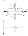
- Figure 1 shows a side view of a component 1 to subject the fracture separation is.
- the break should be made along the desired break line 3.
- the wedges 2a, 2b set either punctiform or linear with a sharp point or edge on the desired break line 3, so the Circumferential line of the desired fracture surface. They are directed towards each other arranged on opposite sides of the component 1, so that the maximum the compressive stress generated in the plane of the desired fracture surface lies, which has a perpendicular acting tensile stress.
- the wedges 2a, 2b there at the break line 3 to attack where due to design features a deviation the actual break line of the desired break line 3 to be expected or determined by experiments.
- the application of compressive forces by means of the wedges 2a, 2b can be made so that both wedges 2a, 2b via a drive (not shown) Actively act on the component with the same force. It is, of course, too possible to actively apply the force via the drive of only a first wedge 2a, while the second wedge 2b serves as a passive abutment. It is also conceivable serving as abutment second wedge 2b by serving as an abutment To replace bearing surface (not shown), or the function of the abutment in to lay a clamping (not shown) of the component.
- the tensile stress generated by the compressive stress, acting perpendicular to this follows the tensile stress curve 4 and represents on the one hand a stress on the component 1, which corresponds to the effect of a notch in the direction of the desired fracture surface and on the other hand a stress in their effect of a bias of the component. 1 in the direction perpendicular to the desired fracture surface, as would be caused by fictitious forces F 2 , F 2 ', with the difference that the fictitious forces F 2 , F 2 ' would create this state of stress throughout the component 1 and not only in a small Component area in the immediate vicinity of the desired fracture surface.
- the process of fracture separation proceeds in such a way that, on the part 1 to be subjected to fracture separation, the forces F 1 , F 1 'are initially applied along a part of the fracture line 3 by means of the wedges 2 a , 2 b. Under this state of stress then the actual fracture separation forces F 3 , F 3 ', applied perpendicular to the desired fracture surface on the component 1, which tearing the component 1 along the breaking line 3 in the parts 1 a, 1 b.
- the starting cracks initiating the fracture develop in such a way that they follow the stress maximum, as a result of which migration of the fracture surface into other regions of the component 1 can be largely prevented.
- the stress state of the component 1 during the fracture separation process also reduces the forces necessary for fracture separation, which, as already stated, can be used to increase the rate of increase of the forces F 3 , F 3 '.
- the forces F 1 , F 1 'in a dynamic process, during the fracture separation process, ie at the same time with the fracture separation forces F 3 , F 3 ' are applied to the component 1. It should be noted that the forces F 1 , F 1 'and the fracture separation forces F 3 , F 3 ' reach the maximum causing the fracture separation substantially at the same time.
- FIG. 1 Another possibility of applying a compressive stress to the part to be subjected to fracture separation in the region of the fracture surface is shown in FIG.
- a shear arrangement consisting of two shear jaws 5a, 5b and an abutment 5c, engages with its shearing edges 6a, 6b along a part of the breaking line 3, which here also corresponds to the circumferential line of the desired breaking surface, on the component 1.
- On the shearaws 5a, 5b act forces F 4 , F 4 'which generate a compressive stress in the component 1, which has its maximum in the range of the desired fracture surface.
- the tensile stress generated by the compressive stress has the same effects as described in connection with FIG.
- FIG. 3 shows an arrangement with the component 1 used by way of example, which is subjected to a three-point bending stress. In this case acts via a sharp-edged wedge 2a, which acts along part of the breaking line 3 on the component 1, a compressive force F 5 in the direction of the plane of the desired fracture surface.
- the fracture process itself proceeds from the fact that first on the component 1, on the sharp-edged wedge 7a, by the pressing force F 5 and the wedge-shaped systems 7b , 7c a bending stress and with this a tensile stress is applied.As stated, lies the maximum The tensile stress in the line 8.
- notches are made in a known way, e.g. by melting the Surface by laser beam, by mechanical scribing, by structural transformation etc. produced in the fracture separation to be subjected to component and support fracture separation especially of tough materials, e.g. ductile steels, such as those used in forged connecting rods.
- notches can also be advantageously achieved with the arrangement described in connection with FIG. 1 by dimensioning the pressure forces F 1 , F 1 'such that, as shown in FIG 9a, 9b of the wedges 2a, 2b penetrate into the surface of the component 1, so that in addition to the desired state of stress also a crack triggering favorable notch arises.
Landscapes
- Engineering & Computer Science (AREA)
- Mechanical Engineering (AREA)
- Life Sciences & Earth Sciences (AREA)
- Forests & Forestry (AREA)
- Shafts, Cranks, Connecting Bars, And Related Bearings (AREA)
- Perforating, Stamping-Out Or Severing By Means Other Than Cutting (AREA)
- Shearing Machines (AREA)
- Investigating Strength Of Materials By Application Of Mechanical Stress (AREA)
- Automatic Assembly (AREA)
- Reinforcement Elements For Buildings (AREA)
- Sampling And Sample Adjustment (AREA)
- Processing And Handling Of Plastics And Other Materials For Molding In General (AREA)
- Separation Using Semi-Permeable Membranes (AREA)
- Connection Of Plates (AREA)
Abstract
Description
- Fig.
- 1 eine Methode, die Druckkraft über Keile aufzubringen
- Fig. 2
- eine Methode, die Druckkraft über eine Scheranordnung aufzubringen
- Fig. 3
- eine Methode, die Druckkraft über eine Dreipunkt-Biegeanordnung aufzubringen
- Fig. 4
- eine Methode, die Druckkraft über Keile bei gleichzeitiger geringfügiger Oberflächenverformung aufzubringen.
Claims (10)
- Verfahren zum Bruchtrennen wieder zusammensetzbarer Bauteile oder deren Vormaterialien, wobei das der Bruchtrennung zu unterwerfende Bauteil durch das Aufbringen einer Bruchtrennkraft senkrecht zur gewünschten Bruchtrennfläche, bruchgetrennt wird, dadurch gekennzeichnet, dass vor dem Aufbringen der Bruchtrennkraft (F3, F3') eine Druckkraft ( F1 bis F6') auf das Bauteil (1) aufgebracht wird, die eine Zugspannung zur Folge hat die ihr Maximum in der Ebene der gewünschten Bruchtrennfläche senkrecht zu dieser hat, wobei die Druckkraft ( F1 bis F6') so bemessen ist, dass das durch sie erzeugte Spannungsniveau noch unterhalb der Streckgrenze des Werkstoffes des Bauteiles (1) liegt, und wobei die Druckkraft (F1 bis F6') im Augenblick des Aufbringens der Bruchtrennkraft (F3, F3') noch am Bauteil (1) ansteht.
- Verfahren zum Bruchtrennen wieder zusammensetzbarer Bauteile oder deren Vormaterialien, wobei in das der Bruchtrennung zu unterwerfende Bauteil entlang zumindest eines Teils der gewünschten Bruchlinie eine Kerbwirkung durch mechanische und/oder gefügeverändernde Einwirkung auf das Bauteil in dieses eingebracht wird und das Bauteil sodann, durch das Aufbringen einer Bruchtrennkraft senkrecht zur gewünschten Bruchtrennfläche, bruchgetrennt wird, dadurch gekennzeichnet, dass vor den Aufbringen der Bruchtrennkraft (F3, F3') eine Druckkraft (F1 bis F6') auf das Bauteil (1) aufgebracht wird, die eine Zugspannung zur Folge hat, die ihr Maximum in der Ebene der gewünschten Bruchtrennfläche senkrecht zu dieser hat, wobei die Druckkraft (F1 bis F6') so bemessen ist, dass das durch sie erzeugte Spannungsniveau noch unterhalb der Streckgrenze des Werkstoffes des Bauteiles liegt, und wobei die Druckkraft (F1 bis F6') im Augenblick des Aufbringens der Bruchtrennkraft (F3, F3') noch am Bauteil (1) ansteht.
- Verfahren zum Bruchtrennen gemäß den Ansprüchen 1 oder 2, dadurch gekennzeichnet, dass die Druckkraft (F1 bis F6') mittels einer statischen Druckbelastung auf das der Bruchtrennung zu unterwerfende Bauteil (1) aufgebracht wird, wobei die Druckkraft (F1 bis F6') in der Ebene der Bruchtrennfläche liegend und/oder parallel zu dieser am Bauteil (1) angreift.
- Verfahren zum Bruchtrennen gemäß den Ansprüchen 1 oder 2, dadurch gekennzeichnet, dass die Druckkraft (F1 bis F6') mittels einer dynamischen Druckbelastung auf das der Bruchtrennung zu unterwerfende Bauteil (1) aufgebracht wird, wobei die Druckkraft (F1 bis F6') in der Ebene der Bruchtrennfläche liegend und/oder parallel zu dieser am Bauteil (1) angreift und ihr Maximum im wesentlichen zeitgleich mit dem Maximum der Bruchtrennkraft (F3, F3') erreicht.
- Verfahren zum Bruchtrennen nach einem der Ansprüche 3 oder 4, dadurch gekennzeichnet, dass die Druckkraft (F1, F1') über wenigstens einen scharfkantigen Keil (2a) entlang zumindest eines Teils der Umfangslinie der gewünschten Bruchfläche auf das der Bruchtrennung zu unterwerfende Bauteil (1) aufgebracht wird, wobei das Druckgegenlager durch einen dem scharfkantigen Keil gegenüberliegend an der Umfangslinie der gewünschten Bruchfläche angreifenden gleichartigen Keil (2b) oder eine Anlagefläche oder durch die Einspannung des der Bruchtrennung zu unterwerfenden Bauteils (1) gebildet ist.
- Verfahren zum Bruchtrennen gemäß den Ansprüchen 3 oder 4, dadurch gekennzeichnet, dass die Druckkraft (F4, F4') mittels einer Scheranordnung (5a, 5b, 5c) auf das der Bruchtrennung zu unterwerfende Bauteil (1) aufgebracht wird.
- Verfahren zum Bruchtrennen nach Anspruch 6, dadurch gekennzeichnet, dass eine erste Anlagefläche der Scheranordnung (5a, 5b, 5c) mit ihrer Scherkante (6a) entlang eines Teils der Umfangslinie der gewünschten Bruchfläche anliegend, sich in Richtung des ersten Endes des der Bruchtrennung zu unterwerfenden Bauteils (1) erstreckend am Bauteil (1) angreift und dieser ersten Anlagefläche gegenüberliegend eine zweite Anlagefläche der Scheranordnung (5a, 5b, 5c) mit ihrer Scherkante (6b) entlang eines Teils der Umfangslinie der gewünschten Bruchfläche anliegend, sich in Richtung des zweiten Endes des Bauteils (1) erstreckend am Bauteil (1) angreift, und das Bauteil (1) gegen Verkanten gesichert ist, so dass die Scheranordnung (5a, 5b, 5c) eine in der Ebene der gewünschten Bruchfläche liegende Druckspannung und mit dieser eine senkrecht dazu wirkende Zugspannung erzeugt.
- Verfahren zum Bruchtrennen gemäß den Ansprüchen 3 oder 4, dadurch gekennzeichnet, dass die Druckkraft mittels einer Biegeanordnung ( 7a, 7b, 7c) auf das der Bruchtrennung zu unterwerfende Bauteil (1) aufgebracht wird, derart, dass das Maximum der Biegebelastung in der Ebene der gewünschten Bruchfläche liegt.
- Verfahren zum Bruchtrennen gemäß Anspruch 8, dadurch gekennzeichnet, dass die Biegeanordnung (7a,7b, 7c) eine Dreipunkt-Biegeanordnung ist, derart, dass eines der die Biegebelastung aufbringenden Elemente einen entlang eines Teils der Umfangslinie der gewünschten Bruchfläche angreifenden scharfkantigen Keil (7a) aufweist und die beiden anderen die Biegebelastung aufbringenden Elemente gegenüber dem ersten Element auf der anderen Seite des der Bruchtrennung zu unterwerfenden Bauteils (1) in jeweils gleichem Abstand zur Umfangslinie auf beiden Seiten derselben am Bauteil (1) angreifen.
- Verfahren nach Anspruch 5, dadurch gekennzeichnet, dass die Druckkraft (F1, F1') so bemessen ist, dass wenigstens einer der scharfkantigen Keile (2a, 2b) in die Oberfläche des der Bruchtrennung zu unterwerfenden Bauteils (1) eindringt.
Applications Claiming Priority (2)
| Application Number | Priority Date | Filing Date | Title |
|---|---|---|---|
| DE102004020063 | 2004-04-24 | ||
| DE200410020063 DE102004020063A1 (de) | 2004-04-24 | 2004-04-24 | Verfahren zum Bruchtrennen wieder zusammensetzbarer Bauteile oder deren Vormaterialien |
Publications (2)
| Publication Number | Publication Date |
|---|---|
| EP1588791A1 true EP1588791A1 (de) | 2005-10-26 |
| EP1588791B1 EP1588791B1 (de) | 2007-07-04 |
Family
ID=34933912
Family Applications (1)
| Application Number | Title | Priority Date | Filing Date |
|---|---|---|---|
| EP20050003981 Expired - Lifetime EP1588791B1 (de) | 2004-04-24 | 2005-02-24 | Verfahren zum Bruchtrennen wieder zusammensetzbarer Bauteile |
Country Status (8)
| Country | Link |
|---|---|
| US (1) | US7814632B2 (de) |
| EP (1) | EP1588791B1 (de) |
| JP (1) | JP2005305646A (de) |
| KR (1) | KR101059700B1 (de) |
| CN (1) | CN1689775B (de) |
| AT (1) | ATE366159T1 (de) |
| DE (2) | DE102004020063A1 (de) |
| RU (1) | RU2380219C2 (de) |
Cited By (2)
| Publication number | Priority date | Publication date | Assignee | Title |
|---|---|---|---|---|
| EP1839790A1 (de) * | 2006-03-29 | 2007-10-03 | Fraunhofer-Gesellschaft zur Förderung der angewandten Forschung e.V. | Vorrichtung und Verfahren zum Bruchtrennen von Pleueln |
| CN106808174A (zh) * | 2016-04-05 | 2017-06-09 | 中国石油大学(华东) | 一种低应力高效离心棒材下料机 |
Families Citing this family (9)
| Publication number | Priority date | Publication date | Assignee | Title |
|---|---|---|---|---|
| US7885490B2 (en) * | 2008-03-10 | 2011-02-08 | Octrolix Bv | Optical chemical detector and method |
| ES2399376T3 (es) * | 2009-03-16 | 2013-04-01 | Alfing Kessler Sondermaschinen Gmbh | Procedimiento para ensamblar dos componentes de una pieza |
| DE102010012476A1 (de) * | 2010-03-24 | 2011-09-29 | Schaeffler Technologies Gmbh & Co. Kg | Trennbare Laufbahnhülsen |
| JP5614096B2 (ja) * | 2010-05-19 | 2014-10-29 | 日産自動車株式会社 | 回転電機のロータコアに埋込まれる永久磁石およびその製造方法 |
| JP6035024B2 (ja) * | 2012-01-10 | 2016-11-30 | 大同特殊鋼株式会社 | 非筒状の永久磁石の製造方法 |
| SE540292C2 (en) * | 2016-10-28 | 2018-05-22 | Stora Enso Oyj | Method of making a laminated wood product and such a laminated wood product |
| DE102017129237A1 (de) * | 2017-12-08 | 2019-06-13 | Thyssenkrupp Ag | Verfahren und Vorrichtung zum Schneiden eines Werkstücks |
| CN109079230B (zh) * | 2018-10-15 | 2024-04-12 | 浙江恒立数控科技股份有限公司 | 飞剪机锁刀机构 |
| CN114299668A (zh) * | 2021-08-26 | 2022-04-08 | 兰州石化职业技术学院 | 共享口罩机 |
Citations (7)
| Publication number | Priority date | Publication date | Assignee | Title |
|---|---|---|---|---|
| US3515326A (en) * | 1968-05-17 | 1970-06-02 | Hachiro Saito | Apparatus for cutting of steel bars |
| US3834772A (en) * | 1972-06-08 | 1974-09-10 | Torrington Co | Fractured bearing race |
| EP0491574A1 (de) * | 1990-12-19 | 1992-06-24 | Peerless of America, Inc. | Verfahren und Vorrichtung zum Trennen von Mikroextrusionen mit verschiedenen Wegen und dünnen Wänden |
| EP0661125A1 (de) * | 1993-12-23 | 1995-07-05 | Alfing Kessler Sondermaschinen GmbH | Vorrichtung zum Bruchtrennen von Pleueln |
| EP0985479A1 (de) * | 1998-08-30 | 2000-03-15 | Isuzu Motors Limited | Verfahren und Vorrichtung zum Brechen einer Pleuelstange |
| EP1153686A2 (de) * | 2000-05-10 | 2001-11-14 | Man Nutzfahrzeuge Ag | Verfahren zur Bruchtrennung in Bauteilen oder deren Vormaterial |
| US6644529B1 (en) * | 1999-10-13 | 2003-11-11 | Sameh Hakim Andrawes Guirgis | Process to fracture connecting rods and the like with resonance-fatigue |
Family Cites Families (14)
| Publication number | Priority date | Publication date | Assignee | Title |
|---|---|---|---|---|
| US1366063A (en) * | 1915-11-29 | 1921-01-18 | Hydraulic Pressed Steel Co | Process of severing bars |
| US1209250A (en) * | 1916-04-26 | 1916-12-19 | Pierre Victor Leon Bellanger | Process of breaking steel bars. |
| US2630174A (en) * | 1948-12-07 | 1953-03-03 | Stephen W Poteet | Method of and means for cutting tubing |
| US3845895A (en) * | 1974-02-28 | 1974-11-05 | Nagoya Metal Co Ltd | Apparatus for cracking castings |
| JPS602533B2 (ja) * | 1975-12-25 | 1985-01-22 | エヌ・テー・エヌ東洋ベアリング株式会社 | 分割軸受リングの製作方法 |
| JPS60150904A (ja) * | 1984-01-12 | 1985-08-08 | Ube Ind Ltd | 押込切断装置 |
| DE58906379D1 (de) * | 1989-05-10 | 1994-01-20 | Kessler Kg Maschf | Verfahren und Vorrichtung zum Bruchtrennen von Pleueln. |
| ES2048229T3 (es) | 1989-05-10 | 1994-03-16 | Kessler Kg Maschf | Procedimiento y dispositivo para la separacion por rotura de bielas articuladas. |
| US4970783A (en) * | 1989-12-14 | 1990-11-20 | Ford Motor Company | Method of making split remateable connecting rod portions |
| DE4316354C2 (de) * | 1993-05-15 | 1996-07-18 | Grob Gmbh & Co Kg | Verfahren und Vorrichtung zum Bruchtrennen von Pleueln |
| US5988649A (en) * | 1997-05-01 | 1999-11-23 | E. I. Du Pont De Nemours And Company | Fractured seal ring |
| RU2191100C2 (ru) * | 2000-07-03 | 2002-10-20 | Открытое акционерное общество "АВТОВАЗ" | Устройство для отделения крышки нижней головки шатуна |
| RU2179921C1 (ru) * | 2000-07-17 | 2002-02-27 | Открытое акционерное общество "ГАЗ" | Устройство для разрыва нижней головки шатуна |
| DE10137975A1 (de) | 2001-08-08 | 2003-02-20 | Mauser Werke Oberndorf Maschb | Einrichtung und Verfahren zum Bruchtrennen von Werkstücken |
-
2004
- 2004-04-24 DE DE200410020063 patent/DE102004020063A1/de not_active Withdrawn
-
2005
- 2005-02-24 EP EP20050003981 patent/EP1588791B1/de not_active Expired - Lifetime
- 2005-02-24 AT AT05003981T patent/ATE366159T1/de active
- 2005-02-24 DE DE200550000954 patent/DE502005000954D1/de not_active Expired - Lifetime
- 2005-04-22 KR KR1020050033591A patent/KR101059700B1/ko not_active Expired - Fee Related
- 2005-04-22 RU RU2005112103A patent/RU2380219C2/ru active
- 2005-04-22 US US11/112,613 patent/US7814632B2/en active Active
- 2005-04-25 JP JP2005126534A patent/JP2005305646A/ja not_active Withdrawn
- 2005-04-25 CN CN200510066905XA patent/CN1689775B/zh not_active Expired - Lifetime
Patent Citations (7)
| Publication number | Priority date | Publication date | Assignee | Title |
|---|---|---|---|---|
| US3515326A (en) * | 1968-05-17 | 1970-06-02 | Hachiro Saito | Apparatus for cutting of steel bars |
| US3834772A (en) * | 1972-06-08 | 1974-09-10 | Torrington Co | Fractured bearing race |
| EP0491574A1 (de) * | 1990-12-19 | 1992-06-24 | Peerless of America, Inc. | Verfahren und Vorrichtung zum Trennen von Mikroextrusionen mit verschiedenen Wegen und dünnen Wänden |
| EP0661125A1 (de) * | 1993-12-23 | 1995-07-05 | Alfing Kessler Sondermaschinen GmbH | Vorrichtung zum Bruchtrennen von Pleueln |
| EP0985479A1 (de) * | 1998-08-30 | 2000-03-15 | Isuzu Motors Limited | Verfahren und Vorrichtung zum Brechen einer Pleuelstange |
| US6644529B1 (en) * | 1999-10-13 | 2003-11-11 | Sameh Hakim Andrawes Guirgis | Process to fracture connecting rods and the like with resonance-fatigue |
| EP1153686A2 (de) * | 2000-05-10 | 2001-11-14 | Man Nutzfahrzeuge Ag | Verfahren zur Bruchtrennung in Bauteilen oder deren Vormaterial |
Cited By (3)
| Publication number | Priority date | Publication date | Assignee | Title |
|---|---|---|---|---|
| EP1839790A1 (de) * | 2006-03-29 | 2007-10-03 | Fraunhofer-Gesellschaft zur Förderung der angewandten Forschung e.V. | Vorrichtung und Verfahren zum Bruchtrennen von Pleueln |
| CN106808174A (zh) * | 2016-04-05 | 2017-06-09 | 中国石油大学(华东) | 一种低应力高效离心棒材下料机 |
| CN106808174B (zh) * | 2016-04-05 | 2019-01-25 | 中国石油大学(华东) | 一种低应力高效离心棒材下料机 |
Also Published As
| Publication number | Publication date |
|---|---|
| DE102004020063A1 (de) | 2005-11-17 |
| ATE366159T1 (de) | 2007-07-15 |
| KR101059700B1 (ko) | 2011-08-29 |
| KR20060047418A (ko) | 2006-05-18 |
| EP1588791B1 (de) | 2007-07-04 |
| CN1689775B (zh) | 2010-09-29 |
| RU2380219C2 (ru) | 2010-01-27 |
| JP2005305646A (ja) | 2005-11-04 |
| CN1689775A (zh) | 2005-11-02 |
| US20050236455A1 (en) | 2005-10-27 |
| DE502005000954D1 (de) | 2007-08-16 |
| RU2005112103A (ru) | 2006-10-27 |
| US7814632B2 (en) | 2010-10-19 |
Similar Documents
| Publication | Publication Date | Title |
|---|---|---|
| DE69226463T2 (de) | Verfahren zum Bruchtrennen von wiederzusammenstellbaren Pleueln | |
| EP2042249A1 (de) | Verfahren und Vorrichtung zum Herstellen von Stanzteilen mit weitgehend glatter Schnitt- und vergrösserter Funktionsfläche | |
| WO1995028573A1 (de) | Verfahren zum bruchtrennen des lagerdeckels einer mehrteiligen lageranordnung, insbesondere in kurbelgehäusen von brennkraftmaschinen | |
| EP1588791A1 (de) | Verfahren zum Bruchtrennen wieder zusammensetzbarer Bauteile | |
| EP0546270A1 (de) | Verfahren zum lokalen Umformen von sprödem Material | |
| EP3423210B1 (de) | Schmiedepresse und verfahren zum schmieden eines werkstücks in einer schmiedepresse | |
| DE4401674C2 (de) | Verfahren sowie Vorrichtung zum Lochen von Werkstücken | |
| DE102013202657A1 (de) | Verfahren zum thermischen Fügen von unrunden Funktionsbauteilen auf einer Welle | |
| EP1753578A1 (de) | Vorrichtung und verfahren zum bruchtrennen von werkstücken | |
| DE102005034306A1 (de) | Verfahren zur Herstellung eines Kolbens einer Brennkraftmaschine zur Bildung einer Bewehrung einer Brennraummulde des Kolbens | |
| DE2440353A1 (de) | Befestigungsbolzen | |
| DE102015014489A1 (de) | Werkstück aus teilgehärtetem Stahlblech | |
| DE69708777T2 (de) | Verfahren zum Ausschneiden eines Zuschnittteils aus einer Blechplatte | |
| AT521274B1 (de) | Verfahren zur Herstellung eines bruchgetrennten Pleuels | |
| EP1620220B1 (de) | Verfahren und vorrichtung zum bruchtrennen von lagerdeckeln | |
| DE102010030424A1 (de) | Steuerventil | |
| DE102018112056B9 (de) | Verfahren und Vorrichtung zum Schneiden eines Werkstücks | |
| DE102020126410A1 (de) | Hilfsvorrichtung zur Montage von Lagerschalen an Pleueldeckeln sowie Verfahren zur Herstellung eines Pleuels | |
| DE19906436A1 (de) | Bruchtrennbares Maschinen-Bauteil zur paßgenauen Wiedervereinigung über die Bruchtrennflächen, insbesondere einer lösbaren Wiedervereinigung | |
| EP1445053B1 (de) | Verfahren und Vorrichtung zum Brechen von scheiben- oder plattenartigen Werkstücken | |
| EP1839790B1 (de) | Vorrichtung und Verfahren zum Bruchtrennen von Pleueln | |
| DE102007011216B4 (de) | Verfahren und Vorrichtung zum Verbinden zweier Glaselemente | |
| DE60302332T2 (de) | Kraftstoffeinspritzventil mit einer Düsenplatte und geneigten Auslassöffnungen | |
| DE19959677B4 (de) | Verfahren und Vorrichtung zum Bruchtrennen von ringförmigen Werkstücken | |
| EP4359206A1 (de) | Radialpresse |
Legal Events
| Date | Code | Title | Description |
|---|---|---|---|
| PUAI | Public reference made under article 153(3) epc to a published international application that has entered the european phase |
Free format text: ORIGINAL CODE: 0009012 |
|
| AK | Designated contracting states |
Kind code of ref document: A1 Designated state(s): AT BE BG CH CY CZ DE DK EE ES FI FR GB GR HU IE IS IT LI LT LU MC NL PL PT RO SE SI SK TR |
|
| AX | Request for extension of the european patent |
Extension state: AL BA HR LV MK YU |
|
| 17P | Request for examination filed |
Effective date: 20051115 |
|
| AKX | Designation fees paid |
Designated state(s): AT BE BG CH CY CZ DE DK EE ES FI FR GB GR HU IE IS IT LI LT LU MC NL PL PT RO SE SI SK TR |
|
| 17Q | First examination report despatched |
Effective date: 20060208 |
|
| GRAP | Despatch of communication of intention to grant a patent |
Free format text: ORIGINAL CODE: EPIDOSNIGR1 |
|
| GRAS | Grant fee paid |
Free format text: ORIGINAL CODE: EPIDOSNIGR3 |
|
| GRAA | (expected) grant |
Free format text: ORIGINAL CODE: 0009210 |
|
| AK | Designated contracting states |
Kind code of ref document: B1 Designated state(s): AT BE BG CH CY CZ DE DK EE ES FI FR GB GR HU IE IS IT LI LT LU MC NL PL PT RO SE SI SK TR |
|
| REG | Reference to a national code |
Ref country code: GB Ref legal event code: FG4D Free format text: NOT ENGLISH |
|
| REG | Reference to a national code |
Ref country code: CH Ref legal event code: EP |
|
| REG | Reference to a national code |
Ref country code: IE Ref legal event code: FG4D Free format text: LANGUAGE OF EP DOCUMENT: GERMAN |
|
| REF | Corresponds to: |
Ref document number: 502005000954 Country of ref document: DE Date of ref document: 20070816 Kind code of ref document: P |
|
| GBT | Gb: translation of ep patent filed (gb section 77(6)(a)/1977) |
Effective date: 20070905 |
|
| REG | Reference to a national code |
Ref country code: SE Ref legal event code: TRGR |
|
| ET | Fr: translation filed | ||
| PG25 | Lapsed in a contracting state [announced via postgrant information from national office to epo] |
Ref country code: PT Free format text: LAPSE BECAUSE OF FAILURE TO SUBMIT A TRANSLATION OF THE DESCRIPTION OR TO PAY THE FEE WITHIN THE PRESCRIBED TIME-LIMIT Effective date: 20071204 Ref country code: FI Free format text: LAPSE BECAUSE OF FAILURE TO SUBMIT A TRANSLATION OF THE DESCRIPTION OR TO PAY THE FEE WITHIN THE PRESCRIBED TIME-LIMIT Effective date: 20070704 Ref country code: BG Free format text: LAPSE BECAUSE OF FAILURE TO SUBMIT A TRANSLATION OF THE DESCRIPTION OR TO PAY THE FEE WITHIN THE PRESCRIBED TIME-LIMIT Effective date: 20071004 Ref country code: LT Free format text: LAPSE BECAUSE OF FAILURE TO SUBMIT A TRANSLATION OF THE DESCRIPTION OR TO PAY THE FEE WITHIN THE PRESCRIBED TIME-LIMIT Effective date: 20070704 Ref country code: ES Free format text: LAPSE BECAUSE OF FAILURE TO SUBMIT A TRANSLATION OF THE DESCRIPTION OR TO PAY THE FEE WITHIN THE PRESCRIBED TIME-LIMIT Effective date: 20071015 Ref country code: IS Free format text: LAPSE BECAUSE OF FAILURE TO SUBMIT A TRANSLATION OF THE DESCRIPTION OR TO PAY THE FEE WITHIN THE PRESCRIBED TIME-LIMIT Effective date: 20071104 Ref country code: SI Free format text: LAPSE BECAUSE OF FAILURE TO SUBMIT A TRANSLATION OF THE DESCRIPTION OR TO PAY THE FEE WITHIN THE PRESCRIBED TIME-LIMIT Effective date: 20070704 |
|
| PG25 | Lapsed in a contracting state [announced via postgrant information from national office to epo] |
Ref country code: PL Free format text: LAPSE BECAUSE OF FAILURE TO SUBMIT A TRANSLATION OF THE DESCRIPTION OR TO PAY THE FEE WITHIN THE PRESCRIBED TIME-LIMIT Effective date: 20070704 |
|
| REG | Reference to a national code |
Ref country code: IE Ref legal event code: FD4D |
|
| PG25 | Lapsed in a contracting state [announced via postgrant information from national office to epo] |
Ref country code: GR Free format text: LAPSE BECAUSE OF FAILURE TO SUBMIT A TRANSLATION OF THE DESCRIPTION OR TO PAY THE FEE WITHIN THE PRESCRIBED TIME-LIMIT Effective date: 20071005 Ref country code: DK Free format text: LAPSE BECAUSE OF FAILURE TO SUBMIT A TRANSLATION OF THE DESCRIPTION OR TO PAY THE FEE WITHIN THE PRESCRIBED TIME-LIMIT Effective date: 20070704 |
|
| PLBE | No opposition filed within time limit |
Free format text: ORIGINAL CODE: 0009261 |
|
| STAA | Information on the status of an ep patent application or granted ep patent |
Free format text: STATUS: NO OPPOSITION FILED WITHIN TIME LIMIT |
|
| PG25 | Lapsed in a contracting state [announced via postgrant information from national office to epo] |
Ref country code: SK Free format text: LAPSE BECAUSE OF FAILURE TO SUBMIT A TRANSLATION OF THE DESCRIPTION OR TO PAY THE FEE WITHIN THE PRESCRIBED TIME-LIMIT Effective date: 20070704 Ref country code: CZ Free format text: LAPSE BECAUSE OF FAILURE TO SUBMIT A TRANSLATION OF THE DESCRIPTION OR TO PAY THE FEE WITHIN THE PRESCRIBED TIME-LIMIT Effective date: 20070704 Ref country code: IE Free format text: LAPSE BECAUSE OF FAILURE TO SUBMIT A TRANSLATION OF THE DESCRIPTION OR TO PAY THE FEE WITHIN THE PRESCRIBED TIME-LIMIT Effective date: 20070704 |
|
| 26N | No opposition filed |
Effective date: 20080407 |
|
| PG25 | Lapsed in a contracting state [announced via postgrant information from national office to epo] |
Ref country code: RO Free format text: LAPSE BECAUSE OF FAILURE TO SUBMIT A TRANSLATION OF THE DESCRIPTION OR TO PAY THE FEE WITHIN THE PRESCRIBED TIME-LIMIT Effective date: 20070704 |
|
| BERE | Be: lapsed |
Owner name: MAN NUTZFAHRZEUGE A.G. Effective date: 20080228 |
|
| PG25 | Lapsed in a contracting state [announced via postgrant information from national office to epo] |
Ref country code: MC Free format text: LAPSE BECAUSE OF NON-PAYMENT OF DUE FEES Effective date: 20080228 |
|
| PG25 | Lapsed in a contracting state [announced via postgrant information from national office to epo] |
Ref country code: EE Free format text: LAPSE BECAUSE OF FAILURE TO SUBMIT A TRANSLATION OF THE DESCRIPTION OR TO PAY THE FEE WITHIN THE PRESCRIBED TIME-LIMIT Effective date: 20070704 |
|
| PG25 | Lapsed in a contracting state [announced via postgrant information from national office to epo] |
Ref country code: BE Free format text: LAPSE BECAUSE OF NON-PAYMENT OF DUE FEES Effective date: 20080228 |
|
| PG25 | Lapsed in a contracting state [announced via postgrant information from national office to epo] |
Ref country code: CY Free format text: LAPSE BECAUSE OF FAILURE TO SUBMIT A TRANSLATION OF THE DESCRIPTION OR TO PAY THE FEE WITHIN THE PRESCRIBED TIME-LIMIT Effective date: 20070704 |
|
| REG | Reference to a national code |
Ref country code: CH Ref legal event code: PL |
|
| PG25 | Lapsed in a contracting state [announced via postgrant information from national office to epo] |
Ref country code: LI Free format text: LAPSE BECAUSE OF NON-PAYMENT OF DUE FEES Effective date: 20090228 Ref country code: CH Free format text: LAPSE BECAUSE OF NON-PAYMENT OF DUE FEES Effective date: 20090228 |
|
| PG25 | Lapsed in a contracting state [announced via postgrant information from national office to epo] |
Ref country code: HU Free format text: LAPSE BECAUSE OF FAILURE TO SUBMIT A TRANSLATION OF THE DESCRIPTION OR TO PAY THE FEE WITHIN THE PRESCRIBED TIME-LIMIT Effective date: 20080105 Ref country code: LU Free format text: LAPSE BECAUSE OF NON-PAYMENT OF DUE FEES Effective date: 20080224 |
|
| PG25 | Lapsed in a contracting state [announced via postgrant information from national office to epo] |
Ref country code: TR Free format text: LAPSE BECAUSE OF FAILURE TO SUBMIT A TRANSLATION OF THE DESCRIPTION OR TO PAY THE FEE WITHIN THE PRESCRIBED TIME-LIMIT Effective date: 20070704 |
|
| REG | Reference to a national code |
Ref country code: NL Ref legal event code: TD Effective date: 20110304 |
|
| REG | Reference to a national code |
Ref country code: FR Ref legal event code: CD |
|
| REG | Reference to a national code |
Ref country code: DE Ref legal event code: R081 Ref document number: 502005000954 Country of ref document: DE Owner name: MAN TRUCK & BUS AG, DE Free format text: FORMER OWNER: MAN NUTZFAHRZEUGE AG, 80995 MUENCHEN, DE Effective date: 20110406 |
|
| REG | Reference to a national code |
Ref country code: FR Ref legal event code: PLFP Year of fee payment: 12 |
|
| REG | Reference to a national code |
Ref country code: FR Ref legal event code: PLFP Year of fee payment: 13 |
|
| REG | Reference to a national code |
Ref country code: FR Ref legal event code: PLFP Year of fee payment: 14 |
|
| REG | Reference to a national code |
Ref country code: DE Ref legal event code: R081 Ref document number: 502005000954 Country of ref document: DE Owner name: MAN TRUCK & BUS SE, DE Free format text: FORMER OWNER: MAN TRUCK & BUS AG, 80995 MUENCHEN, DE |
|
| PGFP | Annual fee paid to national office [announced via postgrant information from national office to epo] |
Ref country code: NL Payment date: 20240226 Year of fee payment: 20 |
|
| PGFP | Annual fee paid to national office [announced via postgrant information from national office to epo] |
Ref country code: AT Payment date: 20240220 Year of fee payment: 20 |
|
| PGFP | Annual fee paid to national office [announced via postgrant information from national office to epo] |
Ref country code: DE Payment date: 20240228 Year of fee payment: 20 Ref country code: GB Payment date: 20240220 Year of fee payment: 20 |
|
| PGFP | Annual fee paid to national office [announced via postgrant information from national office to epo] |
Ref country code: SE Payment date: 20240226 Year of fee payment: 20 Ref country code: IT Payment date: 20240222 Year of fee payment: 20 Ref country code: FR Payment date: 20240226 Year of fee payment: 20 |
|
| REG | Reference to a national code |
Ref country code: DE Ref legal event code: R071 Ref document number: 502005000954 Country of ref document: DE |
|
| REG | Reference to a national code |
Ref country code: NL Ref legal event code: MK Effective date: 20250223 |
|
| REG | Reference to a national code |
Ref country code: GB Ref legal event code: PE20 Expiry date: 20250223 |
|
| REG | Reference to a national code |
Ref country code: SE Ref legal event code: EUG |
|
| REG | Reference to a national code |
Ref country code: AT Ref legal event code: MK07 Ref document number: 366159 Country of ref document: AT Kind code of ref document: T Effective date: 20250224 |
|
| PG25 | Lapsed in a contracting state [announced via postgrant information from national office to epo] |
Ref country code: GB Free format text: LAPSE BECAUSE OF EXPIRATION OF PROTECTION Effective date: 20250223 |