EP1588683B1 - Dispositif pour monter des escaliers pour un fauteuil roulant - Google Patents
Dispositif pour monter des escaliers pour un fauteuil roulant Download PDFInfo
- Publication number
- EP1588683B1 EP1588683B1 EP05450071A EP05450071A EP1588683B1 EP 1588683 B1 EP1588683 B1 EP 1588683B1 EP 05450071 A EP05450071 A EP 05450071A EP 05450071 A EP05450071 A EP 05450071A EP 1588683 B1 EP1588683 B1 EP 1588683B1
- Authority
- EP
- European Patent Office
- Prior art keywords
- frame
- wheelchair
- bar
- stop
- transverse
- Prior art date
- Legal status (The legal status is an assumption and is not a legal conclusion. Google has not performed a legal analysis and makes no representation as to the accuracy of the status listed.)
- Expired - Lifetime
Links
Images



Classifications
-
- A—HUMAN NECESSITIES
- A61—MEDICAL OR VETERINARY SCIENCE; HYGIENE
- A61G—TRANSPORT, PERSONAL CONVEYANCES, OR ACCOMMODATION SPECIALLY ADAPTED FOR PATIENTS OR DISABLED PERSONS; OPERATING TABLES OR CHAIRS; CHAIRS FOR DENTISTRY; FUNERAL DEVICES
- A61G5/00—Chairs or personal conveyances specially adapted for patients or disabled persons, e.g. wheelchairs
- A61G5/06—Chairs or personal conveyances specially adapted for patients or disabled persons, e.g. wheelchairs with obstacle mounting facilities, e.g. for climbing stairs, kerbs or steps
- A61G5/061—Chairs or personal conveyances specially adapted for patients or disabled persons, e.g. wheelchairs with obstacle mounting facilities, e.g. for climbing stairs, kerbs or steps for climbing stairs
-
- B—PERFORMING OPERATIONS; TRANSPORTING
- B62—LAND VEHICLES FOR TRAVELLING OTHERWISE THAN ON RAILS
- B62B—HAND-PROPELLED VEHICLES, e.g. HAND CARTS OR PERAMBULATORS; SLEDGES
- B62B5/00—Accessories or details specially adapted for hand carts
- B62B5/02—Accessories or details specially adapted for hand carts providing for travelling up or down a flight of stairs
-
- Y—GENERAL TAGGING OF NEW TECHNOLOGICAL DEVELOPMENTS; GENERAL TAGGING OF CROSS-SECTIONAL TECHNOLOGIES SPANNING OVER SEVERAL SECTIONS OF THE IPC; TECHNICAL SUBJECTS COVERED BY FORMER USPC CROSS-REFERENCE ART COLLECTIONS [XRACs] AND DIGESTS
- Y10—TECHNICAL SUBJECTS COVERED BY FORMER USPC
- Y10S—TECHNICAL SUBJECTS COVERED BY FORMER USPC CROSS-REFERENCE ART COLLECTIONS [XRACs] AND DIGESTS
- Y10S280/00—Land vehicles
- Y10S280/10—Stair climbing chairs
Definitions
- the invention relates to a device for climbing stairs for a wheelchair with a lifting device having chassis and with recordings for the wheels of the wheelchair on transverse to the wheel axles arms laterally next to the chassis.
- Devices for climbing stairs for wheelchairs have a wheeled chassis, which receives a lifting device, for example with a liftable and lowerable support foot, which is placed on a tread and the chassis depending on the direction of travel to the next level raises or lowers.
- the control of the chassis is done by hand via a sliding guide with handles that carry control switch for actuating the electric drive of the lifting device.
- a bracket for receiving the chassis of the stair climbing device is provided on the chair frame, which is secured in the holder by means of a quick release.
- the wheels of the wheelchair for the use of stair climbing device must be removed.
- a stair climbing device In order to use a stair climbing device regardless of a holder for the chassis on the wheelchair, it is also known to attach to the chassis of the stair climbing device a support for two laterally adjacent to the chassis in the longitudinal direction extending arms, which are provided with receptacles for the wheels of the wheelchair So that a wheelchair can be pushed with its wheels in these shots and clamped to the sliding guide of the chassis of the stair climbing device by means of a simple clamping device.
- the wheelchair thus supports its wheels and the lateral arms load-bearing on the chassis of the stair climbing device with the advantage that the wheelchair no separate bracket for receiving the stair climbing device is provided and a removal of the wheels of the wheelchair for the use of stair climbing device is unnecessary.
- the invention is therefore based on the object, a device for climbing stairs for a wheelchair of the type described in such a way that despite the necessary for the Radabstützung of the wheelchair side delivery of the arms a space-saving transport position is made possible without having to remove the arms from the chassis.
- the invention solves the problem set by the fact that the arms each form at least one bracket which is pivotally mounted about a pivotally arranged in a frame transverse axis from a stop-limited Ausschwenklage in a pivoted against the frame position, and that hinged to the side of the chassis about a longitudinal axis Frame from a stop-limited, folded working position in a rest position is folded up.
- the arms with the recordings for the wheels of the wheelchair form at least one bracket, which is kept stop limited in its Ausschwenklage in a frame results in a sufficiently rigid construction for the load transfer to the chassis of the stair climbing device.
- the brackets are namely acted upon by the wheels of the wheelchair in the stop.
- brackets are provided for the two-sided arms for receiving the wheels, which are pivotally mounted at a mutual distance in the longitudinal direction of the chassis in a frame arranged transverse axes, so an adaptation to different diameter ranges of the wheels can be made possible.
- a frame-side wheel can come into effect, which has a tuned to the smaller wheel diameter, shorter distance to the wheel of the rear bracket.
- To insert the wheelchair in the wheel takes the chassis of the stair climbing device does not need to be tilted or only slightly tilted forward because of the pivoted-front bracket. Because of the mutual distance of the transverse axes for the storage of the two brackets of each arm, a shortening of the arms substantially to the frame length is ensured when swinging the bracket against the frame.
- brackets of the two-sided arms have two parallel webs mounted at a distance from one another on the transverse axes, which are connected at the end by spacers forming spacers.
- the webs of the bracket can form side guides for the wheels of the wheelchair in this case, and also provide advantageous conditions for a space-saving pivoting against each other two brackets, because for this purpose only the outer distance of the two webs of a bracket smaller than the inner spacing of the webs of the other of the two in To choose a frame mounted bracket is to allow the bracket when pivoting against the frame mesh. If the spacer of the respective front bracket is designed as Auffahrrampe for an impeller of the wheelchair, the insertion of the wheelchair in the lateral wheel is additionally facilitated.
- the bracket advantageous design conditions can be created when the stops for the two brackets of the two-sided arms each consist of a cross member of the frame, the cross member for the stop of the rear bracket outside and the cross member for the attack of the front, about the him receiving transverse axis out extended bracket between the two transverse axes for storage of the two brackets are.
- the lying between the two transverse axes for supporting the bracket cross member causes an extension of the front bracket over his him receiving transverse axis also to be effective for this bracket as a stop, but this cross bar can be advantageously used as a receptacle for an impeller of the wheelchair , This is not required for the cross member for striking the rear bracket. For this reason, this cross member is arranged outside the transverse axes for supporting the two brackets in order not to restrict the space required for pivoting the bracket against the frame space.
- the stair climbing device has a chassis 1 with two-sided wheels 2 and a lifting device, not shown, to raise or lower the device via attachable to the next step each support legs in a known manner to the next step.
- a lifting device not shown
- rollers 3 which are mounted on a pivotable about an axis 4 lever 5
- the unintentional rolling is prevented by a step, because with the falling of the rollers 3, the wheels 2 are braked.
- a sliding guide 6, which consists of a releasably connected to the chassis 1 spar, which is provided at its upper end with handles.
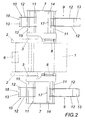
- each two brackets 9 and 10 are mounted pivotably about transverse axes 11. These brackets 9, 10 have two spaced apart webs 12, which are connected at their ends by spacers 13. The brackets 9, 10 strike in the pivoted position on transverse bars 14 and 15 of the frame 7 at. While the cross member 15 is located outside of the two transverse axes 11, the cross member 14 is disposed between the two transverse axes 11, which requires an extension of the bracket 9 on which they receiving transverse axis 11.
- the bracket 9, 10 from its swung-stop position against the Frame 7 are pivoted over each other, as indicated in Fig. 3.
- the front bracket 9 is shown pivoted against the frame 7 out.
- the pivoted bracket 9, 10 engage each other, so that the chassis 1 are widened only slightly by the folded up into the rest position frame 7.
- the chassis 1 is tilted forward to facilitate the front bracket 9 for pushing the wheels 16 of a wheelchair, not shown.
- the spacer 13 of the front bracket 9 forms a ramp, so that the wheels 16 can be rolled over this ramp to the receptacles 17 and 18, through the cross member 14 for the stop of the front bracket 9 and through the spacer 13 of rear bracket 10 formed and supplemented by the spacer 13 of the front bracket.
- the chassis 1, after insertion of the wheels 16 of a wheelchair in the bracket 9, 10 are clamped in a conventional manner by a clamping device on the sliding guide 6 to lift the wheelchair of FIG. 5 by Nachhintenkippen the chassis 1 and the chassis 1 or its lifting device 3 to proceed.
- the swung-out position of the front bracket 9 of FIGS. 4 and 5 is used only in wheelchairs with wheels in a larger diameter range. Impellers in a smaller diameter range do not need for their inclusion the swiveled front bracket 9.
- the front bracket 9 are therefore pivoted as shown in FIG. 1 for wheelchairs with smaller wheels from the dash-dotted lines indicated Ausschwenklage in the drawn with solid lines position against the frame 7, so that for receiving the wheels, the chassis 1 is not tilted forward needs.
- the recordings 17 and 18 are sufficient in this case the safe support of the wheelchair on its wheels when the wheelchair is clamped to the sliding guide 6 accordingly.
- FIGS. 6 and 7 The embodiment of FIGS. 6 and 7 is limited to the inclusion of wheelchairs, the wheels 16 manage without the front bracket 9, which is thus eliminated, which creates a particularly simple design conditions.
- the driving of the wheels 16 on the frame 7 for support on the receptacles 17, 18 is facilitated by an opening provided instead of the bracket 9 ramp 19 which is mounted stop limited pivotally about a transverse axis 20 of the frame 7, as shown in FIG. 7 taken can be.
- This ramp 19 is in the dash-dotted line in Fig. 7 indicated pivoted position on support levers 21 which are mounted on the transverse axis 20 and supported on a cross member 22.
- the ramp 19 with respect to the transverse axis 20 is a two-armed lever, the ramp is 19 swung when driving through the wheels 16 in the position shown in solid lines, so that if necessary, the transverse axis 20 can serve as a support for the wheels 16, which an increase in the impeller diameter compared to the receptacles 17, 18 allowed.
Landscapes
- Engineering & Computer Science (AREA)
- Health & Medical Sciences (AREA)
- Life Sciences & Earth Sciences (AREA)
- Animal Behavior & Ethology (AREA)
- General Health & Medical Sciences (AREA)
- Public Health (AREA)
- Veterinary Medicine (AREA)
- Chemical & Material Sciences (AREA)
- Combustion & Propulsion (AREA)
- Transportation (AREA)
- Mechanical Engineering (AREA)
- Handcart (AREA)
Claims (7)
- Dispositif pour monter des escaliers, pour un fauteuil roulant, avec un châssis (1) présentant un dispositif de levage et avec des logements pour les roues du fauteuil roulant, sur des bras s'étendant transversalement par rapport aux axes de roue, latéralement à côté du châssis (1), caractérisé en ce que les bras forment chacun au moins un étrier (10), monté de façon à pouvoir être manoeuvrés en pivotement autour d'un axe transversal (11) disposé dans un cadre (7), d'une position sortie par pivotement, limitée par une butée, en une position rétractée par pivotement, placée contre le cadre (7), et en ce que le cadre (7), articulé latéralement sur le châssis (1) autour d'un axe longitudinal (8), est susceptible d'être relevé par rabattement, d'une position de travail abaissée par rabattement, limitée par une butée, en une position de repos.
- Dispositif selon la revendication 1, caractérisé en ce que les bras forment chacun deux étriers (9, 10) montés à pivotement autour d'axes transversaux (11) disposés dans le cadre (7), selon un espacement mutuel dans la direction longitudinale du châssis (1).
- Dispositif selon la revendication 1 ou 2, caractérisé en ce que les étriers (9, 10) des bras situés des deux côtés présentent deux nervures (12) parallèles, montées à distance l'une de l'autre sur les axes transversaux (11), les nervures étant reliées côté extrémité par des supports d'espacement (13) formant des logements de roues (17).
- Dispositif selon les revendications 2 et 3, caractérisé en ce que l'espacement extérieur des deux nervures (12) d'un premier étrier (9) est inférieur à l'espacement intérieur des étriers (12) de l'autre des deux étriers (9, 10) montés dans le cadre (7).
- Dispositif selon l'une des revendications 2 à 4, caractérisé en ce que le support d'espacement (13), de l'étrier (9) situé chaque fois à l'avant, forme une rampe d'ascension.
- Dispositif selon la revendication 1, caractérisé en ce qu'une rampe d'ascension (19), réalisée sous forme de levier à deux bras, est montée dans le cadre (7), de façon à pouvoir pivoter en étant limitée par des butées autour d'un axe transversal (20) à distance en direction longitudinale du châssis (1), à l'avant de l'étrier (10).
- Dispositif selon l'une des revendications 2 à 5, caractérisé en ce que les butées des deux étriers (9, 10) des bras situés des deux côtés sont formées chacune d'un montant transversal (14, 15) du cadre (7), le montant transversal (15), pour la butée de l'étrier arrière (10), étant situé à l'extérieur, et le montant transversal (14), pour la butée de l'étrier avant (9) prolongé au-delà de l'axe transversal (11) le supportant, étant situé entre les deux axes transversaux (11) servant au montage en palier des deux étriers (9, 10).
Applications Claiming Priority (4)
| Application Number | Priority Date | Filing Date | Title |
|---|---|---|---|
| AT6702004 | 2004-04-19 | ||
| AT0067004A AT500566B8 (de) | 2004-04-19 | 2004-04-19 | Vorrichtung zum treppensteigen für einen rollstuhl |
| AT17602004 | 2004-10-20 | ||
| AT0176004A AT500567B8 (de) | 2004-04-19 | 2004-10-20 | Vorrichtung zum treppensteigen für einen rollstuhl |
Publications (2)
| Publication Number | Publication Date |
|---|---|
| EP1588683A1 EP1588683A1 (fr) | 2005-10-26 |
| EP1588683B1 true EP1588683B1 (fr) | 2007-05-23 |
Family
ID=34943324
Family Applications (1)
| Application Number | Title | Priority Date | Filing Date |
|---|---|---|---|
| EP05450071A Expired - Lifetime EP1588683B1 (fr) | 2004-04-19 | 2005-04-15 | Dispositif pour monter des escaliers pour un fauteuil roulant |
Country Status (4)
| Country | Link |
|---|---|
| US (1) | US7080842B2 (fr) |
| EP (1) | EP1588683B1 (fr) |
| AT (2) | AT500566B8 (fr) |
| DE (1) | DE502005000741D1 (fr) |
Families Citing this family (7)
| Publication number | Priority date | Publication date | Assignee | Title |
|---|---|---|---|---|
| NL1030428C2 (nl) * | 2005-11-15 | 2007-05-16 | A & M Consultancy & Invest B V | Rolstoel. |
| EP1970037A1 (fr) * | 2007-03-12 | 2008-09-17 | Wandeler Konrad | Véhicule de transport d'un fauteuil roulant |
| US20090267310A1 (en) * | 2008-04-24 | 2009-10-29 | Parkhurst Sr David L | Wheelchair lift assist device |
| CN109662845A (zh) * | 2017-10-16 | 2019-04-23 | 苏州艾尔楠医疗器械有限公司 | 一种轮椅车对接装置 |
| KR102373539B1 (ko) | 2019-11-22 | 2022-03-10 | 한국산업기술대학교산학협력단 | 계단 및 단차 지형의 휠체어 주행을 위한 전동 어시스트 모듈 |
| KR102371922B1 (ko) | 2019-11-22 | 2022-03-10 | 한국산업기술대학교산학협력단 | 계단 및 단차 지형의 휠체어 주행을 위한 전동 어시스트 모듈을 포함한 전동 어시스트 시스템 및 전동 어시스트 모듈의 제어 방법 |
| KR102366931B1 (ko) | 2020-07-02 | 2022-02-24 | 한국산업기술대학교산학협력단 | 평지 진입 구간의 감지가 가능한 전동 어시스트 모듈 |
Family Cites Families (5)
| Publication number | Priority date | Publication date | Assignee | Title |
|---|---|---|---|---|
| US3052323A (en) * | 1961-03-24 | 1962-09-04 | Grand Specialties Company | Lift truck |
| DE3530695C1 (de) * | 1985-08-28 | 1987-04-02 | Kleindienst Gmbh | Treppenraupe |
| JPH023985Y2 (fr) * | 1986-06-05 | 1990-01-30 | ||
| US5277436A (en) * | 1992-06-16 | 1994-01-11 | Magline, Inc. | Combination hand truck and stair ramp |
| GB9300350D0 (en) * | 1993-01-09 | 1993-03-03 | Rolac Ltd | Moving wheelchairs |
-
2004
- 2004-04-19 AT AT0067004A patent/AT500566B8/de not_active IP Right Cessation
- 2004-10-20 AT AT0176004A patent/AT500567B8/de not_active IP Right Cessation
-
2005
- 2005-04-15 EP EP05450071A patent/EP1588683B1/fr not_active Expired - Lifetime
- 2005-04-15 DE DE502005000741T patent/DE502005000741D1/de not_active Expired - Lifetime
- 2005-04-19 US US11/109,112 patent/US7080842B2/en not_active Expired - Fee Related
Also Published As
| Publication number | Publication date |
|---|---|
| AT500567B8 (de) | 2007-02-15 |
| AT500567B1 (de) | 2006-07-15 |
| AT500567A1 (de) | 2006-02-15 |
| AT500566A1 (de) | 2006-02-15 |
| AT500566B8 (de) | 2007-02-15 |
| EP1588683A1 (fr) | 2005-10-26 |
| AT500566B1 (de) | 2006-07-15 |
| DE502005000741D1 (de) | 2007-07-05 |
| US20050248105A1 (en) | 2005-11-10 |
| US7080842B2 (en) | 2006-07-25 |
Similar Documents
| Publication | Publication Date | Title |
|---|---|---|
| DE102019213710B4 (de) | Handwagen | |
| EP3030471B2 (fr) | Chariot transporteur pliable | |
| DE2833643C2 (de) | Transportwagen | |
| WO2003070538A1 (fr) | Transpalette | |
| DE2659602A1 (de) | Transportwagen, insbesondere krankentransportwagen | |
| DE102007047702A1 (de) | Kinderwagen mit einem zusammenklappbaren Fahrgestell | |
| EP1588683B1 (fr) | Dispositif pour monter des escaliers pour un fauteuil roulant | |
| EP3721953A1 (fr) | Planche à roulettes convertible | |
| EP0609663B1 (fr) | Chariot d'achats | |
| DE3515808C2 (fr) | ||
| EP2875889B1 (fr) | Scie à onglet et/ou à tirer | |
| DE102009040850B4 (de) | Holzspalter | |
| DE102020108026B3 (de) | Transportvorrichtung für eine Rüttelplatte | |
| DE4206853C2 (de) | Zweirädriges Transport- und Abrollgerät für Materialrollen | |
| DE2127309A1 (de) | Durchlaufregal | |
| DE3412755A1 (de) | Ausfahrbares fahrwerk fuer einen standkoerper | |
| DE4430841C2 (de) | Stapelbarer Transportwagen | |
| AT411666B (de) | Verfahren zum abnehmen und abstellen eines auswechselbaren aufbaus vom chassis eines lastkraftwagens und lastkraftwagen mit einem auswechselbaren aufbau | |
| DE640036C (de) | Aus herablassbaren Gleitkufen bestehende Vorrichtung an Kinderwagen zu deren Befoerderung ueber Treppen | |
| DE3138542A1 (de) | "fasskipp- und -fahrbock" | |
| DE4312392A1 (de) | Einkaufswagen | |
| DE102007052914A1 (de) | Wagen, insbesondere Handwagen | |
| WO2007009604A1 (fr) | Rayonnage | |
| DE3904621C2 (fr) | ||
| AT368460B (de) | Abschiebevorrichtung fuer einen eine am unteren ende eines rahmens befestigte schaufel aufweisenden zweiraedrigen stapelkarren |
Legal Events
| Date | Code | Title | Description |
|---|---|---|---|
| PUAI | Public reference made under article 153(3) epc to a published international application that has entered the european phase |
Free format text: ORIGINAL CODE: 0009012 |
|
| AK | Designated contracting states |
Kind code of ref document: A1 Designated state(s): AT BE BG CH CY CZ DE DK EE ES FI FR GB GR HU IE IS IT LI LT LU MC NL PL PT RO SE SI SK TR |
|
| AX | Request for extension of the european patent |
Extension state: AL BA HR LV MK YU |
|
| 17P | Request for examination filed |
Effective date: 20060309 |
|
| AKX | Designation fees paid |
Designated state(s): DE FR GB IT |
|
| GRAP | Despatch of communication of intention to grant a patent |
Free format text: ORIGINAL CODE: EPIDOSNIGR1 |
|
| GRAS | Grant fee paid |
Free format text: ORIGINAL CODE: EPIDOSNIGR3 |
|
| GRAA | (expected) grant |
Free format text: ORIGINAL CODE: 0009210 |
|
| AK | Designated contracting states |
Kind code of ref document: B1 Designated state(s): DE FR GB IT |
|
| REG | Reference to a national code |
Ref country code: GB Ref legal event code: FG4D Free format text: NOT ENGLISH |
|
| REF | Corresponds to: |
Ref document number: 502005000741 Country of ref document: DE Date of ref document: 20070705 Kind code of ref document: P |
|
| GBT | Gb: translation of ep patent filed (gb section 77(6)(a)/1977) |
Effective date: 20070814 |
|
| ET | Fr: translation filed | ||
| PLBE | No opposition filed within time limit |
Free format text: ORIGINAL CODE: 0009261 |
|
| STAA | Information on the status of an ep patent application or granted ep patent |
Free format text: STATUS: NO OPPOSITION FILED WITHIN TIME LIMIT |
|
| 26N | No opposition filed |
Effective date: 20080226 |
|
| PGFP | Annual fee paid to national office [announced via postgrant information from national office to epo] |
Ref country code: GB Payment date: 20120427 Year of fee payment: 8 |
|
| GBPC | Gb: european patent ceased through non-payment of renewal fee |
Effective date: 20130415 |
|
| PG25 | Lapsed in a contracting state [announced via postgrant information from national office to epo] |
Ref country code: GB Free format text: LAPSE BECAUSE OF NON-PAYMENT OF DUE FEES Effective date: 20130415 |
|
| REG | Reference to a national code |
Ref country code: FR Ref legal event code: PLFP Year of fee payment: 11 |
|
| REG | Reference to a national code |
Ref country code: FR Ref legal event code: PLFP Year of fee payment: 12 |
|
| REG | Reference to a national code |
Ref country code: FR Ref legal event code: PLFP Year of fee payment: 13 |
|
| REG | Reference to a national code |
Ref country code: FR Ref legal event code: PLFP Year of fee payment: 14 |
|
| PGFP | Annual fee paid to national office [announced via postgrant information from national office to epo] |
Ref country code: IT Payment date: 20200424 Year of fee payment: 16 |
|
| PGFP | Annual fee paid to national office [announced via postgrant information from national office to epo] |
Ref country code: FR Payment date: 20220427 Year of fee payment: 18 |
|
| PG25 | Lapsed in a contracting state [announced via postgrant information from national office to epo] |
Ref country code: IT Free format text: LAPSE BECAUSE OF NON-PAYMENT OF DUE FEES Effective date: 20200415 |
|
| PG25 | Lapsed in a contracting state [announced via postgrant information from national office to epo] |
Ref country code: FR Free format text: LAPSE BECAUSE OF NON-PAYMENT OF DUE FEES Effective date: 20230430 |
|
| PGFP | Annual fee paid to national office [announced via postgrant information from national office to epo] |
Ref country code: DE Payment date: 20240429 Year of fee payment: 20 |
|
| REG | Reference to a national code |
Ref country code: DE Ref legal event code: R071 Ref document number: 502005000741 Country of ref document: DE |
|
| PG25 | Lapsed in a contracting state [announced via postgrant information from national office to epo] |
Ref country code: IT Free format text: LAPSE BECAUSE OF NON-PAYMENT OF DUE FEES Effective date: 20210415 |