EP1587883B1 - Verfahren zur oberflächenmodifizierung von anorganischen oxidpulvern, pulver die nach diesem verfahren hergestellt wurden und verwendung derselben - Google Patents
Verfahren zur oberflächenmodifizierung von anorganischen oxidpulvern, pulver die nach diesem verfahren hergestellt wurden und verwendung derselben Download PDFInfo
- Publication number
- EP1587883B1 EP1587883B1 EP04704755.0A EP04704755A EP1587883B1 EP 1587883 B1 EP1587883 B1 EP 1587883B1 EP 04704755 A EP04704755 A EP 04704755A EP 1587883 B1 EP1587883 B1 EP 1587883B1
- Authority
- EP
- European Patent Office
- Prior art keywords
- powder
- particles
- particle size
- surface modification
- gas
- Prior art date
- Legal status (The legal status is an assumption and is not a legal conclusion. Google has not performed a legal analysis and makes no representation as to the accuracy of the status listed.)
- Expired - Lifetime
Links
- 239000000843 powder Substances 0.000 title claims description 362
- 238000002715 modification method Methods 0.000 title claims description 23
- 229910052809 inorganic oxide Inorganic materials 0.000 title claims description 14
- 238000000034 method Methods 0.000 title description 42
- 239000002245 particle Substances 0.000 claims description 178
- 239000007789 gas Substances 0.000 claims description 81
- 239000000203 mixture Substances 0.000 claims description 59
- 239000012159 carrier gas Substances 0.000 claims description 28
- -1 ethylene, propylene, acetylene Chemical group 0.000 claims description 18
- 238000003921 particle size analysis Methods 0.000 claims description 11
- 239000013078 crystal Substances 0.000 claims description 9
- 229910052719 titanium Inorganic materials 0.000 claims description 8
- ATUOYWHBWRKTHZ-UHFFFAOYSA-N Propane Chemical compound CCC ATUOYWHBWRKTHZ-UHFFFAOYSA-N 0.000 claims description 6
- 229910052782 aluminium Inorganic materials 0.000 claims description 6
- VNWKTOKETHGBQD-UHFFFAOYSA-N methane Chemical compound C VNWKTOKETHGBQD-UHFFFAOYSA-N 0.000 claims description 6
- UGFAIRIUMAVXCW-UHFFFAOYSA-N Carbon monoxide Chemical compound [O+]#[C-] UGFAIRIUMAVXCW-UHFFFAOYSA-N 0.000 claims description 3
- OTMSDBZUPAUEDD-UHFFFAOYSA-N Ethane Chemical compound CC OTMSDBZUPAUEDD-UHFFFAOYSA-N 0.000 claims description 3
- UFHFLCQGNIYNRP-UHFFFAOYSA-N Hydrogen Chemical compound [H][H] UFHFLCQGNIYNRP-UHFFFAOYSA-N 0.000 claims description 3
- 239000001273 butane Substances 0.000 claims description 3
- 229910052791 calcium Inorganic materials 0.000 claims description 3
- 229910002091 carbon monoxide Inorganic materials 0.000 claims description 3
- 239000001257 hydrogen Substances 0.000 claims description 3
- 229910052739 hydrogen Inorganic materials 0.000 claims description 3
- 239000003915 liquefied petroleum gas Substances 0.000 claims description 3
- 229910052749 magnesium Inorganic materials 0.000 claims description 3
- IJDNQMDRQITEOD-UHFFFAOYSA-N n-butane Chemical compound CCCC IJDNQMDRQITEOD-UHFFFAOYSA-N 0.000 claims description 3
- OFBQJSOFQDEBGM-UHFFFAOYSA-N n-pentane Natural products CCCCC OFBQJSOFQDEBGM-UHFFFAOYSA-N 0.000 claims description 3
- 239000001294 propane Substances 0.000 claims description 3
- 239000000047 product Substances 0.000 description 53
- PNEYBMLMFCGWSK-UHFFFAOYSA-N aluminium oxide Inorganic materials [O-2].[O-2].[O-2].[Al+3].[Al+3] PNEYBMLMFCGWSK-UHFFFAOYSA-N 0.000 description 32
- 239000002994 raw material Substances 0.000 description 26
- 238000002485 combustion reaction Methods 0.000 description 21
- 239000003822 epoxy resin Substances 0.000 description 19
- 229920000647 polyepoxide Polymers 0.000 description 19
- 238000006243 chemical reaction Methods 0.000 description 18
- 239000000945 filler Substances 0.000 description 18
- VYPSYNLAJGMNEJ-UHFFFAOYSA-N Silicium dioxide Chemical compound O=[Si]=O VYPSYNLAJGMNEJ-UHFFFAOYSA-N 0.000 description 16
- VSCWAEJMTAWNJL-UHFFFAOYSA-K aluminium trichloride Chemical compound Cl[Al](Cl)Cl VSCWAEJMTAWNJL-UHFFFAOYSA-K 0.000 description 16
- 239000001301 oxygen Substances 0.000 description 16
- 229910052760 oxygen Inorganic materials 0.000 description 16
- 229920005989 resin Polymers 0.000 description 16
- 239000011347 resin Substances 0.000 description 16
- QVGXLLKOCUKJST-UHFFFAOYSA-N atomic oxygen Chemical compound [O] QVGXLLKOCUKJST-UHFFFAOYSA-N 0.000 description 14
- 230000004048 modification Effects 0.000 description 14
- 238000012986 modification Methods 0.000 description 14
- GWEVSGVZZGPLCZ-UHFFFAOYSA-N Titan oxide Chemical compound O=[Ti]=O GWEVSGVZZGPLCZ-UHFFFAOYSA-N 0.000 description 13
- 229920000620 organic polymer Polymers 0.000 description 13
- 230000008569 process Effects 0.000 description 13
- 238000004519 manufacturing process Methods 0.000 description 12
- 239000011248 coating agent Substances 0.000 description 11
- 238000004898 kneading Methods 0.000 description 11
- 239000000463 material Substances 0.000 description 10
- 239000011230 binding agent Substances 0.000 description 9
- 229920005573 silicon-containing polymer Polymers 0.000 description 9
- 239000002537 cosmetic Substances 0.000 description 8
- 230000001105 regulatory effect Effects 0.000 description 8
- 239000000377 silicon dioxide Substances 0.000 description 8
- IJGRMHOSHXDMSA-UHFFFAOYSA-N Atomic nitrogen Chemical compound N#N IJGRMHOSHXDMSA-UHFFFAOYSA-N 0.000 description 7
- 239000003795 chemical substances by application Substances 0.000 description 7
- 238000000576 coating method Methods 0.000 description 7
- 238000009826 distribution Methods 0.000 description 7
- TWNQGVIAIRXVLR-UHFFFAOYSA-N oxo(oxoalumanyloxy)alumane Chemical compound O=[Al]O[Al]=O TWNQGVIAIRXVLR-UHFFFAOYSA-N 0.000 description 7
- 238000004381 surface treatment Methods 0.000 description 7
- 230000000694 effects Effects 0.000 description 6
- 239000010408 film Substances 0.000 description 6
- 239000010954 inorganic particle Substances 0.000 description 6
- 238000002844 melting Methods 0.000 description 6
- 230000008018 melting Effects 0.000 description 6
- 239000011369 resultant mixture Substances 0.000 description 6
- 239000012756 surface treatment agent Substances 0.000 description 6
- 239000010936 titanium Substances 0.000 description 6
- LFQSCWFLJHTTHZ-UHFFFAOYSA-N Ethanol Chemical compound CCO LFQSCWFLJHTTHZ-UHFFFAOYSA-N 0.000 description 5
- 238000001816 cooling Methods 0.000 description 5
- 235000014113 dietary fatty acids Nutrition 0.000 description 5
- 239000000194 fatty acid Substances 0.000 description 5
- 229930195729 fatty acid Natural products 0.000 description 5
- 239000000835 fiber Substances 0.000 description 5
- 239000003921 oil Substances 0.000 description 5
- 235000019198 oils Nutrition 0.000 description 5
- 230000001590 oxidative effect Effects 0.000 description 5
- 239000012071 phase Substances 0.000 description 5
- 238000000926 separation method Methods 0.000 description 5
- XJDNKRIXUMDJCW-UHFFFAOYSA-J titanium tetrachloride Chemical compound Cl[Ti](Cl)(Cl)Cl XJDNKRIXUMDJCW-UHFFFAOYSA-J 0.000 description 5
- MPDGHEJMBKOTSU-YKLVYJNSSA-N 18beta-glycyrrhetic acid Chemical compound C([C@H]1C2=CC(=O)[C@H]34)[C@@](C)(C(O)=O)CC[C@]1(C)CC[C@@]2(C)[C@]4(C)CC[C@@H]1[C@]3(C)CC[C@H](O)C1(C)C MPDGHEJMBKOTSU-YKLVYJNSSA-N 0.000 description 4
- 229920003171 Poly (ethylene oxide) Polymers 0.000 description 4
- 239000000654 additive Substances 0.000 description 4
- 230000000996 additive effect Effects 0.000 description 4
- 239000000919 ceramic Substances 0.000 description 4
- 230000000052 comparative effect Effects 0.000 description 4
- 150000002148 esters Chemical class 0.000 description 4
- 229910052751 metal Inorganic materials 0.000 description 4
- 239000002184 metal Substances 0.000 description 4
- 239000007787 solid Substances 0.000 description 4
- 238000007669 thermal treatment Methods 0.000 description 4
- CIWBSHSKHKDKBQ-JLAZNSOCSA-N Ascorbic acid Natural products OC[C@H](O)[C@H]1OC(=O)C(O)=C1O CIWBSHSKHKDKBQ-JLAZNSOCSA-N 0.000 description 3
- WVDDGKGOMKODPV-UHFFFAOYSA-N Benzyl alcohol Chemical compound OCC1=CC=CC=C1 WVDDGKGOMKODPV-UHFFFAOYSA-N 0.000 description 3
- 239000002202 Polyethylene glycol Substances 0.000 description 3
- DNIAPMSPPWPWGF-UHFFFAOYSA-N Propylene glycol Chemical compound CC(O)CO DNIAPMSPPWPWGF-UHFFFAOYSA-N 0.000 description 3
- 239000003963 antioxidant agent Substances 0.000 description 3
- 235000006708 antioxidants Nutrition 0.000 description 3
- KRKNYBCHXYNGOX-UHFFFAOYSA-N citric acid Chemical compound OC(=O)CC(O)(C(O)=O)CC(O)=O KRKNYBCHXYNGOX-UHFFFAOYSA-N 0.000 description 3
- 239000011246 composite particle Substances 0.000 description 3
- 239000011231 conductive filler Substances 0.000 description 3
- 230000001186 cumulative effect Effects 0.000 description 3
- 150000004665 fatty acids Chemical class 0.000 description 3
- 238000002156 mixing Methods 0.000 description 3
- 229910052757 nitrogen Inorganic materials 0.000 description 3
- 229920001223 polyethylene glycol Polymers 0.000 description 3
- 239000011541 reaction mixture Substances 0.000 description 3
- 239000003566 sealing material Substances 0.000 description 3
- 239000004065 semiconductor Substances 0.000 description 3
- 239000011734 sodium Substances 0.000 description 3
- 229910052708 sodium Inorganic materials 0.000 description 3
- PRAKJMSDJKAYCZ-UHFFFAOYSA-N squalane Chemical class CC(C)CCCC(C)CCCC(C)CCCCC(C)CCCC(C)CCCC(C)C PRAKJMSDJKAYCZ-UHFFFAOYSA-N 0.000 description 3
- 239000000126 substance Substances 0.000 description 3
- 229920002803 thermoplastic polyurethane Polymers 0.000 description 3
- 239000004408 titanium dioxide Substances 0.000 description 3
- 239000012808 vapor phase Substances 0.000 description 3
- PUPZLCDOIYMWBV-UHFFFAOYSA-N (+/-)-1,3-Butanediol Chemical compound CC(O)CCO PUPZLCDOIYMWBV-UHFFFAOYSA-N 0.000 description 2
- GVJHHUAWPYXKBD-UHFFFAOYSA-N (±)-α-Tocopherol Chemical compound OC1=C(C)C(C)=C2OC(CCCC(C)CCCC(C)CCCC(C)C)(C)CCC2=C1C GVJHHUAWPYXKBD-UHFFFAOYSA-N 0.000 description 2
- XDOFQFKRPWOURC-UHFFFAOYSA-N 16-methylheptadecanoic acid Chemical compound CC(C)CCCCCCCCCCCCCCC(O)=O XDOFQFKRPWOURC-UHFFFAOYSA-N 0.000 description 2
- KXGFMDJXCMQABM-UHFFFAOYSA-N 2-methoxy-6-methylphenol Chemical compound [CH]OC1=CC=CC([CH])=C1O KXGFMDJXCMQABM-UHFFFAOYSA-N 0.000 description 2
- ALYNCZNDIQEVRV-UHFFFAOYSA-N 4-aminobenzoic acid Chemical compound NC1=CC=C(C(O)=O)C=C1 ALYNCZNDIQEVRV-UHFFFAOYSA-N 0.000 description 2
- VTYYLEPIZMXCLO-UHFFFAOYSA-L Calcium carbonate Chemical compound [Ca+2].[O-]C([O-])=O VTYYLEPIZMXCLO-UHFFFAOYSA-L 0.000 description 2
- 229920002160 Celluloid Polymers 0.000 description 2
- 229920002101 Chitin Polymers 0.000 description 2
- FBPFZTCFMRRESA-FSIIMWSLSA-N D-Glucitol Natural products OC[C@H](O)[C@H](O)[C@@H](O)[C@H](O)CO FBPFZTCFMRRESA-FSIIMWSLSA-N 0.000 description 2
- FBPFZTCFMRRESA-JGWLITMVSA-N D-glucitol Chemical compound OC[C@H](O)[C@@H](O)[C@H](O)[C@H](O)CO FBPFZTCFMRRESA-JGWLITMVSA-N 0.000 description 2
- RGHNJXZEOKUKBD-SQOUGZDYSA-N D-gluconic acid Chemical compound OC[C@@H](O)[C@@H](O)[C@H](O)[C@@H](O)C(O)=O RGHNJXZEOKUKBD-SQOUGZDYSA-N 0.000 description 2
- YCKRFDGAMUMZLT-UHFFFAOYSA-N Fluorine atom Chemical compound [F] YCKRFDGAMUMZLT-UHFFFAOYSA-N 0.000 description 2
- PEDCQBHIVMGVHV-UHFFFAOYSA-N Glycerine Chemical compound OCC(O)CO PEDCQBHIVMGVHV-UHFFFAOYSA-N 0.000 description 2
- DHMQDGOQFOQNFH-UHFFFAOYSA-N Glycine Chemical compound NCC(O)=O DHMQDGOQFOQNFH-UHFFFAOYSA-N 0.000 description 2
- AEMRFAOFKBGASW-UHFFFAOYSA-N Glycolic acid Chemical compound OCC(O)=O AEMRFAOFKBGASW-UHFFFAOYSA-N 0.000 description 2
- MPDGHEJMBKOTSU-UHFFFAOYSA-N Glycyrrhetinsaeure Natural products C12C(=O)C=C3C4CC(C)(C(O)=O)CCC4(C)CCC3(C)C1(C)CCC1C2(C)CCC(O)C1(C)C MPDGHEJMBKOTSU-UHFFFAOYSA-N 0.000 description 2
- DGAQECJNVWCQMB-PUAWFVPOSA-M Ilexoside XXIX Chemical compound C[C@@H]1CC[C@@]2(CC[C@@]3(C(=CC[C@H]4[C@]3(CC[C@@H]5[C@@]4(CC[C@@H](C5(C)C)OS(=O)(=O)[O-])C)C)[C@@H]2[C@]1(C)O)C)C(=O)O[C@H]6[C@@H]([C@H]([C@@H]([C@H](O6)CO)O)O)O.[Na+] DGAQECJNVWCQMB-PUAWFVPOSA-M 0.000 description 2
- UQSXHKLRYXJYBZ-UHFFFAOYSA-N Iron oxide Chemical compound [Fe]=O UQSXHKLRYXJYBZ-UHFFFAOYSA-N 0.000 description 2
- KFZMGEQAYNKOFK-UHFFFAOYSA-N Isopropanol Chemical compound CC(C)O KFZMGEQAYNKOFK-UHFFFAOYSA-N 0.000 description 2
- 239000004640 Melamine resin Substances 0.000 description 2
- 229920000877 Melamine resin Polymers 0.000 description 2
- LRHPLDYGYMQRHN-UHFFFAOYSA-N N-Butanol Chemical compound CCCCO LRHPLDYGYMQRHN-UHFFFAOYSA-N 0.000 description 2
- 239000002033 PVDF binder Substances 0.000 description 2
- 239000004372 Polyvinyl alcohol Substances 0.000 description 2
- 229920001328 Polyvinylidene chloride Polymers 0.000 description 2
- 239000006087 Silane Coupling Agent Substances 0.000 description 2
- 229920002472 Starch Polymers 0.000 description 2
- RTAQQCXQSZGOHL-UHFFFAOYSA-N Titanium Chemical compound [Ti] RTAQQCXQSZGOHL-UHFFFAOYSA-N 0.000 description 2
- 229920001807 Urea-formaldehyde Polymers 0.000 description 2
- 238000000563 Verneuil process Methods 0.000 description 2
- XTXRWKRVRITETP-UHFFFAOYSA-N Vinyl acetate Chemical compound CC(=O)OC=C XTXRWKRVRITETP-UHFFFAOYSA-N 0.000 description 2
- 150000004703 alkoxides Chemical class 0.000 description 2
- 125000000217 alkyl group Chemical group 0.000 description 2
- POJWUDADGALRAB-UHFFFAOYSA-N allantoin Chemical compound NC(=O)NC1NC(=O)NC1=O POJWUDADGALRAB-UHFFFAOYSA-N 0.000 description 2
- 235000001014 amino acid Nutrition 0.000 description 2
- 150000001413 amino acids Chemical class 0.000 description 2
- 229940121363 anti-inflammatory agent Drugs 0.000 description 2
- 239000002260 anti-inflammatory agent Substances 0.000 description 2
- 230000003078 antioxidant effect Effects 0.000 description 2
- TZCXTZWJZNENPQ-UHFFFAOYSA-L barium sulfate Chemical compound [Ba+2].[O-]S([O-])(=O)=O TZCXTZWJZNENPQ-UHFFFAOYSA-L 0.000 description 2
- WPYMKLBDIGXBTP-UHFFFAOYSA-N benzoic acid Chemical compound OC(=O)C1=CC=CC=C1 WPYMKLBDIGXBTP-UHFFFAOYSA-N 0.000 description 2
- FUWUEFKEXZQKKA-UHFFFAOYSA-N beta-thujaplicin Chemical compound CC(C)C=1C=CC=C(O)C(=O)C=1 FUWUEFKEXZQKKA-UHFFFAOYSA-N 0.000 description 2
- 239000011575 calcium Substances 0.000 description 2
- 239000004359 castor oil Substances 0.000 description 2
- 235000019438 castor oil Nutrition 0.000 description 2
- 239000001913 cellulose Substances 0.000 description 2
- 229920002678 cellulose Polymers 0.000 description 2
- 239000002738 chelating agent Substances 0.000 description 2
- 239000002131 composite material Substances 0.000 description 2
- 239000007822 coupling agent Substances 0.000 description 2
- NOPFSRXAKWQILS-UHFFFAOYSA-N docosan-1-ol Chemical compound CCCCCCCCCCCCCCCCCCCCCCO NOPFSRXAKWQILS-UHFFFAOYSA-N 0.000 description 2
- UKMSUNONTOPOIO-UHFFFAOYSA-N docosanoic acid Chemical compound CCCCCCCCCCCCCCCCCCCCCC(O)=O UKMSUNONTOPOIO-UHFFFAOYSA-N 0.000 description 2
- POULHZVOKOAJMA-UHFFFAOYSA-N dodecanoic acid Chemical compound CCCCCCCCCCCC(O)=O POULHZVOKOAJMA-UHFFFAOYSA-N 0.000 description 2
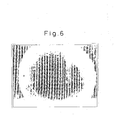
- 238000000635 electron micrograph Methods 0.000 description 2
- 239000003974 emollient agent Substances 0.000 description 2
- 229960003720 enoxolone Drugs 0.000 description 2
- 125000001301 ethoxy group Chemical group [H]C([H])([H])C([H])([H])O* 0.000 description 2
- MTZQAGJQAFMTAQ-UHFFFAOYSA-N ethyl benzoate Chemical compound CCOC(=O)C1=CC=CC=C1 MTZQAGJQAFMTAQ-UHFFFAOYSA-N 0.000 description 2
- MVLVMROFTAUDAG-UHFFFAOYSA-N ethyl octadecanoate Chemical compound CCCCCCCCCCCCCCCCCC(=O)OCC MVLVMROFTAUDAG-UHFFFAOYSA-N 0.000 description 2
- 239000003925 fat Substances 0.000 description 2
- 239000012467 final product Substances 0.000 description 2
- 239000010419 fine particle Substances 0.000 description 2
- 239000011737 fluorine Substances 0.000 description 2
- 229910052731 fluorine Inorganic materials 0.000 description 2
- HYBBIBNJHNGZAN-UHFFFAOYSA-N furfural Chemical compound O=CC1=CC=CO1 HYBBIBNJHNGZAN-UHFFFAOYSA-N 0.000 description 2
- 239000011521 glass Substances 0.000 description 2
- ZEMPKEQAKRGZGQ-XOQCFJPHSA-N glycerol triricinoleate Natural products CCCCCC[C@@H](O)CC=CCCCCCCCC(=O)OC[C@@H](COC(=O)CCCCCCCC=CC[C@@H](O)CCCCCC)OC(=O)CCCCCCCC=CC[C@H](O)CCCCCC ZEMPKEQAKRGZGQ-XOQCFJPHSA-N 0.000 description 2
- 238000010438 heat treatment Methods 0.000 description 2
- IPCSVZSSVZVIGE-UHFFFAOYSA-N hexadecanoic acid Chemical compound CCCCCCCCCCCCCCCC(O)=O IPCSVZSSVZVIGE-UHFFFAOYSA-N 0.000 description 2
- 239000003906 humectant Substances 0.000 description 2
- 229930195733 hydrocarbon Natural products 0.000 description 2
- 150000002430 hydrocarbons Chemical class 0.000 description 2
- 125000001165 hydrophobic group Chemical group 0.000 description 2
- BJRNKVDFDLYUGJ-RMPHRYRLSA-N hydroquinone O-beta-D-glucopyranoside Chemical compound O[C@@H]1[C@@H](O)[C@H](O)[C@@H](CO)O[C@H]1OC1=CC=C(O)C=C1 BJRNKVDFDLYUGJ-RMPHRYRLSA-N 0.000 description 2
- 229910010272 inorganic material Inorganic materials 0.000 description 2
- 239000011147 inorganic material Substances 0.000 description 2
- 229940119170 jojoba wax Drugs 0.000 description 2
- JVTAAEKCZFNVCJ-UHFFFAOYSA-N lactic acid Chemical compound CC(O)C(O)=O JVTAAEKCZFNVCJ-UHFFFAOYSA-N 0.000 description 2
- 239000010985 leather Substances 0.000 description 2
- 239000011777 magnesium Substances 0.000 description 2
- 239000011159 matrix material Substances 0.000 description 2
- 229910044991 metal oxide Inorganic materials 0.000 description 2
- 150000004706 metal oxides Chemical class 0.000 description 2
- 125000000956 methoxy group Chemical group [H]C([H])([H])O* 0.000 description 2
- 238000000465 moulding Methods 0.000 description 2
- GLDOVTGHNKAZLK-UHFFFAOYSA-N octadecan-1-ol Chemical compound CCCCCCCCCCCCCCCCCCO GLDOVTGHNKAZLK-UHFFFAOYSA-N 0.000 description 2
- 239000011368 organic material Substances 0.000 description 2
- 239000005011 phenolic resin Substances 0.000 description 2
- 229920001568 phenolic resin Polymers 0.000 description 2
- ZQBAKBUEJOMQEX-UHFFFAOYSA-N phenyl salicylate Chemical compound OC1=CC=CC=C1C(=O)OC1=CC=CC=C1 ZQBAKBUEJOMQEX-UHFFFAOYSA-N 0.000 description 2
- 229920003023 plastic Polymers 0.000 description 2
- 239000004033 plastic Substances 0.000 description 2
- 229920000728 polyester Polymers 0.000 description 2
- 239000002861 polymer material Substances 0.000 description 2
- 229920002451 polyvinyl alcohol Polymers 0.000 description 2
- 239000004800 polyvinyl chloride Substances 0.000 description 2
- 229920000915 polyvinyl chloride Polymers 0.000 description 2
- 239000005033 polyvinylidene chloride Substances 0.000 description 2
- 229920002981 polyvinylidene fluoride Polymers 0.000 description 2
- 239000003755 preservative agent Substances 0.000 description 2
- 239000011342 resin composition Substances 0.000 description 2
- 238000005096 rolling process Methods 0.000 description 2
- 150000003839 salts Chemical class 0.000 description 2
- 125000005372 silanol group Chemical group 0.000 description 2
- 229920002050 silicone resin Polymers 0.000 description 2
- 239000002002 slurry Substances 0.000 description 2
- 239000000600 sorbitol Substances 0.000 description 2
- 241000894007 species Species 0.000 description 2
- 239000012798 spherical particle Substances 0.000 description 2
- 239000008107 starch Substances 0.000 description 2
- 235000019698 starch Nutrition 0.000 description 2
- 235000000346 sugar Nutrition 0.000 description 2
- 229920006305 unsaturated polyester Polymers 0.000 description 2
- 229930003231 vitamin Natural products 0.000 description 2
- 235000013343 vitamin Nutrition 0.000 description 2
- 239000011782 vitamin Substances 0.000 description 2
- 229940088594 vitamin Drugs 0.000 description 2
- 150000003722 vitamin derivatives Chemical class 0.000 description 2
- XLYOFNOQVPJJNP-UHFFFAOYSA-N water Substances O XLYOFNOQVPJJNP-UHFFFAOYSA-N 0.000 description 2
- OERNJTNJEZOPIA-UHFFFAOYSA-N zirconium nitrate Chemical compound [Zr+4].[O-][N+]([O-])=O.[O-][N+]([O-])=O.[O-][N+]([O-])=O.[O-][N+]([O-])=O OERNJTNJEZOPIA-UHFFFAOYSA-N 0.000 description 2
- HDTRYLNUVZCQOY-UHFFFAOYSA-N α-D-glucopyranosyl-α-D-glucopyranoside Natural products OC1C(O)C(O)C(CO)OC1OC1C(O)C(O)C(O)C(CO)O1 HDTRYLNUVZCQOY-UHFFFAOYSA-N 0.000 description 1
- DEQUKPCANKRTPZ-UHFFFAOYSA-N (2,3-dihydroxyphenyl)-phenylmethanone Chemical compound OC1=CC=CC(C(=O)C=2C=CC=CC=2)=C1O DEQUKPCANKRTPZ-UHFFFAOYSA-N 0.000 description 1
- KIUKXJAPPMFGSW-DNGZLQJQSA-N (2S,3S,4S,5R,6R)-6-[(2S,3R,4R,5S,6R)-3-Acetamido-2-[(2S,3S,4R,5R,6R)-6-[(2R,3R,4R,5S,6R)-3-acetamido-2,5-dihydroxy-6-(hydroxymethyl)oxan-4-yl]oxy-2-carboxy-4,5-dihydroxyoxan-3-yl]oxy-5-hydroxy-6-(hydroxymethyl)oxan-4-yl]oxy-3,4,5-trihydroxyoxane-2-carboxylic acid Chemical compound CC(=O)N[C@H]1[C@H](O)O[C@H](CO)[C@@H](O)[C@@H]1O[C@H]1[C@H](O)[C@@H](O)[C@H](O[C@H]2[C@@H]([C@@H](O[C@H]3[C@@H]([C@@H](O)[C@H](O)[C@H](O3)C(O)=O)O)[C@H](O)[C@@H](CO)O2)NC(C)=O)[C@@H](C(O)=O)O1 KIUKXJAPPMFGSW-DNGZLQJQSA-N 0.000 description 1
- WRIDQFICGBMAFQ-UHFFFAOYSA-N (E)-8-Octadecenoic acid Natural products CCCCCCCCCC=CCCCCCCC(O)=O WRIDQFICGBMAFQ-UHFFFAOYSA-N 0.000 description 1
- 229940058015 1,3-butylene glycol Drugs 0.000 description 1
- VBICKXHEKHSIBG-UHFFFAOYSA-N 1-monostearoylglycerol Chemical compound CCCCCCCCCCCCCCCCCC(=O)OCC(O)CO VBICKXHEKHSIBG-UHFFFAOYSA-N 0.000 description 1
- FPIPGXGPPPQFEQ-UHFFFAOYSA-N 13-cis retinol Natural products OCC=C(C)C=CC=C(C)C=CC1=C(C)CCCC1(C)C FPIPGXGPPPQFEQ-UHFFFAOYSA-N 0.000 description 1
- SPSPIUSUWPLVKD-UHFFFAOYSA-N 2,3-dibutyl-6-methylphenol Chemical compound CCCCC1=CC=C(C)C(O)=C1CCCC SPSPIUSUWPLVKD-UHFFFAOYSA-N 0.000 description 1
- QTWJRLJHJPIABL-UHFFFAOYSA-N 2-methylphenol;3-methylphenol;4-methylphenol Chemical compound CC1=CC=C(O)C=C1.CC1=CC=CC(O)=C1.CC1=CC=CC=C1O QTWJRLJHJPIABL-UHFFFAOYSA-N 0.000 description 1
- LQJBNNIYVWPHFW-UHFFFAOYSA-N 20:1omega9c fatty acid Natural products CCCCCCCCCCC=CCCCCCCCC(O)=O LQJBNNIYVWPHFW-UHFFFAOYSA-N 0.000 description 1
- CYDQOEWLBCCFJZ-UHFFFAOYSA-N 4-(4-fluorophenyl)oxane-4-carboxylic acid Chemical compound C=1C=C(F)C=CC=1C1(C(=O)O)CCOCC1 CYDQOEWLBCCFJZ-UHFFFAOYSA-N 0.000 description 1
- IJALWSVNUBBQRA-UHFFFAOYSA-N 4-Isopropyl-3-methylphenol Chemical compound CC(C)C1=CC=C(O)C=C1C IJALWSVNUBBQRA-UHFFFAOYSA-N 0.000 description 1
- VXEGSRKPIUDPQT-UHFFFAOYSA-N 4-[4-(4-methoxyphenyl)piperazin-1-yl]aniline Chemical compound C1=CC(OC)=CC=C1N1CCN(C=2C=CC(N)=CC=2)CC1 VXEGSRKPIUDPQT-UHFFFAOYSA-N 0.000 description 1
- FJKROLUGYXJWQN-UHFFFAOYSA-N 4-hydroxybenzoic acid Chemical compound OC(=O)C1=CC=C(O)C=C1 FJKROLUGYXJWQN-UHFFFAOYSA-N 0.000 description 1
- DUFCMRCMPHIFTR-UHFFFAOYSA-N 5-(dimethylsulfamoyl)-2-methylfuran-3-carboxylic acid Chemical compound CN(C)S(=O)(=O)C1=CC(C(O)=O)=C(C)O1 DUFCMRCMPHIFTR-UHFFFAOYSA-N 0.000 description 1
- QSBYPNXLFMSGKH-UHFFFAOYSA-N 9-Heptadecensaeure Natural products CCCCCCCC=CCCCCCCCC(O)=O QSBYPNXLFMSGKH-UHFFFAOYSA-N 0.000 description 1
- HRPVXLWXLXDGHG-UHFFFAOYSA-N Acrylamide Chemical compound NC(=O)C=C HRPVXLWXLXDGHG-UHFFFAOYSA-N 0.000 description 1
- 239000004925 Acrylic resin Substances 0.000 description 1
- 229920000178 Acrylic resin Polymers 0.000 description 1
- POJWUDADGALRAB-PVQJCKRUSA-N Allantoin Natural products NC(=O)N[C@@H]1NC(=O)NC1=O POJWUDADGALRAB-PVQJCKRUSA-N 0.000 description 1
- 235000019489 Almond oil Nutrition 0.000 description 1
- 239000005995 Aluminium silicate Substances 0.000 description 1
- 235000021357 Behenic acid Nutrition 0.000 description 1
- 239000005711 Benzoic acid Substances 0.000 description 1
- WRAGBEWQGHCDDU-UHFFFAOYSA-M C([O-])([O-])=O.[NH4+].[Zr+] Chemical compound C([O-])([O-])=O.[NH4+].[Zr+] WRAGBEWQGHCDDU-UHFFFAOYSA-M 0.000 description 1
- 239000004215 Carbon black (E152) Substances 0.000 description 1
- 102000008186 Collagen Human genes 0.000 description 1
- 108010035532 Collagen Proteins 0.000 description 1
- ZZZCUOFIHGPKAK-UHFFFAOYSA-N D-erythro-ascorbic acid Natural products OCC1OC(=O)C(O)=C1O ZZZCUOFIHGPKAK-UHFFFAOYSA-N 0.000 description 1
- RGHNJXZEOKUKBD-UHFFFAOYSA-N D-gluconic acid Natural products OCC(O)C(O)C(O)C(O)C(O)=O RGHNJXZEOKUKBD-UHFFFAOYSA-N 0.000 description 1
- FEWJPZIEWOKRBE-JCYAYHJZSA-N Dextrotartaric acid Chemical compound OC(=O)[C@H](O)[C@@H](O)C(O)=O FEWJPZIEWOKRBE-JCYAYHJZSA-N 0.000 description 1
- KCXVZYZYPLLWCC-UHFFFAOYSA-N EDTA Chemical compound OC(=O)CN(CC(O)=O)CCN(CC(O)=O)CC(O)=O KCXVZYZYPLLWCC-UHFFFAOYSA-N 0.000 description 1
- LVGKNOAMLMIIKO-UHFFFAOYSA-N Elaidinsaeure-aethylester Natural products CCCCCCCCC=CCCCCCCCC(=O)OCC LVGKNOAMLMIIKO-UHFFFAOYSA-N 0.000 description 1
- AFSDNFLWKVMVRB-UHFFFAOYSA-N Ellagic acid Chemical compound OC1=C(O)C(OC2=O)=C3C4=C2C=C(O)C(O)=C4OC(=O)C3=C1 AFSDNFLWKVMVRB-UHFFFAOYSA-N 0.000 description 1
- ATJXMQHAMYVHRX-CPCISQLKSA-N Ellagic acid Natural products OC1=C(O)[C@H]2OC(=O)c3cc(O)c(O)c4OC(=O)C(=C1)[C@H]2c34 ATJXMQHAMYVHRX-CPCISQLKSA-N 0.000 description 1
- 229920002079 Ellagic acid Polymers 0.000 description 1
- 239000004471 Glycine Substances 0.000 description 1
- IMQLKJBTEOYOSI-GPIVLXJGSA-N Inositol-hexakisphosphate Chemical compound OP(O)(=O)O[C@H]1[C@H](OP(O)(O)=O)[C@@H](OP(O)(O)=O)[C@H](OP(O)(O)=O)[C@H](OP(O)(O)=O)[C@@H]1OP(O)(O)=O IMQLKJBTEOYOSI-GPIVLXJGSA-N 0.000 description 1
- QNAYBMKLOCPYGJ-REOHCLBHSA-N L-alanine Chemical compound C[C@H](N)C(O)=O QNAYBMKLOCPYGJ-REOHCLBHSA-N 0.000 description 1
- 150000000996 L-ascorbic acids Chemical class 0.000 description 1
- 239000004166 Lanolin Substances 0.000 description 1
- 239000005639 Lauric acid Substances 0.000 description 1
- 235000018330 Macadamia integrifolia Nutrition 0.000 description 1
- 240000000912 Macadamia tetraphylla Species 0.000 description 1
- 235000003800 Macadamia tetraphylla Nutrition 0.000 description 1
- 239000004594 Masterbatch (MB) Substances 0.000 description 1
- 239000004677 Nylon Substances 0.000 description 1
- 229920002292 Nylon 6 Polymers 0.000 description 1
- 229920002302 Nylon 6,6 Polymers 0.000 description 1
- MXRIRQGCELJRSN-UHFFFAOYSA-N O.O.O.[Al] Chemical compound O.O.O.[Al] MXRIRQGCELJRSN-UHFFFAOYSA-N 0.000 description 1
- YBGZDTIWKVFICR-JLHYYAGUSA-N Octyl 4-methoxycinnamic acid Chemical compound CCCCC(CC)COC(=O)\C=C\C1=CC=C(OC)C=C1 YBGZDTIWKVFICR-JLHYYAGUSA-N 0.000 description 1
- 239000005642 Oleic acid Substances 0.000 description 1
- ZQPPMHVWECSIRJ-UHFFFAOYSA-N Oleic acid Natural products CCCCCCCCC=CCCCCCCCC(O)=O ZQPPMHVWECSIRJ-UHFFFAOYSA-N 0.000 description 1
- 229910019142 PO4 Inorganic materials 0.000 description 1
- 235000021314 Palmitic acid Nutrition 0.000 description 1
- IMQLKJBTEOYOSI-UHFFFAOYSA-N Phytic acid Natural products OP(O)(=O)OC1C(OP(O)(O)=O)C(OP(O)(O)=O)C(OP(O)(O)=O)C(OP(O)(O)=O)C1OP(O)(O)=O IMQLKJBTEOYOSI-UHFFFAOYSA-N 0.000 description 1
- 239000004952 Polyamide Substances 0.000 description 1
- 239000004698 Polyethylene Substances 0.000 description 1
- 239000004743 Polypropylene Substances 0.000 description 1
- 229920001214 Polysorbate 60 Polymers 0.000 description 1
- 239000004793 Polystyrene Substances 0.000 description 1
- 235000019484 Rapeseed oil Nutrition 0.000 description 1
- 229920000297 Rayon Polymers 0.000 description 1
- 235000019485 Safflower oil Nutrition 0.000 description 1
- DWAQJAXMDSEUJJ-UHFFFAOYSA-M Sodium bisulfite Chemical compound [Na+].OS([O-])=O DWAQJAXMDSEUJJ-UHFFFAOYSA-M 0.000 description 1
- 235000021355 Stearic acid Nutrition 0.000 description 1
- 235000019486 Sunflower oil Nutrition 0.000 description 1
- FEWJPZIEWOKRBE-UHFFFAOYSA-N Tartaric acid Natural products [H+].[H+].[O-]C(=O)C(O)C(O)C([O-])=O FEWJPZIEWOKRBE-UHFFFAOYSA-N 0.000 description 1
- 244000299461 Theobroma cacao Species 0.000 description 1
- 235000005764 Theobroma cacao ssp. cacao Nutrition 0.000 description 1
- 235000005767 Theobroma cacao ssp. sphaerocarpum Nutrition 0.000 description 1
- 229910003082 TiO2-SiO2 Inorganic materials 0.000 description 1
- HDTRYLNUVZCQOY-WSWWMNSNSA-N Trehalose Natural products O[C@@H]1[C@@H](O)[C@@H](O)[C@@H](CO)O[C@@H]1O[C@@H]1[C@H](O)[C@@H](O)[C@@H](O)[C@@H](CO)O1 HDTRYLNUVZCQOY-WSWWMNSNSA-N 0.000 description 1
- WGLPBDUCMAPZCE-UHFFFAOYSA-N Trioxochromium Chemical compound O=[Cr](=O)=O WGLPBDUCMAPZCE-UHFFFAOYSA-N 0.000 description 1
- FPIPGXGPPPQFEQ-BOOMUCAASA-N Vitamin A Natural products OC/C=C(/C)\C=C\C=C(\C)/C=C/C1=C(C)CCCC1(C)C FPIPGXGPPPQFEQ-BOOMUCAASA-N 0.000 description 1
- 229930003268 Vitamin C Natural products 0.000 description 1
- 229930003427 Vitamin E Natural products 0.000 description 1
- YRXGUZPUZBCGST-UHFFFAOYSA-N [2-(hydroxymethoxy)phenyl]-phenylmethanone Chemical compound OCOC1=CC=CC=C1C(=O)C1=CC=CC=C1 YRXGUZPUZBCGST-UHFFFAOYSA-N 0.000 description 1
- 239000006096 absorbing agent Substances 0.000 description 1
- 229920000122 acrylonitrile butadiene styrene Polymers 0.000 description 1
- 230000002411 adverse Effects 0.000 description 1
- 239000012773 agricultural material Substances 0.000 description 1
- 235000004279 alanine Nutrition 0.000 description 1
- 150000001298 alcohols Chemical class 0.000 description 1
- 229920000180 alkyd Polymers 0.000 description 1
- 150000005215 alkyl ethers Chemical class 0.000 description 1
- FPIPGXGPPPQFEQ-OVSJKPMPSA-N all-trans-retinol Chemical compound OC\C=C(/C)\C=C\C=C(/C)\C=C\C1=C(C)CCCC1(C)C FPIPGXGPPPQFEQ-OVSJKPMPSA-N 0.000 description 1
- 229960000458 allantoin Drugs 0.000 description 1
- 239000000956 alloy Substances 0.000 description 1
- 229910045601 alloy Inorganic materials 0.000 description 1
- 239000008168 almond oil Substances 0.000 description 1
- HDTRYLNUVZCQOY-LIZSDCNHSA-N alpha,alpha-trehalose Chemical compound O[C@@H]1[C@@H](O)[C@H](O)[C@@H](CO)O[C@@H]1O[C@@H]1[C@H](O)[C@@H](O)[C@H](O)[C@@H](CO)O1 HDTRYLNUVZCQOY-LIZSDCNHSA-N 0.000 description 1
- TUFYVOCKVJOUIR-UHFFFAOYSA-N alpha-Thujaplicin Natural products CC(C)C=1C=CC=CC(=O)C=1O TUFYVOCKVJOUIR-UHFFFAOYSA-N 0.000 description 1
- XAGFODPZIPBFFR-UHFFFAOYSA-N aluminium Chemical compound [Al] XAGFODPZIPBFFR-UHFFFAOYSA-N 0.000 description 1
- 235000012211 aluminium silicate Nutrition 0.000 description 1
- 239000003945 anionic surfactant Substances 0.000 description 1
- 239000003242 anti bacterial agent Substances 0.000 description 1
- 230000003712 anti-aging effect Effects 0.000 description 1
- 230000000844 anti-bacterial effect Effects 0.000 description 1
- 239000002216 antistatic agent Substances 0.000 description 1
- 239000008346 aqueous phase Substances 0.000 description 1
- 239000004760 aramid Substances 0.000 description 1
- 229960000271 arbutin Drugs 0.000 description 1
- 229920003235 aromatic polyamide Polymers 0.000 description 1
- 235000010323 ascorbic acid Nutrition 0.000 description 1
- 239000011668 ascorbic acid Substances 0.000 description 1
- 229960005070 ascorbic acid Drugs 0.000 description 1
- 239000012298 atmosphere Substances 0.000 description 1
- 235000021302 avocado oil Nutrition 0.000 description 1
- 239000008163 avocado oil Substances 0.000 description 1
- IRERQBUNZFJFGC-UHFFFAOYSA-L azure blue Chemical compound [Na+].[Na+].[Na+].[Na+].[Na+].[Na+].[Na+].[Na+].[Al+3].[Al+3].[Al+3].[Al+3].[Al+3].[Al+3].[S-]S[S-].[O-][Si]([O-])([O-])[O-].[O-][Si]([O-])([O-])[O-].[O-][Si]([O-])([O-])[O-].[O-][Si]([O-])([O-])[O-].[O-][Si]([O-])([O-])[O-].[O-][Si]([O-])([O-])[O-] IRERQBUNZFJFGC-UHFFFAOYSA-L 0.000 description 1
- 239000003899 bactericide agent Substances 0.000 description 1
- 235000013871 bee wax Nutrition 0.000 description 1
- 235000015278 beef Nutrition 0.000 description 1
- 239000012166 beeswax Substances 0.000 description 1
- 229940092738 beeswax Drugs 0.000 description 1
- 229940116226 behenic acid Drugs 0.000 description 1
- BLFLLBZGZJTVJG-UHFFFAOYSA-N benzocaine Chemical compound CCOC(=O)C1=CC=C(N)C=C1 BLFLLBZGZJTVJG-UHFFFAOYSA-N 0.000 description 1
- 235000010233 benzoic acid Nutrition 0.000 description 1
- 239000001518 benzyl (E)-3-phenylprop-2-enoate Substances 0.000 description 1
- 235000019445 benzyl alcohol Nutrition 0.000 description 1
- NGHOLYJTSCBCGC-QXMHVHEDSA-N benzyl cinnamate Chemical compound C=1C=CC=CC=1\C=C/C(=O)OCC1=CC=CC=C1 NGHOLYJTSCBCGC-QXMHVHEDSA-N 0.000 description 1
- 230000015572 biosynthetic process Effects 0.000 description 1
- 239000007844 bleaching agent Substances 0.000 description 1
- 238000009835 boiling Methods 0.000 description 1
- 239000000872 buffer Substances 0.000 description 1
- 239000004566 building material Substances 0.000 description 1
- 235000019437 butane-1,3-diol Nutrition 0.000 description 1
- DHAZIUXMHRHVMP-UHFFFAOYSA-N butyl tetradecanoate Chemical compound CCCCCCCCCCCCCC(=O)OCCCC DHAZIUXMHRHVMP-UHFFFAOYSA-N 0.000 description 1
- CZBZUDVBLSSABA-UHFFFAOYSA-N butylated hydroxyanisole Chemical compound COC1=CC=C(O)C(C(C)(C)C)=C1.COC1=CC=C(O)C=C1C(C)(C)C CZBZUDVBLSSABA-UHFFFAOYSA-N 0.000 description 1
- 235000010354 butylated hydroxytoluene Nutrition 0.000 description 1
- 235000001046 cacaotero Nutrition 0.000 description 1
- 229910000019 calcium carbonate Inorganic materials 0.000 description 1
- 235000010216 calcium carbonate Nutrition 0.000 description 1
- BRPQOXSCLDDYGP-UHFFFAOYSA-N calcium oxide Chemical compound [O-2].[Ca+2] BRPQOXSCLDDYGP-UHFFFAOYSA-N 0.000 description 1
- 239000000292 calcium oxide Substances 0.000 description 1
- ODINCKMPIJJUCX-UHFFFAOYSA-N calcium oxide Inorganic materials [Ca]=O ODINCKMPIJJUCX-UHFFFAOYSA-N 0.000 description 1
- 229940106189 ceramide Drugs 0.000 description 1
- 150000001783 ceramides Chemical class 0.000 description 1
- 229910000420 cerium oxide Inorganic materials 0.000 description 1
- 229960000541 cetyl alcohol Drugs 0.000 description 1
- 229940119217 chamomile extract Drugs 0.000 description 1
- 235000020221 chamomile extract Nutrition 0.000 description 1
- 230000008859 change Effects 0.000 description 1
- 229910000423 chromium oxide Inorganic materials 0.000 description 1
- CMDKPGRTAQVGFQ-RMKNXTFCSA-N cinoxate Chemical compound CCOCCOC(=O)\C=C\C1=CC=C(OC)C=C1 CMDKPGRTAQVGFQ-RMKNXTFCSA-N 0.000 description 1
- 229960001063 cinoxate Drugs 0.000 description 1
- NGHOLYJTSCBCGC-UHFFFAOYSA-N cis-cinnamic acid benzyl ester Natural products C=1C=CC=CC=1C=CC(=O)OCC1=CC=CC=C1 NGHOLYJTSCBCGC-UHFFFAOYSA-N 0.000 description 1
- 235000015165 citric acid Nutrition 0.000 description 1
- 239000008199 coating composition Substances 0.000 description 1
- 229920001436 collagen Polymers 0.000 description 1
- 150000001875 compounds Chemical class 0.000 description 1
- 239000004567 concrete Substances 0.000 description 1
- 239000004020 conductor Substances 0.000 description 1
- 238000007796 conventional method Methods 0.000 description 1
- 239000007771 core particle Substances 0.000 description 1
- 229930003836 cresol Natural products 0.000 description 1
- 238000000354 decomposition reaction Methods 0.000 description 1
- 238000004925 denaturation Methods 0.000 description 1
- 230000036425 denaturation Effects 0.000 description 1
- IJKVHSBPTUYDLN-UHFFFAOYSA-N dihydroxy(oxo)silane Chemical compound O[Si](O)=O IJKVHSBPTUYDLN-UHFFFAOYSA-N 0.000 description 1
- 239000004205 dimethyl polysiloxane Substances 0.000 description 1
- 235000013870 dimethyl polysiloxane Nutrition 0.000 description 1
- 229910001873 dinitrogen Inorganic materials 0.000 description 1
- SZXQTJUDPRGNJN-UHFFFAOYSA-N dipropylene glycol Chemical compound OCCCOCCCO SZXQTJUDPRGNJN-UHFFFAOYSA-N 0.000 description 1
- 150000002016 disaccharides Chemical class 0.000 description 1
- 229960000735 docosanol Drugs 0.000 description 1
- 229920001971 elastomer Polymers 0.000 description 1
- 229960002852 ellagic acid Drugs 0.000 description 1
- 235000004132 ellagic acid Nutrition 0.000 description 1
- BEFDCLMNVWHSGT-UHFFFAOYSA-N ethenylcyclopentane Chemical compound C=CC1CCCC1 BEFDCLMNVWHSGT-UHFFFAOYSA-N 0.000 description 1
- HPMLGOFBKNGJAM-ONEGZZNKSA-N ethyl (e)-3-(1h-imidazol-5-yl)prop-2-enoate Chemical compound CCOC(=O)\C=C\C1=CN=CN1 HPMLGOFBKNGJAM-ONEGZZNKSA-N 0.000 description 1
- LVGKNOAMLMIIKO-QXMHVHEDSA-N ethyl oleate Chemical compound CCCCCCCC\C=C/CCCCCCCC(=O)OCC LVGKNOAMLMIIKO-QXMHVHEDSA-N 0.000 description 1
- 229940093471 ethyl oleate Drugs 0.000 description 1
- 238000011156 evaluation Methods 0.000 description 1
- 235000008524 evening primrose extract Nutrition 0.000 description 1
- 239000010475 evening primrose oil Substances 0.000 description 1
- 229940089020 evening primrose oil Drugs 0.000 description 1
- 239000000284 extract Substances 0.000 description 1
- 239000004744 fabric Substances 0.000 description 1
- 238000011049 filling Methods 0.000 description 1
- 125000000524 functional group Chemical group 0.000 description 1
- WIGCFUFOHFEKBI-UHFFFAOYSA-N gamma-tocopherol Natural products CC(C)CCCC(C)CCCC(C)CCCC1CCC2C(C)C(O)C(C)C(C)C2O1 WIGCFUFOHFEKBI-UHFFFAOYSA-N 0.000 description 1
- 239000000174 gluconic acid Substances 0.000 description 1
- 235000012208 gluconic acid Nutrition 0.000 description 1
- 235000011187 glycerol Nutrition 0.000 description 1
- 229930182470 glycoside Natural products 0.000 description 1
- BXWNKGSJHAJOGX-UHFFFAOYSA-N hexadecan-1-ol Chemical compound CCCCCCCCCCCCCCCCO BXWNKGSJHAJOGX-UHFFFAOYSA-N 0.000 description 1
- 229920002674 hyaluronan Polymers 0.000 description 1
- 229960003160 hyaluronic acid Drugs 0.000 description 1
- 238000009396 hybridization Methods 0.000 description 1
- 230000007062 hydrolysis Effects 0.000 description 1
- 238000006460 hydrolysis reaction Methods 0.000 description 1
- FMXLGOWFNZLJQK-UHFFFAOYSA-N hypochlorous acid;zirconium Chemical compound [Zr].ClO FMXLGOWFNZLJQK-UHFFFAOYSA-N 0.000 description 1
- 150000003949 imides Chemical class 0.000 description 1
- 239000011810 insulating material Substances 0.000 description 1
- WTFXARWRTYJXII-UHFFFAOYSA-N iron(2+);iron(3+);oxygen(2-) Chemical compound [O-2].[O-2].[O-2].[O-2].[Fe+2].[Fe+3].[Fe+3] WTFXARWRTYJXII-UHFFFAOYSA-N 0.000 description 1
- SZVJSHCCFOBDDC-UHFFFAOYSA-N iron(II,III) oxide Inorganic materials O=[Fe]O[Fe]O[Fe]=O SZVJSHCCFOBDDC-UHFFFAOYSA-N 0.000 description 1
- JEIPFZHSYJVQDO-UHFFFAOYSA-N iron(III) oxide Inorganic materials O=[Fe]O[Fe]=O JEIPFZHSYJVQDO-UHFFFAOYSA-N 0.000 description 1
- QXJSBBXBKPUZAA-UHFFFAOYSA-N isooleic acid Natural products CCCCCCCC=CCCCCCCCCC(O)=O QXJSBBXBKPUZAA-UHFFFAOYSA-N 0.000 description 1
- NFIDBGJMFKNGGQ-UHFFFAOYSA-N isopropylmethylphenol Natural products CC(C)CC1=CC=CC=C1O NFIDBGJMFKNGGQ-UHFFFAOYSA-N 0.000 description 1
- NLYAJNPCOHFWQQ-UHFFFAOYSA-N kaolin Chemical compound O.O.O=[Al]O[Si](=O)O[Si](=O)O[Al]=O NLYAJNPCOHFWQQ-UHFFFAOYSA-N 0.000 description 1
- BEJNERDRQOWKJM-UHFFFAOYSA-N kojic acid Chemical compound OCC1=CC(=O)C(O)=CO1 BEJNERDRQOWKJM-UHFFFAOYSA-N 0.000 description 1
- 229960004705 kojic acid Drugs 0.000 description 1
- WZNJWVWKTVETCG-UHFFFAOYSA-N kojic acid Natural products OC(=O)C(N)CN1C=CC(=O)C(O)=C1 WZNJWVWKTVETCG-UHFFFAOYSA-N 0.000 description 1
- 239000004310 lactic acid Substances 0.000 description 1
- 235000014655 lactic acid Nutrition 0.000 description 1
- 235000019388 lanolin Nutrition 0.000 description 1
- 229940039717 lanolin Drugs 0.000 description 1
- 229940057995 liquid paraffin Drugs 0.000 description 1
- 229940074358 magnesium ascorbate Drugs 0.000 description 1
- ZLNQQNXFFQJAID-UHFFFAOYSA-L magnesium carbonate Chemical compound [Mg+2].[O-]C([O-])=O ZLNQQNXFFQJAID-UHFFFAOYSA-L 0.000 description 1
- 239000001095 magnesium carbonate Substances 0.000 description 1
- 229910000021 magnesium carbonate Inorganic materials 0.000 description 1
- 239000000395 magnesium oxide Substances 0.000 description 1
- CPLXHLVBOLITMK-UHFFFAOYSA-N magnesium oxide Inorganic materials [Mg]=O CPLXHLVBOLITMK-UHFFFAOYSA-N 0.000 description 1
- AIOKQVJVNPDJKA-ZZMNMWMASA-L magnesium;(2r)-2-[(1s)-1,2-dihydroxyethyl]-4-hydroxy-5-oxo-2h-furan-3-olate Chemical compound [Mg+2].OC[C@H](O)[C@H]1OC(=O)C(O)=C1[O-].OC[C@H](O)[C@H]1OC(=O)C(O)=C1[O-] AIOKQVJVNPDJKA-ZZMNMWMASA-L 0.000 description 1
- AXZKOIWUVFPNLO-UHFFFAOYSA-N magnesium;oxygen(2-) Chemical compound [O-2].[Mg+2] AXZKOIWUVFPNLO-UHFFFAOYSA-N 0.000 description 1
- 229910001507 metal halide Inorganic materials 0.000 description 1
- 150000005309 metal halides Chemical class 0.000 description 1
- 150000002739 metals Chemical class 0.000 description 1
- FAARLWTXUUQFSN-UHFFFAOYSA-N methylellagic acid Natural products O1C(=O)C2=CC(O)=C(O)C3=C2C2=C1C(OC)=C(O)C=C2C(=O)O3 FAARLWTXUUQFSN-UHFFFAOYSA-N 0.000 description 1
- 239000010445 mica Substances 0.000 description 1
- 229910052618 mica group Inorganic materials 0.000 description 1
- 238000003801 milling Methods 0.000 description 1
- 239000003607 modifier Substances 0.000 description 1
- WQEPLUUGTLDZJY-UHFFFAOYSA-N n-Pentadecanoic acid Natural products CCCCCCCCCCCCCCC(O)=O WQEPLUUGTLDZJY-UHFFFAOYSA-N 0.000 description 1
- JXTPJDDICSTXJX-UHFFFAOYSA-N n-Triacontane Natural products CCCCCCCCCCCCCCCCCCCCCCCCCCCCCC JXTPJDDICSTXJX-UHFFFAOYSA-N 0.000 description 1
- GOQYKNQRPGWPLP-UHFFFAOYSA-N n-heptadecyl alcohol Natural products CCCCCCCCCCCCCCCCCO GOQYKNQRPGWPLP-UHFFFAOYSA-N 0.000 description 1
- 239000000025 natural resin Substances 0.000 description 1
- 239000002736 nonionic surfactant Substances 0.000 description 1
- 239000010466 nut oil Substances 0.000 description 1
- 229920001778 nylon Polymers 0.000 description 1
- QIQXTHQIDYTFRH-UHFFFAOYSA-N octadecanoic acid Chemical compound CCCCCCCCCCCCCCCCCC(O)=O QIQXTHQIDYTFRH-UHFFFAOYSA-N 0.000 description 1
- OQCDKBAXFALNLD-UHFFFAOYSA-N octadecanoic acid Natural products CCCCCCCC(C)CCCCCCCCC(O)=O OQCDKBAXFALNLD-UHFFFAOYSA-N 0.000 description 1
- 229960001679 octinoxate Drugs 0.000 description 1
- 125000002347 octyl group Chemical group [H]C([*])([H])C([H])([H])C([H])([H])C([H])([H])C([H])([H])C([H])([H])C([H])([H])C([H])([H])[H] 0.000 description 1
- ZQPPMHVWECSIRJ-KTKRTIGZSA-N oleic acid Chemical compound CCCCCCCC\C=C/CCCCCCCC(O)=O ZQPPMHVWECSIRJ-KTKRTIGZSA-N 0.000 description 1
- 239000004006 olive oil Substances 0.000 description 1
- 235000008390 olive oil Nutrition 0.000 description 1
- 150000007524 organic acids Chemical class 0.000 description 1
- 239000003960 organic solvent Substances 0.000 description 1
- 230000003647 oxidation Effects 0.000 description 1
- 238000007254 oxidation reaction Methods 0.000 description 1
- BMMGVYCKOGBVEV-UHFFFAOYSA-N oxo(oxoceriooxy)cerium Chemical compound [Ce]=O.O=[Ce]=O BMMGVYCKOGBVEV-UHFFFAOYSA-N 0.000 description 1
- CMOAHYOGLLEOGO-UHFFFAOYSA-N oxozirconium;dihydrochloride Chemical compound Cl.Cl.[Zr]=O CMOAHYOGLLEOGO-UHFFFAOYSA-N 0.000 description 1
- BJRNKVDFDLYUGJ-UHFFFAOYSA-N p-hydroxyphenyl beta-D-alloside Natural products OC1C(O)C(O)C(CO)OC1OC1=CC=C(O)C=C1 BJRNKVDFDLYUGJ-UHFFFAOYSA-N 0.000 description 1
- 239000003973 paint Substances 0.000 description 1
- 229940056211 paraffin Drugs 0.000 description 1
- 239000012188 paraffin wax Substances 0.000 description 1
- WXZMFSXDPGVJKK-UHFFFAOYSA-N pentaerythritol Chemical compound OCC(CO)(CO)CO WXZMFSXDPGVJKK-UHFFFAOYSA-N 0.000 description 1
- WCVRQHFDJLLWFE-UHFFFAOYSA-N pentane-1,2-diol Chemical compound CCCC(O)CO WCVRQHFDJLLWFE-UHFFFAOYSA-N 0.000 description 1
- 239000002304 perfume Substances 0.000 description 1
- 229960000969 phenyl salicylate Drugs 0.000 description 1
- NBIIXXVUZAFLBC-UHFFFAOYSA-K phosphate Chemical compound [O-]P([O-])([O-])=O NBIIXXVUZAFLBC-UHFFFAOYSA-K 0.000 description 1
- 239000010452 phosphate Substances 0.000 description 1
- 235000002949 phytic acid Nutrition 0.000 description 1
- 239000000467 phytic acid Substances 0.000 description 1
- 229940068041 phytic acid Drugs 0.000 description 1
- 239000000049 pigment Substances 0.000 description 1
- 239000000419 plant extract Substances 0.000 description 1
- 229920000435 poly(dimethylsiloxane) Polymers 0.000 description 1
- 229920003229 poly(methyl methacrylate) Polymers 0.000 description 1
- 229920002401 polyacrylamide Polymers 0.000 description 1
- 229920002647 polyamide Polymers 0.000 description 1
- 239000004417 polycarbonate Substances 0.000 description 1
- 229920000515 polycarbonate Polymers 0.000 description 1
- 229920000573 polyethylene Polymers 0.000 description 1
- 229920000139 polyethylene terephthalate Polymers 0.000 description 1
- 239000005020 polyethylene terephthalate Substances 0.000 description 1
- 229920000642 polymer Polymers 0.000 description 1
- 239000004926 polymethyl methacrylate Substances 0.000 description 1
- 229920000098 polyolefin Polymers 0.000 description 1
- 229920001155 polypropylene Polymers 0.000 description 1
- 229920002223 polystyrene Polymers 0.000 description 1
- 238000001556 precipitation Methods 0.000 description 1
- 230000002335 preservative effect Effects 0.000 description 1
- 239000011164 primary particle Substances 0.000 description 1
- 238000007639 printing Methods 0.000 description 1
- TVCBSVKTTHLKQC-UHFFFAOYSA-M propanoate;zirconium(4+) Chemical compound [Zr+4].CCC([O-])=O TVCBSVKTTHLKQC-UHFFFAOYSA-M 0.000 description 1
- 239000002964 rayon Substances 0.000 description 1
- 230000002787 reinforcement Effects 0.000 description 1
- 238000011160 research Methods 0.000 description 1
- 239000005060 rubber Substances 0.000 description 1
- 235000005713 safflower oil Nutrition 0.000 description 1
- 239000003813 safflower oil Substances 0.000 description 1
- 238000010008 shearing Methods 0.000 description 1
- RMAQACBXLXPBSY-UHFFFAOYSA-N silicic acid Chemical compound O[Si](O)(O)O RMAQACBXLXPBSY-UHFFFAOYSA-N 0.000 description 1
- 229910052710 silicon Inorganic materials 0.000 description 1
- 150000003377 silicon compounds Chemical class 0.000 description 1
- 235000012239 silicon dioxide Nutrition 0.000 description 1
- 239000005049 silicon tetrachloride Substances 0.000 description 1
- 229920002545 silicone oil Polymers 0.000 description 1
- 239000000344 soap Substances 0.000 description 1
- 239000001509 sodium citrate Substances 0.000 description 1
- NLJMYIDDQXHKNR-UHFFFAOYSA-K sodium citrate Chemical compound O.O.[Na+].[Na+].[Na+].[O-]C(=O)CC(O)(CC([O-])=O)C([O-])=O NLJMYIDDQXHKNR-UHFFFAOYSA-K 0.000 description 1
- 235000011083 sodium citrates Nutrition 0.000 description 1
- 229940079827 sodium hydrogen sulfite Drugs 0.000 description 1
- 235000010267 sodium hydrogen sulphite Nutrition 0.000 description 1
- 239000001540 sodium lactate Substances 0.000 description 1
- 235000011088 sodium lactate Nutrition 0.000 description 1
- 229940005581 sodium lactate Drugs 0.000 description 1
- 235000019830 sodium polyphosphate Nutrition 0.000 description 1
- XNRNJIIJLOFJEK-UHFFFAOYSA-N sodium;1-oxidopyridine-2-thione Chemical compound [Na+].[O-]N1C=CC=CC1=S XNRNJIIJLOFJEK-UHFFFAOYSA-N 0.000 description 1
- 239000002904 solvent Substances 0.000 description 1
- 235000010199 sorbic acid Nutrition 0.000 description 1
- 239000004334 sorbic acid Substances 0.000 description 1
- 229940075582 sorbic acid Drugs 0.000 description 1
- 229940032094 squalane Drugs 0.000 description 1
- 239000010935 stainless steel Substances 0.000 description 1
- 229910001220 stainless steel Inorganic materials 0.000 description 1
- SFVFIFLLYFPGHH-UHFFFAOYSA-M stearalkonium chloride Chemical compound [Cl-].CCCCCCCCCCCCCCCCCC[N+](C)(C)CC1=CC=CC=C1 SFVFIFLLYFPGHH-UHFFFAOYSA-M 0.000 description 1
- 239000008117 stearic acid Substances 0.000 description 1
- 229940012831 stearyl alcohol Drugs 0.000 description 1
- 238000003756 stirring Methods 0.000 description 1
- 150000005846 sugar alcohols Polymers 0.000 description 1
- 150000008163 sugars Chemical class 0.000 description 1
- 239000002600 sunflower oil Substances 0.000 description 1
- 239000004094 surface-active agent Substances 0.000 description 1
- 239000000454 talc Substances 0.000 description 1
- 229910052623 talc Inorganic materials 0.000 description 1
- 235000012222 talc Nutrition 0.000 description 1
- 239000003760 tallow Substances 0.000 description 1
- 235000002906 tartaric acid Nutrition 0.000 description 1
- 239000011975 tartaric acid Substances 0.000 description 1
- 238000012360 testing method Methods 0.000 description 1
- TUNFSRHWOTWDNC-HKGQFRNVSA-N tetradecanoic acid Chemical compound CCCCCCCCCCCCC[14C](O)=O TUNFSRHWOTWDNC-HKGQFRNVSA-N 0.000 description 1
- 229920005992 thermoplastic resin Polymers 0.000 description 1
- 229920001187 thermosetting polymer Polymers 0.000 description 1
- OGIDPMRJRNCKJF-UHFFFAOYSA-N titanium oxide Inorganic materials [Ti]=O OGIDPMRJRNCKJF-UHFFFAOYSA-N 0.000 description 1
- 230000007704 transition Effects 0.000 description 1
- 150000005691 triesters Chemical class 0.000 description 1
- UFTFJSFQGQCHQW-UHFFFAOYSA-N triformin Chemical compound O=COCC(OC=O)COC=O UFTFJSFQGQCHQW-UHFFFAOYSA-N 0.000 description 1
- 229940099259 vaseline Drugs 0.000 description 1
- 235000015112 vegetable and seed oil Nutrition 0.000 description 1
- 239000008158 vegetable oil Substances 0.000 description 1
- 239000003981 vehicle Substances 0.000 description 1
- 239000004034 viscosity adjusting agent Substances 0.000 description 1
- 235000019155 vitamin A Nutrition 0.000 description 1
- 239000011719 vitamin A Substances 0.000 description 1
- 235000019154 vitamin C Nutrition 0.000 description 1
- 239000011718 vitamin C Substances 0.000 description 1
- 235000019165 vitamin E Nutrition 0.000 description 1
- 229940046009 vitamin E Drugs 0.000 description 1
- 239000011709 vitamin E Substances 0.000 description 1
- 229940045997 vitamin a Drugs 0.000 description 1
- 239000001993 wax Substances 0.000 description 1
- 230000002087 whitening effect Effects 0.000 description 1
- 150000003755 zirconium compounds Chemical class 0.000 description 1
- ZXAUZSQITFJWPS-UHFFFAOYSA-J zirconium(4+);disulfate Chemical compound [Zr+4].[O-]S([O-])(=O)=O.[O-]S([O-])(=O)=O ZXAUZSQITFJWPS-UHFFFAOYSA-J 0.000 description 1
- 239000004711 α-olefin Substances 0.000 description 1
- 229930007845 β-thujaplicin Natural products 0.000 description 1
Images

Classifications
-
- C—CHEMISTRY; METALLURGY
- C09—DYES; PAINTS; POLISHES; NATURAL RESINS; ADHESIVES; COMPOSITIONS NOT OTHERWISE PROVIDED FOR; APPLICATIONS OF MATERIALS NOT OTHERWISE PROVIDED FOR
- C09C—TREATMENT OF INORGANIC MATERIALS, OTHER THAN FIBROUS FILLERS, TO ENHANCE THEIR PIGMENTING OR FILLING PROPERTIES ; PREPARATION OF CARBON BLACK ; PREPARATION OF INORGANIC MATERIALS WHICH ARE NO SINGLE CHEMICAL COMPOUNDS AND WHICH ARE MAINLY USED AS PIGMENTS OR FILLERS
- C09C1/00—Treatment of specific inorganic materials other than fibrous fillers; Preparation of carbon black
- C09C1/36—Compounds of titanium
- C09C1/3607—Titanium dioxide
- C09C1/3653—Treatment with inorganic compounds
- C09C1/3661—Coating
-
- B—PERFORMING OPERATIONS; TRANSPORTING
- B82—NANOTECHNOLOGY
- B82Y—SPECIFIC USES OR APPLICATIONS OF NANOSTRUCTURES; MEASUREMENT OR ANALYSIS OF NANOSTRUCTURES; MANUFACTURE OR TREATMENT OF NANOSTRUCTURES
- B82Y30/00—Nanotechnology for materials or surface science, e.g. nanocomposites
-
- C—CHEMISTRY; METALLURGY
- C09—DYES; PAINTS; POLISHES; NATURAL RESINS; ADHESIVES; COMPOSITIONS NOT OTHERWISE PROVIDED FOR; APPLICATIONS OF MATERIALS NOT OTHERWISE PROVIDED FOR
- C09C—TREATMENT OF INORGANIC MATERIALS, OTHER THAN FIBROUS FILLERS, TO ENHANCE THEIR PIGMENTING OR FILLING PROPERTIES ; PREPARATION OF CARBON BLACK ; PREPARATION OF INORGANIC MATERIALS WHICH ARE NO SINGLE CHEMICAL COMPOUNDS AND WHICH ARE MAINLY USED AS PIGMENTS OR FILLERS
- C09C1/00—Treatment of specific inorganic materials other than fibrous fillers; Preparation of carbon black
- C09C1/40—Compounds of aluminium
- C09C1/407—Aluminium oxides or hydroxides
-
- C—CHEMISTRY; METALLURGY
- C09—DYES; PAINTS; POLISHES; NATURAL RESINS; ADHESIVES; COMPOSITIONS NOT OTHERWISE PROVIDED FOR; APPLICATIONS OF MATERIALS NOT OTHERWISE PROVIDED FOR
- C09C—TREATMENT OF INORGANIC MATERIALS, OTHER THAN FIBROUS FILLERS, TO ENHANCE THEIR PIGMENTING OR FILLING PROPERTIES ; PREPARATION OF CARBON BLACK ; PREPARATION OF INORGANIC MATERIALS WHICH ARE NO SINGLE CHEMICAL COMPOUNDS AND WHICH ARE MAINLY USED AS PIGMENTS OR FILLERS
- C09C3/00—Treatment in general of inorganic materials, other than fibrous fillers, to enhance their pigmenting or filling properties
- C09C3/06—Treatment with inorganic compounds
- C09C3/063—Coating
-
- C—CHEMISTRY; METALLURGY
- C01—INORGANIC CHEMISTRY
- C01P—INDEXING SCHEME RELATING TO STRUCTURAL AND PHYSICAL ASPECTS OF SOLID INORGANIC COMPOUNDS
- C01P2004/00—Particle morphology
- C01P2004/01—Particle morphology depicted by an image
- C01P2004/04—Particle morphology depicted by an image obtained by TEM, STEM, STM or AFM
-
- C—CHEMISTRY; METALLURGY
- C01—INORGANIC CHEMISTRY
- C01P—INDEXING SCHEME RELATING TO STRUCTURAL AND PHYSICAL ASPECTS OF SOLID INORGANIC COMPOUNDS
- C01P2004/00—Particle morphology
- C01P2004/51—Particles with a specific particle size distribution
-
- C—CHEMISTRY; METALLURGY
- C01—INORGANIC CHEMISTRY
- C01P—INDEXING SCHEME RELATING TO STRUCTURAL AND PHYSICAL ASPECTS OF SOLID INORGANIC COMPOUNDS
- C01P2004/00—Particle morphology
- C01P2004/60—Particles characterised by their size
- C01P2004/62—Submicrometer sized, i.e. from 0.1-1 micrometer
-
- C—CHEMISTRY; METALLURGY
- C01—INORGANIC CHEMISTRY
- C01P—INDEXING SCHEME RELATING TO STRUCTURAL AND PHYSICAL ASPECTS OF SOLID INORGANIC COMPOUNDS
- C01P2004/00—Particle morphology
- C01P2004/60—Particles characterised by their size
- C01P2004/64—Nanometer sized, i.e. from 1-100 nanometer
-
- C—CHEMISTRY; METALLURGY
- C01—INORGANIC CHEMISTRY
- C01P—INDEXING SCHEME RELATING TO STRUCTURAL AND PHYSICAL ASPECTS OF SOLID INORGANIC COMPOUNDS
- C01P2004/00—Particle morphology
- C01P2004/80—Particles consisting of a mixture of two or more inorganic phases
- C01P2004/82—Particles consisting of a mixture of two or more inorganic phases two phases having the same anion, e.g. both oxidic phases
-
- C—CHEMISTRY; METALLURGY
- C01—INORGANIC CHEMISTRY
- C01P—INDEXING SCHEME RELATING TO STRUCTURAL AND PHYSICAL ASPECTS OF SOLID INORGANIC COMPOUNDS
- C01P2006/00—Physical properties of inorganic compounds
- C01P2006/12—Surface area
-
- C—CHEMISTRY; METALLURGY
- C01—INORGANIC CHEMISTRY
- C01P—INDEXING SCHEME RELATING TO STRUCTURAL AND PHYSICAL ASPECTS OF SOLID INORGANIC COMPOUNDS
- C01P2006/00—Physical properties of inorganic compounds
- C01P2006/22—Rheological behaviour as dispersion, e.g. viscosity, sedimentation stability
-
- Y—GENERAL TAGGING OF NEW TECHNOLOGICAL DEVELOPMENTS; GENERAL TAGGING OF CROSS-SECTIONAL TECHNOLOGIES SPANNING OVER SEVERAL SECTIONS OF THE IPC; TECHNICAL SUBJECTS COVERED BY FORMER USPC CROSS-REFERENCE ART COLLECTIONS [XRACs] AND DIGESTS
- Y10—TECHNICAL SUBJECTS COVERED BY FORMER USPC
- Y10T—TECHNICAL SUBJECTS COVERED BY FORMER US CLASSIFICATION
- Y10T428/00—Stock material or miscellaneous articles
- Y10T428/29—Coated or structually defined flake, particle, cell, strand, strand portion, rod, filament, macroscopic fiber or mass thereof
- Y10T428/2982—Particulate matter [e.g., sphere, flake, etc.]
- Y10T428/2991—Coated
Definitions
- the present invention relates to a method for modifying the surfaces of inorganic oxide particles
- inorganic oxide powder has been employed as, for example, a filler for imparting to an object characteristics such as reinforcement, flame retardancy, high thermal conductivity, and insulating property, a filler for a semiconductor sealing material, a viscosity adjusting agent, a fluidity improving agent, or a charge regulating agent; or has been employed in, for example, a coating material composition or a cosmetic composition.
- spherical inorganic oxide powder has been suitably employed as, for example, a filler of high thermal conductivity or a filler for a semiconductor sealing material, because the oxide powder exhibits excellent fillability and fluidity and is easy to handle.
- spherical alumina is employed as a thermally conductive filler, by virtue of its high thermal conductivity
- spherical silica is employed as a filler for a semiconductor sealing material, by virtue of its high purity.
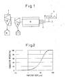
- an inorganic oxide serving as a raw material is brought into a high-temperature flame to thereby melt the oxide, and the thus-melted oxide is formed into spherical particles by means of surface tension of the melted oxide.
- a metal may be employed as a raw material. In such a case, high-temperature oxidation and melting-spheroidization of a metal occur concurrently.
- the surfaces of inorganic particles exhibit hydrophilicity.
- inorganic particles serving as a filler are added to an organic polymer material
- hydrophobicity must be imparted to the surfaces of the inorganic particles.
- sufficient adhesion fails to be established at the interface between the filler and the organic polymer material, and the filling ratio of the filler is lowered.
- the particles are subjected to surface treatment by use of, for example, a silane coupling agent or a titanium coupling agent.
- Such a surface treatment agent has a molecular structure including a hydrophobic group such as an alkyl group, and a hydrolyzable functional group such as a methoxy group or an ethoxy group.
- a methoxy group or an ethoxy group of such a surface treatment agent undergoes hydrolysis, for example, a silanol group is formed, and the thus-formed silanol group is bonded to the surfaces of the inorganic particles. Since the thus-bonded molecules of the surface treatment agent have a hydrophobic group such as an alkyl group, the surfaces of the inorganic particles exhibit high hydrophobicity.
- the above-described surface treatment technique is widely employed (e.g., NUC Silane Coupling Agent Catalogue produced by Nippon Unicar Co., Ltd.).
- Composite particles will next be described.
- composite particles are formed through bonding between large-size particle (hereinafter referred to as “mother particles”) and small-size particles (hereinafter referred to as “child particles”).
- Mother particles are employed for effectively obtaining functions of child particles.
- fine particles having functions of interest are called “child particles”
- mother particles fine particles having functions of interest
- mother particles particles employed for effectively obtaining the functions
- Mother particles are bonded to child particles by means of, for example, a high-speed gas impact technique for mechanically bonding mother particles to child particles (Japanese Patent Publication ( kokoku ) No. 3-2009 and Japanese Patent Application Laid-Open ( kokai ) No. 6-210152 ), or a mechanofusion technique (Japanese Patent No. 2672671 ).
- a high-speed gas impact technique for mechanically bonding mother particles to child particles Japanese Patent Application Laid-Open ( kokai ) No. 6-210152
- a mechanofusion technique Japanese Patent No. 2672671 .
- such bonding is attained by means of, for example, a Hybridization System (registered trademark, product of Nara Machinery Co., Ltd.) or a Mechanofusion System (registered trademark, product of Hosokawa Micron Corporation).
- Examples of the apparatus employed for attaining such bonding include a rolling ball mill, a high-speed rolling mill, and a medium stirring mill.
- the surfaces of mother particles and child particles are activated by means of, for example, impact energy, friction energy, or shear energy of milling media, which energy is applied to the mother particles and child particles, whereby the mother particles are bonded to the child particles.
- the mother particles may be milled and formed into fine particles.
- An object of the present invention is to provide a novel method for modifying the surfaces of particles, which method enables production, at low cost, of a filler suitable for use in a highly viscous composition such as an organic polymer composition or a silicon-containing polymer composition.
- a filler suitable for use in a highly viscous composition such as an organic polymer composition or a silicon-containing polymer composition.
- inorganic powder has been employed as a filler in a composition, in order to enhance characteristics of the composition, such as thermal conductivity, flame retardancy, and insulating property.
- the inorganic powder (filler) is required to exhibit high fillability.
- the inorganic powder must exhibit high fluidity, from the viewpoint of handling of the powder during the course of production of the composition.
- a spherical filler of high fillability has preferentially been employed in a matrix, and adhesion of the filler to the matrix has been enhanced by subjecting the filler to surface treatment.
- Hung C-H et al. "Formation of mixed oxide powders in flames. Part I. TiO2-SiO2", Journal of Materials Research, New York, NY, USA, vol. 7, no. 7, 1992, pages 1861-1869 discloses a process for making silica coated titania by adding titanium tetrachloride and silicon tetrachloride into the same flame and choosing conditions such that the titania condenses before silica.
- US 5 512 094 A discloses hollow silica shells that are coated with a finely distributed metal oxide, followed by a heat treatment.
- WO 02/16508 discloses a process for surface modification comprising a precipitation in aqueous phase of the coating component.
- EP 0 506 219 discloses a process for coating a core particle by means of impacts applied in a high velocity gas system.
- a highly viscous composition having a high filler content is readily produced.
- the present invention provides the following.
- powder A and powder B can be brought into a flame, to thereby modify the surfaces of particles of the powder A by means of particles of the powder B.
- the powder B particles do not necessarily uniformly cover the surface of each particle of the powder A while the powder B particles maintain their original shape, and components of the powder B particles may be discretely distributed over the surface of the powder A particle.
- the powder B particles may be melt-bonded, through heating, to the surface of each particle of the powder A such that the original shape of the powder B particles is not observed on the surface of the powder A particle. In such a case, the powder B particles exhibit remarkable effect of modifying the surface of the powder A.
- the surfaces of the powder A particles are modified by means of the powder B particles.
- association and growth of a plurality of particles occur, forming particles of large size.
- powder A and powder B are brought into the same high-temperature zone.
- the powder B has a particle size smaller than that of the powder A, conceivably, the powder B has larger heat-receiving area, and melting of the powder B occurs more readily. Therefore, through regulation of, for example, the amount of a combustible gas to be combusted, conditions for suppressing association and growth of the powder A particles and for melt-bonding the powder B particles to the powder A particles can be determined.
- the powder in the present invention is obtained through association or collision of the powder B particles with the powder A particles, and bonding of the powder B particles to the powder A particles.
- the thus-associated particles are highly likely to collide with and be bonded to the powder A particles before sufficient growth of the associated particles occurs.
- the reason for this is considered to be as follows. In a gas stream, small-size particles move much faster than large-size particles. Even in the case where the thus-associated and grown powder B particles collide with and are bonded to the powder A particles, when the ratio between the particle size of the powder A particles and that of the powder B particles falls within a predetermined range, the effect of modifying the surface of the powder A is obtained.
- the surfaces of the powder A particles are modified through bonding of the powder B particles which have undergone flame treatment to the surfaces of the powder A particles. Therefore, even when the powder A is formed of the same material as the powder B, the surface modification effect is obtained.
- the form, crystal state, etc. of the powder B particles on the surfaces of the powder A particles can be controlled by regulating the flame treatment conditions.
- the surfaces of the powder A particles can be partially or entirely converted to have a chemical composition of the powder B.
- powder A can be brought into a high-temperature flame several times, to thereby modify the surface of the powder A.
- sufficient surface modification fails to be attained, whereas when sufficient surface modification is to be attained, the interior of the particles is adversely affected by heat, or the particles are melted to form large particles; i.e., difficulty is encountered in modifying merely the particle surfaces to a target level.
- the method of the present invention in which powder is brought into a flame several times, to thereby repeat modification of the surface of the powder, merely the surfaces of particles of the powder can be modified to a target level.
- the number of the flame treatment cycle closely relates to the flame conditions and the melting point of powder to be treated.
- the optimal number of the treatment cycle varies with the temperature of a flame and the residence time of the powder within the flame. When the temperature of the flame is lowered, and the number of the treatment cycles is increased, the surface conditions of the powder is readily regulated, but production cost increases. In contrast, when the temperature of the flame is excessively high, the powder tends to undergo excessive thermal denaturation. Therefore, the optimal number of the treatment cycle is determined in consideration of balance between flame combustion conditions and powder surface treatment; specifically, is determined on the basis of the results of preliminary tests.
- Powder A may be formed of particles of an oxide of, for example, Al, Mg, Ca, Ti, or Si, or particles of a mixed crystal of such oxides.
- powder A may be formed of particles of aluminum oxide, magnesium oxide, calcium oxide, titanium oxide, silica, or a similar oxide, or particles of a mixed crystal of such oxides.
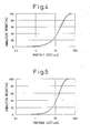
- Powder A has an average particle size of 0.5 to 200 ⁇ m, preferably 1 to 100 ⁇ m, more preferably 2 to 80 ⁇ m, as measured by use of a laser diffraction/scattering particle size analyzer. Particles of powder A may be obtained by any technique.
- the particle size (BET-based particle size) of powder B is preferably 1/10 or less, more preferably 1/20 or less, the average particle size of powder A as measured by use of a laser diffraction/scattering particle size analyzer.
- the particle size of powder B exceeds the above range, particles which have undergone surface modification have excessively rough surfaces, and the particles exhibit poor fillability. For example, when such particles are kneaded with a resin, the viscosity of the resultant resin composition fails to be lowered substantially.
- Powder B may be produced by means of, for example, a vapor-phase process in which a metal halide having a relatively low boiling point is gasified and decomposed, to thereby produce metal oxide powder (e.g., the following patent document: WO 01/16027 ).
- a metal halide having a relatively low boiling point is gasified and decomposed, to thereby produce metal oxide powder
- WO 01/16027 a metal halide having a relatively low boiling point
- such a process is used to produce alumina, titania, silica, or a composite product of such oxides.
- Powder produced through such a vapor-phase process has a chain structure in which primary particles are weakly point-bonded together to form a long chain.
- Oxide powder produced through the vapor-phase process is suitable as powder B, which serves as a raw material for the powder in the present invention, because the oxide powder has the aforementioned chain structure.
- the powder having the chain structure is sensitive to the resistance of gas flow, and is readily transported.
- the powder is sufficiently dispersed by the shearing force from gas flow, and then brought into a flame. Therefore, the powder is readily dispersed by means of a flame of a low Reynolds number, and the contact probability of the powder with powder A can be enhanced.
- transition alumina e.g., , ⁇ -, ⁇ -, ⁇ , or ⁇ -alumina
- a powdery substance of high temperature phase is selected as powder A, for example, solely the powder B is readily melted.
- Powder A and powder B are mixed together, and the resultant mixture is brought into a flame.
- powder A and powder B may be separately brought into a flame.
- the ratio by amount between powder A and powder B is appropriately determined in accordance with the ratio between the particle size of powder A and that of powder B, preferred surface modification can be attained.
- the amount of powder A is preferably 50 mass% to 99 mass% inclusive, more preferably 60 mass% to 98 mass% inclusive, on the basis of the total mass of powder A and powder B.
- a carrier gas such as nitrogen or air may be employed.
- these powders are mixed together, when the amount of a carrier gas is regulated such that the Reynolds number of the carrier gas which flows through an inlet tube is 3,000 to 80,000 inclusive, preferably 5,000 to 50,000 inclusive, these powders can be uniformly dispersed in a flame.
- the Reynolds number is below the above range, sufficient mixing of the powders fails to be attained, whereas, when the Reynolds number exceeds the above range; i.e., when the amount of the carrier gas is increased, the temperature of a reaction zone is lowered.
- a high-temperature zone is employed for bonding particles of powder B to the surfaces of particles of powder A.
- the simplest apparatus for generating a high-temperature zone is a burner.
- the length and temperature of a high-temperature zone can be regulated.
- any combustible gas may be employed in a burner.
- the combustible gas is any species selected from among methane, ethane, propane, ethylene, propylene, acetylene, butane, LPG, hydrogen, and carbon monoxide; or a gas mixture thereof. More preferably, the combustible gas is LPG.
- a critical point is to regulate the temperature of a combustion zone to a temperature nearly equal to the melting point of powder B.
- powder A and powder B an LPG-oxygen burner or a hydrogen-oxygen burner can be employed.
- the burner preferably has a coaxial triple-tube structure capable of simultaneously bringing powder A and powder B from the same nozzle into a flame.
- a combustible gas such as LPG is caused to pass through the middle tube
- a combustion-supporting gas such as oxygen or air is caused to pass through the outermost tube.
- the combustion-supporting gas may be any oxygen-containing gas, but is preferably oxygen.
- Powder A and Powder B may be brought from different nozzles into a flame.
- Such a powder introduction form is advantageous in that the thermal history of powder A and the thermal history of powder B can be separately controlled by regulating, for example, the positions of the nozzles within a flame separately.
- the flow rate of raw material/carrier gas spurted out from a nozzle is 3 m/second to 100 m/second inclusive (the flow rate is obtained by dividing the amount of a gas spurted out from a nozzle at a normal state (Nm 3 /second) by the area of the spurt outlet of the nozzle (m 2 ), the same shall apply hereinafter), preferably 5 m/second to 80 m/second inclusive.
- the diameter of the innermost tube and other parameters are determined such that the tube Reynolds number becomes 3,000 or more, preferably 5,000 or more. Under the above conditions, in general, the raw material powder can be dispersed sufficiently.
- the flow rate of a combustible gas spurted out from a nozzle is determined to be 0.8 times to 4 times, preferably 0.9 times to twice, that of the spurted raw material/carrier gas.
- the flow rate of an oxidative gas spurted out from a nozzle is determined to be 1 to 11 times, preferably 1.5 to 6 times, that of the spurted raw material/carrier gas.
- the thus-produced powder is collected by use of, for example, a cyclone or a bag filter, whereby a final product is obtained.
- the thus-obtained powder product has an average particle size falling within a range of 0.5 to 250 ⁇ m as measured by means of a laser diffraction/scattering particle size analysis, and the surface thereof is modified by means of powder B particles.
- Equipment conditions and production conditions e.g., the flow rate of raw material/carrier gas spurted out from a nozzle
- Powder A which has been brought into a flame is quickly cooled, at the time, when only the surface - thereof undergoes thermal modification.
- the high-temperature zone of a flame is present only within a limited area of the flame, and therefore, an operation for quickly cooling the powder A is not necessarily performed.
- the powder A is subjected to the high-temperature flame treatment cycle several times.
- the optimal number of the treatment cycle is determined on the basis of the results of practical evaluation of a powder product which has been produced by bringing powder A into a flame several times.
- the powder in the present invention may further be subjected to surface hydrophobization treatment.
- the powder which has undergone surface hydrophobization treatment exhibits improved affinity to, for example, a resin.
- An agent employed for such surface hydrophobization treatment may be a coupling agent such as an alkoxide of Si or Ti.
- the surface hydrophobization treatment is carried out by means of a generally employed surface hydrophobization treatment method; for example, a dry treatment method in which a surface treatment agent is added to powder, and the resultant mixture is stirred and heated, or a wet treatment method in which a surface treatment agent is added to an aqueous slurry containing powder.
- the surface-modified powder in the present invention can be employed as a filler or a modifier for resin products and rubber products; or employed as an additive to paper, paint, and printing ink.
- the surface-modified powder can be employed, as inorganic oxide powder, in cosmetic compositions, ceramic products, electronic parts, luminescent materials, etc.
- the surface-modified powder is suitable for use as, for example, a high thermally conductive filler requiring fillability and dispersibility to a medium.
- the surface-modified powder in the present invention may be added to, for example, an organic polymer to thereby prepare a composition.
- the organic polymer include a synthetic thermoplastic resin, a synthetic thermosetting resin, and a natural resin.
- Specific examples of the organic polymer include polyolefins such as polyethylene, polypropylene, and polystyrene; polyamides such as nylon 6, nylon 66, and aramid; polyesters such as polyethylene terephthalate and unsaturated polyesters; polyvinyl chloride; polyvinylidene chloride; polyethylene oxide; polyethylene glycol; silicone resin; polyvinyl alcohol; vinylacetal resin; polyacetate; ABS resin; epoxy resin; imide-containing epoxy resin; vinyl acetate resin; cellulose derivatives such as cellulose and rayon; urethane resin; polycarbonate; urea resin; fluorine-containing resin; polyvinylidene fluoride; phenolic resin; celluloid; chitin; starch sheet; acrylic resin; melamine
- the surface-modified powder in the present invention may be added to, for example, a silicon-containing polymer to thereby prepare a composition.
- the organic polymer composition or silicon-containing polymer composition containing the surface-modified powder may be employed in the form of, for example, a coating composition, a compound (e.g., a resin composition containing the powder), or a masterbatch for a molded product containing a large amount of the powder.
- the organic polymer composition or silicon-containing polymer composition may contain an additive such as an antioxidant, an antistatic agent, and a fatty acid metallic salt.
- the amount of the surface-modified powder in the present invention in the organic polymer composition or silicon-containing polymer composition varies in accordance with use of the composition.
- the amount of the powder is preferably 0.01 to 95 mass%, more preferably 20 to 90 mass%, on the basis of the entire mass of the composition.
- the organic polymer composition or silicon-containing polymer composition can be subjected to molding, to thereby form, for example, fiber, film, and plastic molded products.
- molded products include heat-storing fiber, heat-generating fiber, UV-shielding fiber, UV-shielding film, high thermally conductive material, high thermally conductive sheet, high thermally conductive film, insulating material, insulating film, and insulating sheet.
- a coating agent can be prepared.
- the binder material may be an organic or inorganic binder.
- organic binder examples include polyvinyl alcohol, melamine resin, urethane resin, celluloid, chitin, starch sheet, polyacrylamide, acrylamide, polyesters such as unsaturated polyesters, polyvinyl chloride, polyvinylidene chloride, polyethylene oxide, polyethylene glycol, silicone resin, vinylacetal resin, epoxy resin, vinyl acetate resin, urethane resin, urea resin, fluorine-containing resin, polyvinylidene fluoride, and phenolic resin.
- the inorganic binder examples include zirconium compounds such as zirconium oxychloride, zirconium hydroxychloride, zirconium nitrate, zirconium sulfate, zirconium acetate, ammonium zirconium carbonate, and zirconium propionate; silicon compounds such as alkoxysilane and silicate; and alkoxides of metals such as aluminum and titanium.
- zirconium compounds such as zirconium oxychloride, zirconium hydroxychloride, zirconium nitrate, zirconium sulfate, zirconium acetate, ammonium zirconium carbonate, and zirconium propionate
- silicon compounds such as alkoxysilane and silicate
- alkoxides of metals such as aluminum and titanium.
- the amount of the binder contained in the coating agent is preferably 0.01 mass% to 20 mass%, particularly preferably 1 mass% to 10 mass%.
- the thus-produced powder in the present invention may be applied to the surface of a structure.
- the structure may be formed from an inorganic material such as metal, concrete, glass, or ceramic; or an organic material such as paper, plastic, timber, or leather.
- the structure may be formed from a combination of an inorganic material and an organic material.
- Examples of the structure include building materials, machinery, vehicles, glass products, electric appliances, agricultural materials, electronic apparatus, tools, tableware, bath products, toiletry products, furniture, clothing, cloth products, fibers, leather products, paper products, sporting goods, futon, containers, eyeglasses, signboards, piping, wiring, brackets, sanitary materials, automobile parts, outdoor goods such as tents, stockings, socks, gloves, and masks.
- the aforementioned organic polymer composition, silicon-containing polymer composition, or coating agent may be applied directly to a structure, or may be applied onto a structure having a coating film thereon.
- another coating film may be formed on the structure coated with the powder.
- the powder in the present invention may be incorporated into, for example, a cosmetic composition.
- a cosmetic composition containing the powder in the present invention provides excellent smoothness.
- the powder-containing cosmetic composition may contain an additive which is generally employed in a cosmetic composition, such as an oil, a whitening agent, a humectant, an anti-aging agent, an emollient, an extract, an anti-inflammatory agent, an antioxidant, a surfactant, a chelating agent, an antibacterial agent, a preservative, an amino acid, a sugar, an organic acid, an alcohol, an ester, fat and oil, a hydrocarbon, an anti-UV agent, or inorganic powder.
- an additive which is generally employed in a cosmetic composition, such as an oil, a whitening agent, a humectant, an anti-aging agent, an emollient, an extract, an anti-inflammatory agent, an antioxidant, a surfactant, a chelating agent, an antibacterial agent, a preservative, an amino acid
- additives such as ethanol, isopropanol, butyl alcohol, and benzyl alcohol
- polyhydric alcohols such as glycerin, propylene glycol, sorbitol, polyethylene glycol, dipropylene glycol, 1,3-butylene glycol, and 1,2-pentanediol
- sugars such as sorbitol
- disaccharides such as trehalose
- humectants such as hyaluronic acid and water-soluble collagen
- emollients such as hydrogenated squalane, vegetable oils (e.g., olive oil and jojoba oil), and ceramides
- whitening agents such as stable ascorbic acid derivatives (e.g., magnesium ascorbate phosphate and ascorbic acid glycoside), arbutin, kojic acid, ellagic acid, Lucinol, and chamomile extract
- anti-inflammatory agents such as allantoin, glycyrrhet
- All the components of the cosmetic composition in the present invention, except for the powder in the present invention, can be produced by means of a generally employed technique.
- Fig. 1 schematically shows a typical production apparatus for carrying out the present invention, but the production apparatus which can be employed in the present invention is not limited to the apparatus shown in Fig. 1 .
- the present invention will next be described with reference to this figure.
- Reference numeral 1 denotes a feeder/hopper for feeding, into a flame, a predetermined amount of a mixture of powder A and powder B or a predetermined amount of powder A.
- Reference numeral 2 denotes a carrier gas for transporting the raw material powder into a flame.
- a carrier gas for example, air or nitrogen gas is employed as the carrier gas. More uniform mixing of the powder A and the powder B is attained by means of the carrier gas.
- the carrier gas must assume a turbulent state. The diameter of a tube through which the carrier gas passes and the flow rate of the carrier gas are determined such that the tube Reynolds number of the carrier gas becomes 3,000 to 80,000 inclusive, preferably 5,000 to 50,000 inclusive.
- Reference numeral 3 denotes a combustible gas for forming a combustion flame
- reference numeral 4 denotes a combustion-supporting gas (may be referred to as "oxidative gas").
- the carrier gas containing the raw material powder, the combustible gas, and the combustion-supporting gas are brought into a combustion tube 5, to thereby form a flame.
- a combustion tube of coaxial triple-tube structure is employed; the raw material-containing carrier gas is caused to flow through the innermost tube, the combustion-supporting gas is caused to flow through the outermost tube, and the combustible gas is caused to flow through the middle tube.
- the combustion-supporting gas may be divided into a plurality of portions, before being brought into the combustion tube.
- the tube is preferably formed of, for example, a stainless steel tube equipped with a water cooling jacket.
- a ceramic tube is not suitable as the combustion tube, as it does not exhibit resistance to drastic change in temperature.
- Powder produced in the combustion tube 5 is trapped in a cyclone 6, and then collected in a product hopper 7.
- the powder which remains in the cyclone 6 after classification is trapped in a bag filter 8, and then collected in a fine powder hopper 9.
- the powder collected in the fine powder hopper 9 can be recycled as a raw material.
- a combustion exhaust gas is discharged to the outside of the apparatus.
- powder collected in the product hopper 7 is fed into the hopper 1, and is again brought into the flame.
- the powder obtained through this procedure is collected as a final product in the product hopper 7.
- the flame treatment is performed several times.
- Gaseous titanium tetrachloride (concentration: 100%) was preliminarily heated to 1,000°C. Separately, a gas mixture of oxygen (96 vol.%) and steam (4 vol.%) was preliminarily heated to 1,000°C.
- the titanium tetrachloride gas and the gas mixture were brought into a reaction tube through a coaxial parallel-flow nozzle at flow rates of 45 m/second and 50 m/second, respectively.
- the titanium tetrachloride gas was fed through the inner tube.
- the flow rates of the titanium tetrachloride gas and the gas mixture in the reaction tube were found to be 8 m/second (calculated value) at a reaction temperature of 1,630°C.
- the thus-produced titanium dioxide powder was found to have a BET-based particle size of 260 nm and an average particle size of 0.6 ⁇ m as measured by use of a laser diffraction/scattering particle size analyzer.
- the titanium dioxide powder was employed as powder B.
- True spherical alumina powder having an average particle size of 11 ⁇ m as measured by use of a laser diffraction/scattering particle size analyzer was employed as powder A.
- the true spherical alumina powder was produced through the flame fusion process from alumina powder having an average particle size of 10 ⁇ m produced by means of the Bayer method.
- the true spherical alumina powder was found to have an ⁇ -alumina content of 70%.
- Fig. 2 shows the particle size distribution of particles of the powder A
- Fig. 3 shows the shape of the powder A particles.
- the powder A was produced under the following production conditions: flow rate of a carrier gas spurted out from a nozzle: 40 m/second, tube Reynolds number: 8,000, combustible gas: LPG, flow rate of the combustible gas spurted out from a nozzle: 60 m/second, oxidative gas: oxygen, flow rate of the oxidative gas spurted out from a nozzle: 80 m/second.
- a sufficient amount of oxygen was brought into a reaction tube such that LPG was theoretically completely combusted by means of the oxygen.
- the alumina powder having an average particle size of 10 ⁇ m produced by means of the Bayer method was brought into the reaction tube together with the carrier gas, to thereby produce the true spherical alumina powder having an average particle size of 11 ⁇ m.
- the powder A and the powder B were subjected to thermal treatment as described below.
- LPG was spurted out from the nozzle of the middle tube of a coaxial triple-tube burner at a flow rate of 60 m/second, and oxygen was spurted out from the nozzle of the outermost tube of the burner at a flow rate of 80 m/second, to thereby form a combustion flame.
- the powder A and the powder B were vibration-mixed together in a resin bag such that the ratio by mass of the powder A to the powder B was 9 : 1, and then the resultant mixture was fed into a raw material hopper.
- the powder mixture was fed through the innermost tube at a feed rate of 6 kg/hour together with air serving as a carrier gas, and spurted out from the nozzle of the tube to the above-formed combustion flame.
- the flow rate of the carrier gas containing the raw material powders spurted out from the nozzle was 43 m/second, and the tube Reynolds number of the carrier gas was 12,000.
- the thus-combusted gas containing the solid was subjected to solid-gas separation in a cyclone, and the resultant powder was collected.
- the thus-obtained powder had a white color and a spherical shape.
- the powder was subjected to particle size analysis by use of a laser diffraction/scattering particle size analyzer (model: SALD-2000J, product of Shimadzu Corporation), and the average particle size of the powder was found to be 14 ⁇ m.
- the ⁇ -alumina content of the powder was obtained on the basis of an XRD peak corresponding to alumina, and was found to be 47%.
- Fig. 3 shows the particle size distribution of particles of the powder. As is clear from this figure, the particle size distribution of the powder particles is almost the same as that of the raw material powder particles ( Fig. 2 ).
- the thus-obtained powder (250 parts by mass) and an epoxy resin (epoxy resin AER-250, product of Asahi Kasei Corporation) (100 parts by mass) were subjected to kneading for five minutes and then to defoaming for one minute by use of an autorotation/revolution-system kneading/defoaming machine (Awatori Rentaro AR-250, product of Thinky Corporation). After the temperature of the resultant product was adjusted to 25°C, the viscosity of the product was measured by use of a B-type viscometer. The viscosity was found to be 1,500 cP.
- the thus-produced aluminum oxide powder was found to have a BET-based particle size of 37 nm and to predominantly contain a ⁇ -alumina crystal phase.
- the aluminum oxide powder was employed as powder B (raw material).
- True spherical alumina powder having an average particle size of 11 ⁇ m as measured by use of a laser diffraction/scattering particle size analyzer was employed as powder A.
- the true spherical alumina powder was produced through the flame fusion process from alumina powder having an average particle size of 10 ⁇ m produced by means of the Bayer method.
- the true spherical alumina powder was found to have an ⁇ -alumina content of 71%.
- the true spherical alumina powder is the same as the powder A employed in Example 1.
- the powder A and the powder B were subjected to thermal treatment as described below.
- LPG was spurted out from the nozzle of the middle tube of a coaxial triple-tube burner at a flow rate of 60 m/second, and oxygen was spurted out from the nozzle of the outermost tube of the burner at a flow rate of 80 m/second, to thereby form a combustion flame.
- the powder A and the powder B were vibration-mixed together in a resin bag such that the ratio by mass of the powder A to the powder B was 8 : 2, and then the resultant mixture was fed into a raw material hopper.
- the powder mixture was fed through the innermost tube at a feed rate of 4 kg/hour together with air serving as a carrier gas, and spurted out from the nozzle of the tube to the above-formed combustion flame.
- the flow rate of the air spurted out from the nozzle was 48 m/second, and the tube Reynolds number of the air was 14,000.
- the thus-combusted gas containing the solid was subjected to solid-gas separation in a cyclone, and the resultant powder was collected.
- the resultant surface-modified powder had a white color and a spherical shape.
- the powder was subjected to particle size analysis by use of a laser diffraction/scattering particle size analyzer (model: SALD-2000J, product of Shimadzu Corporation), and the average particle size of the powder was found to be 13 ⁇ m.
- the ⁇ -alumina content of the powder was found to be 42%.
- Fig. 5 shows the particle size distribution of particles of the thus-obtained powder
- Fig. 6 shows an SEM photograph of a particle of the powder.
- Example 2 In a manner similar to that of Example 1, the above-obtained powder (250 g) and an epoxy resin (epoxy resin AER-250) (100 g) were subjected to kneading for five minutes and then to defoaming for one minute. After the temperature of the resultant product was adjusted to 25°C, the viscosity of the product was measured by use of a B-type viscometer. The viscosity was found to be 1,140 cP.
- the thus-produced aluminum oxide powder was found to have a BET-based particle size of 15 nm and to predominantly contain a ⁇ -alumina crystal phase.
- the aluminum oxide powder was employed as powder B (raw material).
- Round-shaped alumina powder (AS-20, product of Showa Denko K.K.) having an average particle size of 22 ⁇ m, as measured by use of a laser particle size analyzer, was employed as powder A.
- LPG was spurted out from the nozzle of the middle tube of a coaxial triple-tube burner at a flow rate of 45 m/second, and oxygen was spurted out from the nozzle of the outermost tube of the burner at a flow rate of 73 m/second, to thereby form a combustion flame.
- the powder A and the powder B were mixed together such that the ratio by mass of the powder A to the powder B was 9 : 1, and then the resultant mixture was fed into a raw material hopper.
- the powder mixture was fed through the innermost tube at a feed rate of 4 kg/hour together with air serving as a carrier gas, and spurted out from the nozzle of the tube to the above-formed combustion flame.
- the flow rate of the air spurted out from the nozzle was 20 m/second, and the tube Reynolds number of the air was 6,000.
- the thus-combusted gas containing the solid was subjected to solid-gas separation in a cyclone, and the resultant powder was collected.
- the resultant surface-modified powder had a white color and a spherical shape.
- the powder was subjected to particle size analysis by use of a laser diffraction/scattering particle size analyzer (model: SALD-2000J, product of Shimadzu Corporation), and the average particle size of the powder was found to be 25 ⁇ m.
- the ⁇ -alumina content of the powder was found to be 78%.
- Example 2 In a manner similar to that of Example 1, the above-obtained powder (250 g) and an epoxy resin (epoxy resin AER-250) (100 g) were subjected to kneading for five minutes and then to defoaming for one minute. After the temperature of the resultant product was adjusted to 25°C, the viscosity of the product was measured by use of a B-type viscometer. The viscosity was found to be 730 cP.
- powder A (raw material), there was employed the powder A employed in Example 2, which had been subjected to thermal treatment once.
- LPG was spurted out from the nozzle of the middle tube of a coaxial triple-tube burner at a flow rate of 60 m/second, and oxygen was spurted out from the nozzle of the outermost tube of the burner at a flow rate of 80 m/second, to thereby form a combustion flame.
- the powder A was brought into the thus-formed combustion flame.
- the raw material powder was fed through the innermost tube at a feed rate of 4 kg/hour together with air serving as a carrier gas, and spurted out from the nozzle of the tube to the combustion flame.
- the flow rate of the air spurted out from the nozzle was 40 m/second, and the tube Reynolds number of the air was 18,000.
- the thus-combusted gas containing the solid was subjected to solid-gas separation in a cyclone, and the resultant powder was collected.
- the thus-obtained powder assumed a white color and a spherical shape.
- the powder was subjected to particle size analysis by use of a laser diffraction/scattering particle size analyzer (model: SALD-2000J, product of Shimadzu Corporation), and the average particle size of the powder was found to be 13 ⁇ m.
- the ⁇ -alumina content of the powder was found to be 55%.
- Example 2 In a manner similar to that of Example 1, the above-obtained powder (250 g) and an epoxy resin (epoxy resin AER-250) (100 g) were subjected to kneading for five minutes and then to defoaming for one minute. After the temperature of the resultant product was adjusted to 25°C, the viscosity of the product was measured by use of a B-type viscometer. The viscosity was found to be 1,250 cP.
- the powder A and powder B employed in Example 1 were vibration-mixed together in a resin bag such that the ratio by mass of the powder A to the powder B was 9 : 1.
- the resultant powder mixture (250 g) and an epoxy resin (epoxy resin AER-250, product of Asahi Kasei Corporation) (100 g) were subjected to kneading for five minutes and then to defoaming for one minute by use of an autorotation/revolution-system kneading/defoaming machine (Awatori Rentaro AR-250, product of Thinky Corporation). After the temperature of the resultant product was adjusted to 25°C, the viscosity of the product was measured by use of a B-type viscometer.
- the viscosity was found to be 5,000 cP or more.
- a product containing the powder A and the aforementioned epoxy resin was prepared, and the viscosity of the product was measured.
- the viscosity was found to be 5,000 cP or more.
- the powder A and powder B employed in Example 2 were vibration-mixed together in a resin bag such that the ratio by mass of the powder A to the powder B was 8 : 2.
- the resultant powder mixture (250 g) and an epoxy resin (epoxy resin AER-250, product of Asahi Kasei Corporation) (100 g) were subjected to kneading for five minutes and then to defoaming for one minute by use of an autorotation/revolution-system kneading/defoaming machine (Awatori Rentaro AR-250, product of Thinky Corporation). After the temperature of the resultant product was adjusted to 25°C, the viscosity of the product was measured by use of a B-type viscometer. The viscosity was found to be 5,000 cP or more.
- the powder A and powder B employed in Example 3 were vibration-mixed together in a resin bag such that the ratio by mass of the powder A to the powder B was 9 : 1.
- the resultant powder mixture (250 g) and an epoxy resin (epoxy resin AER-250, product of Asahi Kasei Corporation) (100 g) were subjected to kneading for five minutes and then to defoaming for one minute by use of an autorotation/revolution-system kneading/defoaming machine (Awatori Rentaro AR-250, product of Thinky Corporation). After the temperature of the resultant product was adjusted to 25°C, the viscosity of the product was measured by use of a B-type viscometer.
- the viscosity was found to be 5,000 cP or more.
- a product containing the powder A and the aforementioned epoxy resin was prepared, and the viscosity of the product was measured.
- the viscosity was found to be 4,200 cP.
- the present invention provides a novel method for modifying the surfaces of particles, which can modify only the surfaces of particles to a target level by means of flame treatment.
- a highly viscous composition e.g., an organic polymer composition or a silicon-containing polymer composition
- the surface-modified powder exhibits the effect of sufficiently lowering the viscosity of the resultant composition, as compared with powder which has not undergone such surface modification. Therefore, even when the amount of the surface-modified powder in the composition is increased, molding of the composition can be readily performed.
- the surface-modified powder is very useful as, for example, a thermally-conductive filler, an insulating filer, or a heat-resistant filler, which requires high fillability. Furthermore, by virtue of its high fluidity, the surface-modified powder is suitable for use in, for example, a coating material or a cosmetic composition. In addition, the surface-modified powder can be employed in, for example, a raw material for a ceramic molded product or a luminescent material.
Landscapes
- Chemical & Material Sciences (AREA)
- Engineering & Computer Science (AREA)
- Organic Chemistry (AREA)
- Nanotechnology (AREA)
- Composite Materials (AREA)
- Condensed Matter Physics & Semiconductors (AREA)
- General Physics & Mathematics (AREA)
- Materials Engineering (AREA)
- Crystallography & Structural Chemistry (AREA)
- Physics & Mathematics (AREA)
- Compositions Of Macromolecular Compounds (AREA)
- Compounds Of Alkaline-Earth Elements, Aluminum Or Rare-Earth Metals (AREA)
- Oxygen, Ozone, And Oxides In General (AREA)
Claims (10)
- Oberflächenmodifikationsverfahren, welches das Einbringen
eines anorganischen Oxidpulvers A mit einer mittleren Teilchengröße innerhalb eines Bereichs von 0,5 bis 200 µm, gemessen durch Laserbeugungs/Streuungs-Teilchengrößenanalyse und
eines anorganischen Oxidpulvers B mit einer Teilchengröße, berechnet auf der Grundlage seiner spezifischen Oberfläche nach BET (im Folgenden einfach als "Teilchengröße auf Grundlage von BET" bezeichnet), von 100 nm oder weniger,
in eine durch Verwendung eines brennbaren Gases und eines verbrennungsfördernden Gases gebildete Flamme umfasst,
wobei die Oberflächen der Teilchen des Pulvers A durch die Teilchen des Pulvers B modifiziert werden. - Oberflächenmodifikationsverfahren, welches das Einbringen
eines anorganischen Oxidpulvers A mit einer mittleren Teilchengröße im Bereich von 0,5 bis 200 µm, gemessen durch Laserbeugungs/Streuungs-Teilchengrößenanalyse, in eine durch Einsatz eines brennbaren Gases und eines verbrennungsfördernden Gases gebildete Flamme,
und
das erneute Einbringen des erhaltenen Pulvers in eine unter Einsatz eines brennbaren Gases und eines verbrennungsfördernden Gases gebildete Flamme umfasst, wobei die Oberflächen der Teilchen des Pulvers A modifiziert werden. - Oberflächenmodifikationsverfahren nach Anspruch 1 oder 2, wobei das brennbare Gas ein beliebiges Gas, das unter Methan, Ethan, Propan, Ethylen, Propylen, Acetylen, Butan, LPG, Wasserstoff und Kohlenmonoxid ausgewählt ist, oder ein Gasgemisch davon ist.
- Oberflächenmodifikationsverfahren nach einem der Ansprüche 1 bis 3, wobei die Flamme durch einen koaxialen Dreiröhrchenbrenner mit einem innersten Röhrchen, einem Zwischenröhrchen und einem äußersten Röhrchen gebildet ist, wobei das Pulver oder die Pulver durch das innerste Röhrchen geleitet werden, ein brennbares Gas durch das Zwischenröhrchen geleitet wird und ein verbrennungsförderndes Gas durch das äußerste Röhrchen geleitet wird.
- Oberflächenmodifikationsverfahren nach einem der Ansprüche 1 bis 4, wobei Pulver A und Pulver B gegebenenfalls zusammen mit einem Trägergas in die Flamme gesprüht werden.
- Oberflächenmodifikationsverfahren nach einem der Ansprüche 1 bis 5, wobei Pulver A Teilchen eines Oxids von Al, Mg, Ca, Ti oder Si oder Teilchen eines Mischkristalls von solchen Oxiden umfasst.
- Oberflächenmodifikationsverfahren nach einem der Ansprüche 1 bis 6, wobei Pulver B Teilchen eines Oxids von Al, Ti oder Si oder Teilchen eines Mischkristalls solcher Oxide umfasst.
- Oberflächenmodifikationsverfahren nach Anspruch 6 oder 7, wobei Pulver A Teilchen mit einem die folgende Formel (1) definierten sphärischen Ausmaß von mindestens 0,7 umfasst:

- Oberflächenmodifikationsverfahren nach einem der Ansprüche 6 bis 8, wobei die Teilchengröße auf Grundlage von BET des Pulvers B 1/10 oder weniger der durch Laserbeugungs/Streuungs-Teilchengrößenanalyse gemessenen mittleren Teilchengröße des Pulvers A ist.
- Oberflächenmodifikationsverfahren nach einem der Ansprüche 6 bis 9, wobei die Menge des Pulvers A 50 Massen-% bis einschließlich 99 Massen-% auf der Grundlage der Gesamtmasse des Pulvers A und des Pulvers B ist.
Applications Claiming Priority (5)
| Application Number | Priority Date | Filing Date | Title |
|---|---|---|---|
| JP2003016402A JP2004262674A (ja) | 2003-01-24 | 2003-01-24 | 無機酸化物粉体の表面改質方法とそれによって製造された粉体、およびその用途 |
| JP2003016402 | 2003-01-24 | ||
| US44352903P | 2003-01-30 | 2003-01-30 | |
| US443529P | 2003-01-30 | ||
| PCT/JP2004/000616 WO2004065495A2 (en) | 2003-01-24 | 2004-01-23 | Surface modification method for inorganic oxide powder, powder produced by the method and use of the powder |
Publications (2)
| Publication Number | Publication Date |
|---|---|
| EP1587883A2 EP1587883A2 (de) | 2005-10-26 |
| EP1587883B1 true EP1587883B1 (de) | 2015-06-10 |
Family
ID=32775194
Family Applications (1)
| Application Number | Title | Priority Date | Filing Date |
|---|---|---|---|
| EP04704755.0A Expired - Lifetime EP1587883B1 (de) | 2003-01-24 | 2004-01-23 | Verfahren zur oberflächenmodifizierung von anorganischen oxidpulvern, pulver die nach diesem verfahren hergestellt wurden und verwendung derselben |
Country Status (3)
| Country | Link |
|---|---|
| US (1) | US7425287B2 (de) |
| EP (1) | EP1587883B1 (de) |
| WO (1) | WO2004065495A2 (de) |
Cited By (1)
| Publication number | Priority date | Publication date | Assignee | Title |
|---|---|---|---|---|
| EP3294919B1 (de) * | 2015-05-13 | 2024-04-24 | Oerlikon Metco (Japan) Ltd. | Leistung zum thermischen spritzen, verfahren zum thermischen spritzen und thermisch gespritzte beschichtung |
Families Citing this family (11)
| Publication number | Priority date | Publication date | Assignee | Title |
|---|---|---|---|---|
| CN100337986C (zh) * | 2005-11-24 | 2007-09-19 | 武汉理工大学 | 一种核壳复合陶瓷颗粒的制备方法 |
| CN101568858B (zh) | 2006-12-27 | 2012-07-25 | 花王株式会社 | 光扩散性部件 |
| JP5602996B2 (ja) * | 2008-02-08 | 2014-10-08 | 日本化学工業株式会社 | 粉末状のシリカコンポジット粒子及びその製造方法、シリカコンポジット粒子分散液、並びに樹脂組成物 |
| KR101505237B1 (ko) * | 2008-04-30 | 2015-03-23 | 덴키 가가쿠 고교 가부시기가이샤 | 알루미나 분말, 그의 제조 방법 및 그것을 사용한 수지 조성물 |
| CN101434837B (zh) * | 2008-12-09 | 2011-08-10 | 彩虹集团电子股份有限公司 | 一种紫外激发红色荧光粉的表面处理方法 |
| US10005127B2 (en) | 2014-01-24 | 2018-06-26 | United Technologies Corporation | Powder improvement for additive manufacturing |
| JP6076510B2 (ja) * | 2014-02-14 | 2017-02-08 | 宇部マテリアルズ株式会社 | 酸化マグネシウム、熱伝導性フィラー及びこれを含む熱伝導性樹脂組成物並びに酸化マグネシウムの製造方法 |
| CN107001506A (zh) * | 2014-11-24 | 2017-08-01 | 尤尼威蒂恩技术有限责任公司 | 包含颗粒的组合物 |
| CN106065202B (zh) * | 2016-07-19 | 2018-11-06 | 长沙欧赛新材料有限公司 | 一种连续性粉体表面改性机 |
| TWI617533B (zh) | 2016-12-09 | 2018-03-11 | 財團法人工業技術研究院 | 表面改質陶瓷粉體及其應用 |
| CN107522478A (zh) * | 2017-08-24 | 2017-12-29 | 广州普华灵动机器人技术有限公司 | 陶瓷燃烧器制作工艺方法与陶瓷燃烧器 |
Family Cites Families (19)
| Publication number | Priority date | Publication date | Assignee | Title |
|---|---|---|---|---|
| US5340781A (en) * | 1986-07-14 | 1994-08-23 | Showa Denko Kabushiki Kaisha | Spherical corundum particles, process for preparation thereof and rubber or plastic composition having high thermal conductivity and having spherical corundum paticles incorporated therein |
| JPS63185803A (ja) | 1986-08-08 | 1988-08-01 | Ube Ind Ltd | 球状複合金属酸化物粒子及びその製法 |
| JPS63248712A (ja) | 1987-04-01 | 1988-10-17 | Denki Kagaku Kogyo Kk | 無機質充填剤及びその製法 |
| US5140005A (en) * | 1988-02-04 | 1992-08-18 | The Perkin-Elmer Corporation | Ceramic superconductive powder |
| JP2670628B2 (ja) | 1989-01-26 | 1997-10-29 | 日本化学工業株式会社 | 微細な溶融球状シリカの製造方法 |
| JP2826125B2 (ja) | 1989-05-31 | 1998-11-18 | 株式会社クラレ | 回転成形容器およびその製造法 |
| JP2672671B2 (ja) | 1989-10-06 | 1997-11-05 | ホソカワミクロン株式会社 | 複合粒子の製造法 |
| JP2955672B2 (ja) | 1990-03-09 | 1999-10-04 | 日本化学工業株式会社 | 半導体樹脂封止用シリカフィラーおよびその製造方法 |
| JP2941081B2 (ja) * | 1991-03-26 | 1999-08-25 | 株式会社奈良機械製作所 | 結晶性有機化合物の非晶質割合の増加と再結晶化を抑制する方法 |
| JP3002009B2 (ja) | 1991-05-20 | 2000-01-24 | 松下電子工業株式会社 | 半導体装置 |
| US5512094A (en) * | 1992-11-20 | 1996-04-30 | E. I. Du Pont De Nemours And Company | Metal oxide coated silica shells |
| EP0803550B1 (de) | 1996-04-22 | 2003-07-09 | MERCK PATENT GmbH | Beschichtete SiO2-Teilchen |
| JPH10263380A (ja) | 1997-03-25 | 1998-10-06 | Nippon Pneumatic Mfg Co Ltd | 粉体の表面改質方法 |
| JP4209041B2 (ja) | 1999-07-06 | 2009-01-14 | 電気化学工業株式会社 | 球状アルミナ粉末の製造方法 |
| JP3723022B2 (ja) | 1999-10-07 | 2005-12-07 | トヨタ自動車株式会社 | 非晶質シリカ微粒子の製造方法 |
| JP3833031B2 (ja) | 1999-11-18 | 2006-10-11 | 電気化学工業株式会社 | 非球状溶融シリカ質粉末及びその用途 |
| JP4428490B2 (ja) | 2000-01-11 | 2010-03-10 | 電気化学工業株式会社 | 球状アルミナ粉末の製造方法 |
| DE10029598C2 (de) * | 2000-06-15 | 2002-12-12 | Degussa | Verfahren zur Herstellung von mit Titandioxid beschichteten Strahlpartikeln sowie deren Verwendung |
| DE10041038B4 (de) * | 2000-08-22 | 2005-05-04 | Fraunhofer-Gesellschaft zur Förderung der angewandten Forschung e.V. | Sphärische Metalloxidpartikel mit partikulären Oberflächenerhebungen und Verfahren zu dessen Herstellung sowie deren Verwendung |
-
2004
- 2004-01-23 EP EP04704755.0A patent/EP1587883B1/de not_active Expired - Lifetime
- 2004-01-23 WO PCT/JP2004/000616 patent/WO2004065495A2/en not_active Ceased
- 2004-01-23 US US10/543,099 patent/US7425287B2/en not_active Expired - Fee Related
Cited By (1)
| Publication number | Priority date | Publication date | Assignee | Title |
|---|---|---|---|---|
| EP3294919B1 (de) * | 2015-05-13 | 2024-04-24 | Oerlikon Metco (Japan) Ltd. | Leistung zum thermischen spritzen, verfahren zum thermischen spritzen und thermisch gespritzte beschichtung |
Also Published As
| Publication number | Publication date |
|---|---|
| WO2004065495A2 (en) | 2004-08-05 |
| US7425287B2 (en) | 2008-09-16 |
| US20060127669A1 (en) | 2006-06-15 |
| WO2004065495A3 (en) | 2006-01-19 |
| EP1587883A2 (de) | 2005-10-26 |
Similar Documents
| Publication | Publication Date | Title |
|---|---|---|
| EP1580166B1 (de) | Titanoxidteilchen mit wertvollen eigenschaften | |
| EP1587883B1 (de) | Verfahren zur oberflächenmodifizierung von anorganischen oxidpulvern, pulver die nach diesem verfahren hergestellt wurden und verwendung derselben | |
| CN103492321B (zh) | 氧化锌颗粒、其制造方法、化妆料、散热性填料、散热性树脂组合物、散热性脂膏和散热性涂料组合物 | |
| CN100513317C (zh) | 多孔氧化钛粉体及其制造方法 | |
| EP2417960B1 (de) | Lipophil oberflächenbehandeltes Pulver mit leichter Dispergierbarkeit und kosmetische Zusammensetzung ein solches Pulver enthaltend | |
| CN103827230B (zh) | 复合粉体及其制造方法 | |
| US20060116279A1 (en) | Composite particles and method for production thereof and use thereof | |
| JP2631963B2 (ja) | 紫外線遮蔽性複合微粒子、その製造方法、及び化粧料 | |
| WO2008137175A2 (en) | Colour pigment powder, pigment dispersion and method of manufacture | |
| EP1587758B1 (de) | Herstellungsprozess für kristallinische titandioxid-silika-mischpartikel mit hoher schüttdichte, hierdurch erhaltene kristallinische titandioxid-silika-mischpartikel sowie deren verwendung | |
| CN103502142A (zh) | 圆状过氧化锌颗粒、圆状氧化锌颗粒、它们的制造方法、化妆料和散热性填料 | |
| AU2006296647A1 (en) | Method for preparing surface-modified, nanoparticulate metal oxides, metal hydroxides and/or metal oxyhydroxides | |
| JP6231983B2 (ja) | 被覆無機粒子の製造方法 | |
| JP2004262674A (ja) | 無機酸化物粉体の表面改質方法とそれによって製造された粉体、およびその用途 | |
| JP7672210B2 (ja) | 化粧品用組成物及び塗布方法 | |
| JP5578572B2 (ja) | 複合粒子 | |
| CN118201879A (zh) | 有机硅表面被覆氧化锌颗粒、其制造方法、化妆品、分散体、散热性填料和树脂组合物 | |
| JPH07252125A (ja) | 紫外線遮蔽性粉体および化粧料 | |
| JP2021059532A (ja) | 化粧品用組成物及び塗布方法 | |
| JP6122251B2 (ja) | 有機化合物被覆粉体の製造方法 |
Legal Events
| Date | Code | Title | Description |
|---|---|---|---|
| PUAI | Public reference made under article 153(3) epc to a published international application that has entered the european phase |
Free format text: ORIGINAL CODE: 0009012 |
|
| 17P | Request for examination filed |
Effective date: 20050819 |
|
| AK | Designated contracting states |
Kind code of ref document: A2 Designated state(s): AT BE BG CH CY CZ DE DK EE ES FI FR GB GR HU IE IT LI LU MC NL PT RO SE SI SK TR |
|
| AX | Request for extension of the european patent |
Extension state: AL LT LV MK |
|
| PUAK | Availability of information related to the publication of the international search report |
Free format text: ORIGINAL CODE: 0009015 |
|
| DAX | Request for extension of the european patent (deleted) | ||
| 17Q | First examination report despatched |
Effective date: 20060818 |
|
| GRAP | Despatch of communication of intention to grant a patent |
Free format text: ORIGINAL CODE: EPIDOSNIGR1 |
|
| RIC1 | Information provided on ipc code assigned before grant |
Ipc: C09C 3/06 20060101AFI20141125BHEP Ipc: C09C 1/36 20060101ALI20141125BHEP Ipc: B82Y 30/00 20110101ALI20141125BHEP Ipc: C09C 1/40 20060101ALI20141125BHEP |
|
| INTG | Intention to grant announced |
Effective date: 20141218 |
|
| GRAS | Grant fee paid |
Free format text: ORIGINAL CODE: EPIDOSNIGR3 |
|
| GRAA | (expected) grant |
Free format text: ORIGINAL CODE: 0009210 |
|
| AK | Designated contracting states |
Kind code of ref document: B1 Designated state(s): AT BE BG CH CY CZ DE DK EE ES FI FR GB GR HU IE IT LI LU MC NL PT RO SE SI SK TR |
|
| REG | Reference to a national code |
Ref country code: GB Ref legal event code: FG4D |
|
| REG | Reference to a national code |
Ref country code: CH Ref legal event code: EP |
|
| REG | Reference to a national code |
Ref country code: AT Ref legal event code: REF Ref document number: 730901 Country of ref document: AT Kind code of ref document: T Effective date: 20150715 |
|
| REG | Reference to a national code |
Ref country code: DE Ref legal event code: R096 Ref document number: 602004047334 Country of ref document: DE |
|
| REG | Reference to a national code |
Ref country code: IE Ref legal event code: FG4D |
|
| PG25 | Lapsed in a contracting state [announced via postgrant information from national office to epo] |
Ref country code: ES Free format text: LAPSE BECAUSE OF FAILURE TO SUBMIT A TRANSLATION OF THE DESCRIPTION OR TO PAY THE FEE WITHIN THE PRESCRIBED TIME-LIMIT Effective date: 20150610 Ref country code: FI Free format text: LAPSE BECAUSE OF FAILURE TO SUBMIT A TRANSLATION OF THE DESCRIPTION OR TO PAY THE FEE WITHIN THE PRESCRIBED TIME-LIMIT Effective date: 20150610 |
|
| REG | Reference to a national code |
Ref country code: AT Ref legal event code: MK05 Ref document number: 730901 Country of ref document: AT Kind code of ref document: T Effective date: 20150610 |
|
| REG | Reference to a national code |
Ref country code: NL Ref legal event code: MP Effective date: 20150610 |
|
| PG25 | Lapsed in a contracting state [announced via postgrant information from national office to epo] |
Ref country code: BG Free format text: LAPSE BECAUSE OF FAILURE TO SUBMIT A TRANSLATION OF THE DESCRIPTION OR TO PAY THE FEE WITHIN THE PRESCRIBED TIME-LIMIT Effective date: 20150910 Ref country code: GR Free format text: LAPSE BECAUSE OF FAILURE TO SUBMIT A TRANSLATION OF THE DESCRIPTION OR TO PAY THE FEE WITHIN THE PRESCRIBED TIME-LIMIT Effective date: 20150911 |
|
| REG | Reference to a national code |
Ref country code: FR Ref legal event code: PLFP Year of fee payment: 13 |
|
| PG25 | Lapsed in a contracting state [announced via postgrant information from national office to epo] |
Ref country code: EE Free format text: LAPSE BECAUSE OF FAILURE TO SUBMIT A TRANSLATION OF THE DESCRIPTION OR TO PAY THE FEE WITHIN THE PRESCRIBED TIME-LIMIT Effective date: 20150610 |
|
| PG25 | Lapsed in a contracting state [announced via postgrant information from national office to epo] |
Ref country code: AT Free format text: LAPSE BECAUSE OF FAILURE TO SUBMIT A TRANSLATION OF THE DESCRIPTION OR TO PAY THE FEE WITHIN THE PRESCRIBED TIME-LIMIT Effective date: 20150610 Ref country code: PT Free format text: LAPSE BECAUSE OF FAILURE TO SUBMIT A TRANSLATION OF THE DESCRIPTION OR TO PAY THE FEE WITHIN THE PRESCRIBED TIME-LIMIT Effective date: 20151012 Ref country code: RO Free format text: LAPSE BECAUSE OF NON-PAYMENT OF DUE FEES Effective date: 20150610 Ref country code: SK Free format text: LAPSE BECAUSE OF FAILURE TO SUBMIT A TRANSLATION OF THE DESCRIPTION OR TO PAY THE FEE WITHIN THE PRESCRIBED TIME-LIMIT Effective date: 20150610 Ref country code: CZ Free format text: LAPSE BECAUSE OF FAILURE TO SUBMIT A TRANSLATION OF THE DESCRIPTION OR TO PAY THE FEE WITHIN THE PRESCRIBED TIME-LIMIT Effective date: 20150610 |
|
| PGFP | Annual fee paid to national office [announced via postgrant information from national office to epo] |
Ref country code: FR Payment date: 20151208 Year of fee payment: 13 |
|
| REG | Reference to a national code |
Ref country code: DE Ref legal event code: R097 Ref document number: 602004047334 Country of ref document: DE |
|
| PLBE | No opposition filed within time limit |
Free format text: ORIGINAL CODE: 0009261 |
|
| STAA | Information on the status of an ep patent application or granted ep patent |
Free format text: STATUS: NO OPPOSITION FILED WITHIN TIME LIMIT |
|
| PG25 | Lapsed in a contracting state [announced via postgrant information from national office to epo] |
Ref country code: IT Free format text: LAPSE BECAUSE OF FAILURE TO SUBMIT A TRANSLATION OF THE DESCRIPTION OR TO PAY THE FEE WITHIN THE PRESCRIBED TIME-LIMIT Effective date: 20150610 Ref country code: DK Free format text: LAPSE BECAUSE OF FAILURE TO SUBMIT A TRANSLATION OF THE DESCRIPTION OR TO PAY THE FEE WITHIN THE PRESCRIBED TIME-LIMIT Effective date: 20150610 |
|
| PGFP | Annual fee paid to national office [announced via postgrant information from national office to epo] |
Ref country code: DE Payment date: 20160119 Year of fee payment: 13 |
|
| 26N | No opposition filed |
Effective date: 20160311 |
|
| PG25 | Lapsed in a contracting state [announced via postgrant information from national office to epo] |
Ref country code: SI Free format text: LAPSE BECAUSE OF FAILURE TO SUBMIT A TRANSLATION OF THE DESCRIPTION OR TO PAY THE FEE WITHIN THE PRESCRIBED TIME-LIMIT Effective date: 20150610 Ref country code: BE Free format text: LAPSE BECAUSE OF NON-PAYMENT OF DUE FEES Effective date: 20160131 |
|
| PG25 | Lapsed in a contracting state [announced via postgrant information from national office to epo] |
Ref country code: LU Free format text: LAPSE BECAUSE OF FAILURE TO SUBMIT A TRANSLATION OF THE DESCRIPTION OR TO PAY THE FEE WITHIN THE PRESCRIBED TIME-LIMIT Effective date: 20160123 |
|
| REG | Reference to a national code |
Ref country code: CH Ref legal event code: PL |
|
| GBPC | Gb: european patent ceased through non-payment of renewal fee |
Effective date: 20160123 |
|
| PG25 | Lapsed in a contracting state [announced via postgrant information from national office to epo] |
Ref country code: MC Free format text: LAPSE BECAUSE OF FAILURE TO SUBMIT A TRANSLATION OF THE DESCRIPTION OR TO PAY THE FEE WITHIN THE PRESCRIBED TIME-LIMIT Effective date: 20150610 |
|
| PG25 | Lapsed in a contracting state [announced via postgrant information from national office to epo] |
Ref country code: GB Free format text: LAPSE BECAUSE OF NON-PAYMENT OF DUE FEES Effective date: 20160123 Ref country code: CH Free format text: LAPSE BECAUSE OF NON-PAYMENT OF DUE FEES Effective date: 20160131 Ref country code: LI Free format text: LAPSE BECAUSE OF NON-PAYMENT OF DUE FEES Effective date: 20160131 |
|
| REG | Reference to a national code |
Ref country code: IE Ref legal event code: MM4A |
|
| PG25 | Lapsed in a contracting state [announced via postgrant information from national office to epo] |
Ref country code: BE Free format text: LAPSE BECAUSE OF FAILURE TO SUBMIT A TRANSLATION OF THE DESCRIPTION OR TO PAY THE FEE WITHIN THE PRESCRIBED TIME-LIMIT Effective date: 20150610 |
|
| PG25 | Lapsed in a contracting state [announced via postgrant information from national office to epo] |
Ref country code: IE Free format text: LAPSE BECAUSE OF NON-PAYMENT OF DUE FEES Effective date: 20160123 |
|
| PG25 | Lapsed in a contracting state [announced via postgrant information from national office to epo] |
Ref country code: NL Free format text: LAPSE BECAUSE OF FAILURE TO SUBMIT A TRANSLATION OF THE DESCRIPTION OR TO PAY THE FEE WITHIN THE PRESCRIBED TIME-LIMIT Effective date: 20150610 Ref country code: SE Free format text: LAPSE BECAUSE OF FAILURE TO SUBMIT A TRANSLATION OF THE DESCRIPTION OR TO PAY THE FEE WITHIN THE PRESCRIBED TIME-LIMIT Effective date: 20150610 |
|
| REG | Reference to a national code |
Ref country code: DE Ref legal event code: R119 Ref document number: 602004047334 Country of ref document: DE |
|
| REG | Reference to a national code |
Ref country code: FR Ref legal event code: ST Effective date: 20170929 |
|
| PG25 | Lapsed in a contracting state [announced via postgrant information from national office to epo] |
Ref country code: FR Free format text: LAPSE BECAUSE OF NON-PAYMENT OF DUE FEES Effective date: 20170131 |
|
| PG25 | Lapsed in a contracting state [announced via postgrant information from national office to epo] |
Ref country code: DE Free format text: LAPSE BECAUSE OF NON-PAYMENT OF DUE FEES Effective date: 20170801 |
|
| PG25 | Lapsed in a contracting state [announced via postgrant information from national office to epo] |
Ref country code: CY Free format text: LAPSE BECAUSE OF FAILURE TO SUBMIT A TRANSLATION OF THE DESCRIPTION OR TO PAY THE FEE WITHIN THE PRESCRIBED TIME-LIMIT Effective date: 20150610 Ref country code: HU Free format text: LAPSE BECAUSE OF FAILURE TO SUBMIT A TRANSLATION OF THE DESCRIPTION OR TO PAY THE FEE WITHIN THE PRESCRIBED TIME-LIMIT; INVALID AB INITIO Effective date: 20040123 |
|
| PG25 | Lapsed in a contracting state [announced via postgrant information from national office to epo] |
Ref country code: TR Free format text: LAPSE BECAUSE OF FAILURE TO SUBMIT A TRANSLATION OF THE DESCRIPTION OR TO PAY THE FEE WITHIN THE PRESCRIBED TIME-LIMIT Effective date: 20150610 |