EP1586342B1 - Dispositif d'administration d'un produit injectable - Google Patents
Dispositif d'administration d'un produit injectable Download PDFInfo
- Publication number
- EP1586342B1 EP1586342B1 EP05015620A EP05015620A EP1586342B1 EP 1586342 B1 EP1586342 B1 EP 1586342B1 EP 05015620 A EP05015620 A EP 05015620A EP 05015620 A EP05015620 A EP 05015620A EP 1586342 B1 EP1586342 B1 EP 1586342B1
- Authority
- EP
- European Patent Office
- Prior art keywords
- needle
- container
- sleeve
- driven member
- piston
- Prior art date
- Legal status (The legal status is an assumption and is not a legal conclusion. Google has not performed a legal analysis and makes no representation as to the accuracy of the status listed.)
- Expired - Lifetime
Links
- 229940025708 injectable product Drugs 0.000 title claims abstract description 5
- 238000013016 damping Methods 0.000 claims abstract description 29
- 238000002347 injection Methods 0.000 claims description 42
- 239000007924 injection Substances 0.000 claims description 42
- 230000000903 blocking effect Effects 0.000 claims description 34
- 230000007423 decrease Effects 0.000 claims description 10
- 230000008859 change Effects 0.000 claims description 5
- 230000003111 delayed effect Effects 0.000 claims description 2
- 210000002105 tongue Anatomy 0.000 description 10
- 230000005540 biological transmission Effects 0.000 description 6
- 238000006073 displacement reaction Methods 0.000 description 5
- 238000003780 insertion Methods 0.000 description 5
- 230000037431 insertion Effects 0.000 description 5
- 238000003825 pressing Methods 0.000 description 5
- 230000001681 protective effect Effects 0.000 description 5
- 241001417534 Lutjanidae Species 0.000 description 4
- 230000006378 damage Effects 0.000 description 4
- 238000007789 sealing Methods 0.000 description 4
- 239000003708 ampul Substances 0.000 description 3
- 230000008901 benefit Effects 0.000 description 3
- 230000008878 coupling Effects 0.000 description 3
- 238000010168 coupling process Methods 0.000 description 3
- 238000005859 coupling reaction Methods 0.000 description 3
- 230000035515 penetration Effects 0.000 description 3
- 230000002093 peripheral effect Effects 0.000 description 3
- 230000007704 transition Effects 0.000 description 3
- 208000027418 Wounds and injury Diseases 0.000 description 2
- 230000001133 acceleration Effects 0.000 description 2
- 229940090047 auto-injector Drugs 0.000 description 2
- 230000004888 barrier function Effects 0.000 description 2
- 238000005520 cutting process Methods 0.000 description 2
- 230000000694 effects Effects 0.000 description 2
- 238000005265 energy consumption Methods 0.000 description 2
- 208000014674 injury Diseases 0.000 description 2
- 230000001960 triggered effect Effects 0.000 description 2
- 230000009471 action Effects 0.000 description 1
- 230000006978 adaptation Effects 0.000 description 1
- 230000015572 biosynthetic process Effects 0.000 description 1
- 230000009172 bursting Effects 0.000 description 1
- 210000000078 claw Anatomy 0.000 description 1
- 230000006835 compression Effects 0.000 description 1
- 238000007906 compression Methods 0.000 description 1
- 230000003247 decreasing effect Effects 0.000 description 1
- 230000001934 delay Effects 0.000 description 1
- 239000003814 drug Substances 0.000 description 1
- 239000012530 fluid Substances 0.000 description 1
- 230000005764 inhibitory process Effects 0.000 description 1
- 230000000977 initiatory effect Effects 0.000 description 1
- 230000003993 interaction Effects 0.000 description 1
- 239000007788 liquid Substances 0.000 description 1
- 238000004519 manufacturing process Methods 0.000 description 1
- 230000009467 reduction Effects 0.000 description 1
- 230000000630 rising effect Effects 0.000 description 1
- 238000009827 uniform distribution Methods 0.000 description 1
Images


Classifications
-
- A—HUMAN NECESSITIES
- A61—MEDICAL OR VETERINARY SCIENCE; HYGIENE
- A61M—DEVICES FOR INTRODUCING MEDIA INTO, OR ONTO, THE BODY; DEVICES FOR TRANSDUCING BODY MEDIA OR FOR TAKING MEDIA FROM THE BODY; DEVICES FOR PRODUCING OR ENDING SLEEP OR STUPOR
- A61M5/00—Devices for bringing media into the body in a subcutaneous, intra-vascular or intramuscular way; Accessories therefor, e.g. filling or cleaning devices, arm-rests
- A61M5/178—Syringes
- A61M5/24—Ampoule syringes, i.e. syringes with needle for use in combination with replaceable ampoules or carpules, e.g. automatic
-
- A—HUMAN NECESSITIES
- A61—MEDICAL OR VETERINARY SCIENCE; HYGIENE
- A61M—DEVICES FOR INTRODUCING MEDIA INTO, OR ONTO, THE BODY; DEVICES FOR TRANSDUCING BODY MEDIA OR FOR TAKING MEDIA FROM THE BODY; DEVICES FOR PRODUCING OR ENDING SLEEP OR STUPOR
- A61M5/00—Devices for bringing media into the body in a subcutaneous, intra-vascular or intramuscular way; Accessories therefor, e.g. filling or cleaning devices, arm-rests
- A61M5/178—Syringes
- A61M5/20—Automatic syringes, e.g. with automatically actuated piston rod, with automatic needle injection, filling automatically
- A61M5/2033—Spring-loaded one-shot injectors with or without automatic needle insertion
-
- A—HUMAN NECESSITIES
- A61—MEDICAL OR VETERINARY SCIENCE; HYGIENE
- A61M—DEVICES FOR INTRODUCING MEDIA INTO, OR ONTO, THE BODY; DEVICES FOR TRANSDUCING BODY MEDIA OR FOR TAKING MEDIA FROM THE BODY; DEVICES FOR PRODUCING OR ENDING SLEEP OR STUPOR
- A61M5/00—Devices for bringing media into the body in a subcutaneous, intra-vascular or intramuscular way; Accessories therefor, e.g. filling or cleaning devices, arm-rests
- A61M5/178—Syringes
- A61M5/31—Details
- A61M5/315—Pistons; Piston-rods; Guiding, blocking or restricting the movement of the rod or piston; Appliances on the rod for facilitating dosing ; Dosing mechanisms
-
- A—HUMAN NECESSITIES
- A61—MEDICAL OR VETERINARY SCIENCE; HYGIENE
- A61M—DEVICES FOR INTRODUCING MEDIA INTO, OR ONTO, THE BODY; DEVICES FOR TRANSDUCING BODY MEDIA OR FOR TAKING MEDIA FROM THE BODY; DEVICES FOR PRODUCING OR ENDING SLEEP OR STUPOR
- A61M5/00—Devices for bringing media into the body in a subcutaneous, intra-vascular or intramuscular way; Accessories therefor, e.g. filling or cleaning devices, arm-rests
- A61M5/178—Syringes
- A61M5/31—Details
- A61M5/32—Needles; Details of needles pertaining to their connection with syringe or hub; Accessories for bringing the needle into, or holding the needle on, the body; Devices for protection of needles
- A61M5/3202—Devices for protection of the needle before use, e.g. caps
-
- A—HUMAN NECESSITIES
- A61—MEDICAL OR VETERINARY SCIENCE; HYGIENE
- A61M—DEVICES FOR INTRODUCING MEDIA INTO, OR ONTO, THE BODY; DEVICES FOR TRANSDUCING BODY MEDIA OR FOR TAKING MEDIA FROM THE BODY; DEVICES FOR PRODUCING OR ENDING SLEEP OR STUPOR
- A61M5/00—Devices for bringing media into the body in a subcutaneous, intra-vascular or intramuscular way; Accessories therefor, e.g. filling or cleaning devices, arm-rests
- A61M5/178—Syringes
- A61M5/20—Automatic syringes, e.g. with automatically actuated piston rod, with automatic needle injection, filling automatically
- A61M2005/2006—Having specific accessories
- A61M2005/2013—Having specific accessories triggering of discharging means by contact of injector with patient body
-
- A—HUMAN NECESSITIES
- A61—MEDICAL OR VETERINARY SCIENCE; HYGIENE
- A61M—DEVICES FOR INTRODUCING MEDIA INTO, OR ONTO, THE BODY; DEVICES FOR TRANSDUCING BODY MEDIA OR FOR TAKING MEDIA FROM THE BODY; DEVICES FOR PRODUCING OR ENDING SLEEP OR STUPOR
- A61M5/00—Devices for bringing media into the body in a subcutaneous, intra-vascular or intramuscular way; Accessories therefor, e.g. filling or cleaning devices, arm-rests
- A61M5/178—Syringes
- A61M5/20—Automatic syringes, e.g. with automatically actuated piston rod, with automatic needle injection, filling automatically
- A61M2005/206—With automatic needle insertion
-
- A—HUMAN NECESSITIES
- A61—MEDICAL OR VETERINARY SCIENCE; HYGIENE
- A61M—DEVICES FOR INTRODUCING MEDIA INTO, OR ONTO, THE BODY; DEVICES FOR TRANSDUCING BODY MEDIA OR FOR TAKING MEDIA FROM THE BODY; DEVICES FOR PRODUCING OR ENDING SLEEP OR STUPOR
- A61M5/00—Devices for bringing media into the body in a subcutaneous, intra-vascular or intramuscular way; Accessories therefor, e.g. filling or cleaning devices, arm-rests
- A61M5/178—Syringes
- A61M5/20—Automatic syringes, e.g. with automatically actuated piston rod, with automatic needle injection, filling automatically
- A61M2005/2073—Automatic syringes, e.g. with automatically actuated piston rod, with automatic needle injection, filling automatically preventing premature release, e.g. by making use of a safety lock
-
- A—HUMAN NECESSITIES
- A61—MEDICAL OR VETERINARY SCIENCE; HYGIENE
- A61M—DEVICES FOR INTRODUCING MEDIA INTO, OR ONTO, THE BODY; DEVICES FOR TRANSDUCING BODY MEDIA OR FOR TAKING MEDIA FROM THE BODY; DEVICES FOR PRODUCING OR ENDING SLEEP OR STUPOR
- A61M5/00—Devices for bringing media into the body in a subcutaneous, intra-vascular or intramuscular way; Accessories therefor, e.g. filling or cleaning devices, arm-rests
- A61M5/178—Syringes
- A61M5/20—Automatic syringes, e.g. with automatically actuated piston rod, with automatic needle injection, filling automatically
- A61M2005/2086—Automatic syringes, e.g. with automatically actuated piston rod, with automatic needle injection, filling automatically having piston damping means, e.g. axially or rotationally acting retarders
-
- A—HUMAN NECESSITIES
- A61—MEDICAL OR VETERINARY SCIENCE; HYGIENE
- A61M—DEVICES FOR INTRODUCING MEDIA INTO, OR ONTO, THE BODY; DEVICES FOR TRANSDUCING BODY MEDIA OR FOR TAKING MEDIA FROM THE BODY; DEVICES FOR PRODUCING OR ENDING SLEEP OR STUPOR
- A61M5/00—Devices for bringing media into the body in a subcutaneous, intra-vascular or intramuscular way; Accessories therefor, e.g. filling or cleaning devices, arm-rests
- A61M5/178—Syringes
- A61M5/24—Ampoule syringes, i.e. syringes with needle for use in combination with replaceable ampoules or carpules, e.g. automatic
- A61M2005/2403—Ampoule inserted into the ampoule holder
- A61M2005/2407—Ampoule inserted into the ampoule holder from the rear
-
- A—HUMAN NECESSITIES
- A61—MEDICAL OR VETERINARY SCIENCE; HYGIENE
- A61M—DEVICES FOR INTRODUCING MEDIA INTO, OR ONTO, THE BODY; DEVICES FOR TRANSDUCING BODY MEDIA OR FOR TAKING MEDIA FROM THE BODY; DEVICES FOR PRODUCING OR ENDING SLEEP OR STUPOR
- A61M5/00—Devices for bringing media into the body in a subcutaneous, intra-vascular or intramuscular way; Accessories therefor, e.g. filling or cleaning devices, arm-rests
- A61M5/178—Syringes
- A61M5/24—Ampoule syringes, i.e. syringes with needle for use in combination with replaceable ampoules or carpules, e.g. automatic
- A61M2005/2485—Ampoule holder connected to rest of syringe
- A61M2005/2488—Ampoule holder connected to rest of syringe via rotation, e.g. threads or bayonet
-
- A—HUMAN NECESSITIES
- A61—MEDICAL OR VETERINARY SCIENCE; HYGIENE
- A61M—DEVICES FOR INTRODUCING MEDIA INTO, OR ONTO, THE BODY; DEVICES FOR TRANSDUCING BODY MEDIA OR FOR TAKING MEDIA FROM THE BODY; DEVICES FOR PRODUCING OR ENDING SLEEP OR STUPOR
- A61M5/00—Devices for bringing media into the body in a subcutaneous, intra-vascular or intramuscular way; Accessories therefor, e.g. filling or cleaning devices, arm-rests
- A61M5/178—Syringes
- A61M5/31—Details
- A61M5/32—Needles; Details of needles pertaining to their connection with syringe or hub; Accessories for bringing the needle into, or holding the needle on, the body; Devices for protection of needles
- A61M5/3202—Devices for protection of the needle before use, e.g. caps
- A61M5/3204—Needle cap remover, i.e. devices to dislodge protection cover from needle or needle hub, e.g. deshielding devices
-
- A—HUMAN NECESSITIES
- A61—MEDICAL OR VETERINARY SCIENCE; HYGIENE
- A61M—DEVICES FOR INTRODUCING MEDIA INTO, OR ONTO, THE BODY; DEVICES FOR TRANSDUCING BODY MEDIA OR FOR TAKING MEDIA FROM THE BODY; DEVICES FOR PRODUCING OR ENDING SLEEP OR STUPOR
- A61M5/00—Devices for bringing media into the body in a subcutaneous, intra-vascular or intramuscular way; Accessories therefor, e.g. filling or cleaning devices, arm-rests
- A61M5/178—Syringes
- A61M5/31—Details
- A61M5/32—Needles; Details of needles pertaining to their connection with syringe or hub; Accessories for bringing the needle into, or holding the needle on, the body; Devices for protection of needles
- A61M5/3205—Apparatus for removing or disposing of used needles or syringes, e.g. containers; Means for protection against accidental injuries from used needles
- A61M5/321—Means for protection against accidental injuries by used needles
- A61M5/3243—Means for protection against accidental injuries by used needles being axially-extensible, e.g. protective sleeves coaxially slidable on the syringe barrel
- A61M5/3257—Semi-automatic sleeve extension, i.e. in which triggering of the sleeve extension requires a deliberate action by the user, e.g. manual release of spring-biased extension means
-
- A—HUMAN NECESSITIES
- A61—MEDICAL OR VETERINARY SCIENCE; HYGIENE
- A61M—DEVICES FOR INTRODUCING MEDIA INTO, OR ONTO, THE BODY; DEVICES FOR TRANSDUCING BODY MEDIA OR FOR TAKING MEDIA FROM THE BODY; DEVICES FOR PRODUCING OR ENDING SLEEP OR STUPOR
- A61M5/00—Devices for bringing media into the body in a subcutaneous, intra-vascular or intramuscular way; Accessories therefor, e.g. filling or cleaning devices, arm-rests
- A61M5/178—Syringes
- A61M5/31—Details
- A61M5/32—Needles; Details of needles pertaining to their connection with syringe or hub; Accessories for bringing the needle into, or holding the needle on, the body; Devices for protection of needles
- A61M5/3205—Apparatus for removing or disposing of used needles or syringes, e.g. containers; Means for protection against accidental injuries from used needles
- A61M5/321—Means for protection against accidental injuries by used needles
- A61M5/3243—Means for protection against accidental injuries by used needles being axially-extensible, e.g. protective sleeves coaxially slidable on the syringe barrel
- A61M5/326—Fully automatic sleeve extension, i.e. in which triggering of the sleeve does not require a deliberate action by the user
-
- A—HUMAN NECESSITIES
- A61—MEDICAL OR VETERINARY SCIENCE; HYGIENE
- A61M—DEVICES FOR INTRODUCING MEDIA INTO, OR ONTO, THE BODY; DEVICES FOR TRANSDUCING BODY MEDIA OR FOR TAKING MEDIA FROM THE BODY; DEVICES FOR PRODUCING OR ENDING SLEEP OR STUPOR
- A61M5/00—Devices for bringing media into the body in a subcutaneous, intra-vascular or intramuscular way; Accessories therefor, e.g. filling or cleaning devices, arm-rests
- A61M5/48—Devices for bringing media into the body in a subcutaneous, intra-vascular or intramuscular way; Accessories therefor, e.g. filling or cleaning devices, arm-rests having means for varying, regulating, indicating or limiting injection pressure
- A61M5/488—Limiting injection pressure
-
- Y—GENERAL TAGGING OF NEW TECHNOLOGICAL DEVELOPMENTS; GENERAL TAGGING OF CROSS-SECTIONAL TECHNOLOGIES SPANNING OVER SEVERAL SECTIONS OF THE IPC; TECHNICAL SUBJECTS COVERED BY FORMER USPC CROSS-REFERENCE ART COLLECTIONS [XRACs] AND DIGESTS
- Y10—TECHNICAL SUBJECTS COVERED BY FORMER USPC
- Y10S—TECHNICAL SUBJECTS COVERED BY FORMER USPC CROSS-REFERENCE ART COLLECTIONS [XRACs] AND DIGESTS
- Y10S128/00—Surgery
- Y10S128/01—Motorized syringe
Definitions
- the invention relates to devices for administering injectable products, in particular for the injection of medically or cosmetically active products.
- a Injetationspen an elongated hollow cylindrical housing in which a filled with the product to be administered container in the form of an ampoule with it attached, pointing in the longitudinal direction of the housing injection needle and a drive means for a piston accommodated in the container are arranged.
- the piston Under the action of an output member of the drive device, the piston is advanced in the container in a feed direction, whereby a predetermined product dose is distributed.
- the output member In turn is advanced manually or by the driving force of a drive element provided in the drive element in the feed direction relative to the housing. In the latter case, energy is stored in the drive device, which is converted by triggering the drive device in the driving force driving the output member.
- the stored energy or at least a part thereof is consumed.
- the driving force exerted on the driven member by the driving member decreases as the driving member advances.
- the feed rate of the output member and thereby the dump rate decrease toward the end of the payout, i. the payout is uneven across an entire payout interval. Further disturbing influences are caused, in particular, by irregularities in the inner diameter of the ampoule, since this does not make the wall friction forces acting on the piston over the displacement travel of the piston constant.
- the invention has set itself the task of ensuring a uniform distribution of product in devices for administering injectable products.
- an apparatus for administering an injectable product comprises at least one base part, a container received by the base part, from which product is distributed through a needle by displacing a piston received therein in a feed direction, and a drive device comprising at least one output member and a Has drive element, wherein the drive element to the output member at least in the case of actuation of the drive means exerts a driving force by which the output member is displaced in the feed direction of the piston, thereby advancing the piston in the container.
- the driving force may be a spring force, but it may for example also be exerted by a pressurized fluid, preferably compressed air, on the driven member.
- the device comprises means for generating a controlled damping force, which counteracts the driving force in the course of advancing the piston in addition to all unavoidable counter forces.
- the unavoidable opposing forces are essentially the frictional forces exerted on the piston during advancement of the piston and forces resulting from the displacement work of the piston.
- the damping force is advantageously adjusted so that the product is administered with the most constant Aus presentrate.
- the discharge rate is constant when the piston is advanced at a constant rate.
- the damping force is generated as a function of the feed rate of the piston, preferably in dependence on the feed rate of the output member. An acceleration increases and a deceleration reduces the damping force; at constant feed rate, it remains constant. Particularly preferred is a self-regulation.
- the damping force decreases at least once in the course of the feed movement.
- the course of the damping force applied over the displacement distance of the piston is adapted to the profile of the driving force exerted by the drive element.
- the damping force decreases in adaptation to the decrease in the driving force.
- the damping force is generated by the fact that for advancing the piston, a volume change work due to a magnifying or shrinking when advancing the piston chamber is to be made, in which a pressure compensation takes place only delayed.
- This system is self-regulating because a speed change causes a sign-like change in the damping force.
- the damping force itself is a frictional force. Due to the structural design of the frictionally engaged components in this case based on friction damping force is also controlled.
- the invention is used in injection devices use. It is not limited to this use. In principle, it can be used profitably in all devices for product administration, in which the driving force directly effects advancement of the driven member and / or the advancing movement of the piston only results from the interplay of the driving force with unavoidable counterforces which can only be specified within manufacturing tolerances.
- the needle protection sleeve is slotted, so that the user can remove the needle protection cap slot-penetrating.
- the invention solves the problem in that a scraper is connected to the device, such that the scraper is displaceable against the feed direction of the needle.
- the scraper After the scraper has fulfilled its function, ie the needle cap has been stripped off the needle so that it can easily be completely removed from the device, the scraper according to the invention does not interfere with the injection, although it is still connected to the device, as it is pushed when inserting the needle either into the needle protection sleeve or over it and then the needle protrudes beyond a front end of the scraper.
- the scraper is provided with engagement means for clamping or gripping the needle cap, which, however, does not hinder a forward sliding of the needle relative to the scraper and the needle guard when the needle cap has been removed.
- the invention has the object, a device, as the invention relates to educate them so that it is safe to handle even after the administration of the product.
- One safety problem is an openly projecting needle after administration of a product dose.
- the invention solves the problem in that a with the device in and against the advancing direction of the needle slidably connected needle protective sleeve in a starting position in which it surrounds the needle protective beyond the tip, against being pushed back against the feed direction of the needle is blocked.
- blocking is accomplished by attaching a locking element or, more preferably, automatically in the course of withdrawing the pierced needle after administration.
- the container for piercing the needle is advanced against an elastic restoring force which pushes the container back to its rear position for replacement.
- the invention is based on the recognition that when removing a plugged over the needle needle cap, the container against the elastic restoring force pulled a bit far and when withdrawing the needle cap due to the restoring force abruptly back to the rear position and can be damaged.
- the operational safety is endangered not only by the risk of damaging the container, but also by possibly bursting container splinters that can block a required for the purpose of piercing the needle advancing movement of the container. This danger is inventively prevented that the container is blocked in its rear position, the starting position before the insertion of the needle against unintentional advancement.
- the same blocking element which, as described above, is already used to block a sliding needle guard, is also used to block the advancement of the container, i. the same blocking element is optionally used for the two blocking functions mentioned.
- the wiper, the blocking of the needle guard and the blocking of the container can be used with advantage in conjunction with the controlled damping, but they can also be used individually and in a suitable combination with each other in a device according to the preamble of claim 1.
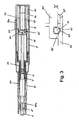
- Fig. 1 shows in longitudinal section an injection pen with an elongated, hollow cylindrical housing as a base part, which has a rear housing sleeve 4 with an internal thread in a front region and a front housing sleeve 7 with an external thread in a rear region.
- a container 1 is received, which is filled with an injectable product, in particular a medicament liquid.
- the container 1 is a conventional for such Injetationspens ampoule with a slidably received therein piston 2.
- a product dose from the container 1 is displaced.
- a pointing in the direction of the piston 2 injection needle N is attached, which is covered by a needle cap 3.
- the container 1 is received in a container holder 30 and centered.
- the container holder 30 is likewise formed by a sleeve which has three centering tabs 31 for centering the container 1 in a front region. Uniformly distributed over the circumference of the container holder 30 in the front region between the centering tabs 31 on the front ends protruding further tabs 32 are formed, which serve as a stop when pushing back a needle guard 10.
- an intermediate sleeve 20 is arranged in an annular gap between the container holder 30 and the front housing sleeve 7.
- the intermediate sleeve 20 is provided in its rear peripheral portion with recesses, which are penetrated by the container holder 30, which is so connected 29iebeêt with the front housing sleeve 7;
- the container holder 30 is screwed to the front housing sleeve 7.
- the intermediate sleeve 20, however, is displaceable relative to the front housing half 7 and the container holder 30 after releasing a lock 21 against the feed direction of the piston.
- a release sleeve 35 is arranged, which rests with a front end face on a rear end face of the intermediate sleeve 20.
- the release sleeve 35 is formed substantially simply hollow cylindrical and is penetrated by a projecting from the piston 2 to the rear piston rod. It is accommodated in the rear housing sleeve 4 in the longitudinal direction and herverschiebbar. From a return spring 9, it is pressed into its front position shown in Figure 1, in which it is flat on a rear End face of the intermediate sleeve 20 and a rear flange of the container 1 is present.
- a rear end face 36 of the release sleeve 30 drops obliquely outwards from a rear edge running around in an inner circumferential surface.
- the drive device is formed by a driven member 40 and a driven between the driven member 40 and the rear housing sleeve 4, serving as a drive element 49 drive spring.
- the output member 40 is cup-shaped with a rearwardly open sleeve body, formed by a simple circular cylindrical sleeve which protrudes from a closed sleeve bottom 41 to the rear. This sleeve body is seated in a surrounding inner sleeve 5 of the rear housing sleeve 4, which protrudes from a rear end wall of the rear housing sleeve 4 to the.
- the inner sleeve 5 forms a sliding guide for the output member 40. Further, it holds the output member 40 against the force of the drive member 49 with a plurality of uniformly distributed over its front peripheral portion, a front end face of the output member 40 embracing snap elements 6.
- Figure 1 shows the injection device in its initial position before an injection in which the output member 40 is blocked by means of the snap elements 6 and the needle N is surrounded by the needle guard 10.
- the needle N is surrounded by the needle guard 10, the needle is hidden in particular for a user of the injection device even when piercing the skin. This reduces a psychological inhibition to stab the needle N itself.
- a sleeve-shaped scraper 60 is also stored.
- the scraper 60 protrudes beyond a front end face of the needle guard 10 and is against a in the Needle protection sleeve 10 received restoring element 69, which is formed in the embodiment by a return spring, inserted into the needle guard 10.
- the scraper 60 serves for stripping a needle protection cap already removed in FIG. 1 and will be described later in relation to FIGS. 2a and 2b in its scraper function.
- the injection device is placed on the surface of a tissue, generally the human skin, and pressed against the tissue.
- a tissue generally the human skin
- the pressure of the scraper first 60 which forms the front end of the injection device, inserted against the force of the return element 69 in the needle guard 10 to a stop position in which it is wholly or almost completely taken up by the needle guard 10.
- the user releases the lock 21 by pressing a release button 8.
- the sliding blockage of the intermediate sleeve 20 relative to the front housing sleeve 7 is released.
- the needle guard 10 and under the pressure of the intermediate sleeve 20 and consequently the trigger sleeve 35 are moved in the housing to the rear.
- the needle N penetrates into the tissue.
- the inclined surface 36 of the trigger sleeve 35 comes into engagement with the snap elements. 6 and triggers the further retraction of the sleeves 10, 20 and 35, the fixation of the output member 40 at the moment in which the needle N has reached the desired, predetermined penetration depth.
- the output member 40 is advanced by the driving force of the drive member 49 in the feed direction, passes in pressure against a rear end face of the piston rod and pushes in their own further advancing the piston 2 in the container.
- the product from the container through the outlet and the adjoining needle is poured through.
- the entire container contents become distributed.
- the container content is the product dose in the embodiment. In principle, however, a plurality of prescribable product doses could only be distributed by several injections by constructive further development of the injection device.
- the driving force stored in the driving member is gradually consumed when using a driving spring as the driving member 49, for example, according to the spring characteristic.
- the feed rate of the piston 2 would therefore decrease in the course of advancing and drop the Aus sectionrate.
- a pneumatic damping force acting on the drive member 40 is generated.
- the chamber K is formed by the sleeve base 41 and the sleeve body of the output member 40 projecting therefrom on the one hand and the rear end face of the rear housing sleeve 4 and the inner sleeve 5 protruding therefrom on the other hand.
- the sleeve body of the output member 40 and the inner sleeve 5 are moved relative to each other like telescopic sleeves. In the area of the sliding surfaces, i.
- a circumferential sealing body 42 is arranged, sitting in the embodiment, a sealing ring in a circumferential groove of the sleeve body of the output member 40th
- the rear end surface of the rear housing sleeve 4 has a passage opening into which a sealing body 50 with a calibrated through-bore, but otherwise is used airtight.
- a check valve could be used, which allows unimpeded escape of air at a pushing back of the output member 40, but sucked against a valve seat during suction, leaving only a structurally given, defined, narrow passage opening.
- the volume flow introduced per unit time into the chamber K is up any case less than the per unit time with the advancement of the output member 40 associated volume increase of the chamber so that always a damping force is generated as long as the output member 40 is advanced by a resultant driving force.
- the damping force is greater, the faster the output member 40 is advanced, ie the greater the effective driving force is. Due to the nature of the damping force generation, an energy consumption occurring in the drive device is thus automatically compensated, since a decreasing drive force also accompanies a deceleration of the advancing movement of the drive member 40 and thus a reduction of the damping force. At the same time, however, irregularities in all other unavoidable counterforces are also compensated, since such irregularities are accompanied by delays or accelerations of the output member 40 and thus automatically changes in the volume change work to be performed by the drive element 49. Such counter forces are, for example, the wall friction between the container 1 and the piston 2, which is not the same everywhere over the feed path of the piston 2 in the container 1. The damping decreases due to the compressibility of the medium and the increase in the chamber volume in the course of advancing the output member 40 in addition, so that the energy consumption is compensated twice equal.
- FIGS. 2a and 2b show how a needle protection cap 3 can be removed with the aid of the scraper 60.
- the needle cap 3 is completely slipped over the injection needle. This corresponds to the state of the injection device immediately after insertion of the container 1 and the screwing together of the two housing sleeves 4 and 7. At the same time, this is the transport position of the injection device until shortly before an injection. To prepare for an injection, the needle cap 3 is first removed.
- FIG. 2a shows the initiation of the stripping of the needle protection cap 3.
- the sleeve-shaped scraper 60 is pushed against the pressure of the restoring element 69 into the needle protection sleeve 10 until it comes into contact with the needle protection cap 3 with two diametrically opposite engagement elements 61.
- the two engagement elements 61 protrude barb-like from a rear inner circumferential surface of the scraper 60 obliquely inward. When pushing back the scraper 60 they are increasingly pressed against the rearwardly widening needle cap 3.
- the scraper 60 can be released. He is pushed by the restoring element 69 back into its front position shown in Figure 2b against a stop shoulder 11 of the needle guard 10 and thereby strips the needle cap 3 from the container 1 from. In this position, the only loosely placed over the needle N needle cap 3 can be easily deducted by hand from the whole.
- the scraper 60 is provided with at least two tangible recesses 62.
- the scraper 60 is permanently attached to the injection device, the user does not need him awkward to pull off the needle cap 3. On the other hand, it does not interfere with the injection itself in any way.
- Another advantage is that the needle guard 10 is completely closed, i. without a penetration slot for stripping the needle cap 3, be formed and thereby the needle N can completely obscure.
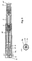
- FIG. 3 shows an autoinjection device with which not only the release of the product, but also the piercing of the needle takes place automatically.
- the same reference numerals are used as in the first embodiment, it is components of the same function.
- the basic mode of operation of the autoinjection device is concerned, reference is hereby made to the applicant's parallel German patent application of the same date entitled "Autoinjection Device”.
- a damping of the force acting on the output member 40 driving force in the autoinjection device of Figure 3 by means of mechanical friction acts between a pressure element designed as a resilient ring 45, which is clamped between the sleeve-shaped output member 40 and a surrounding the output member 40 during advancement, also sleeve-shaped transmission member 46.
- the sequence of an injection is in the autoinjector of Figure 3 is essentially the following:
- a trigger tab 8 By pressing a trigger tab 8, a feed movement of the output member 40 blocking barrier is released, and the output member 40 is the driving force of the drive member 49, which also in this embodiment Compression spring is, forward, in Figure 3 to the left, pushed.
- the pressure element 45 forms a coupling between the output member 40 and the transmission member 46, as can be seen in particular in the detailed representation X.
- this coupling takes the output member 40, the transmission member 46, which in turn advances the container 1 with the attached thereto at the front end needle N the housing opposite.
- the needle N from the housing in this embodiment fixed needle protective sleeve 10a is pushed and stabbed.
- the piercing is limited by striking the container holder 30 on the housing.
- When striking the coupling between the output member 40 and the transmission member 46 is released, as is apparent from the representation of the detail X easily.
- In its further advancing the output member 40 is now advanced relative to the transfer member 46, comes in contact pressure against the piston rod and pushes in his further advancing the piston 2 in the container 1, so that the product is distributed.
- the pressure element 45 is formed as a slotted spring ring in the manner of a piston ring. This ring is received in a circumferential groove on an outer periphery of the output member 40 and elastically presses against an inner Mantelgleit Chemistry the transfer member 46. By this inner Mantelgleit Chemistry is formed widening in the feed direction, acting between the pressure element 45 and the transfer member 46 wall friction force increases Course of advancing the output member 40 from. As a result, the release of the driving force of the drive element 49 is compensated.
- a guide ring 47 is placed, which serves as a straight guide for the output member 40.
- This guide ring 47 could also be used as a sealing ring with one or more calibrated through holes or a Check valve according to the embodiment of Figure 1 may be formed. In this way, instead of the frictional damping force or in addition to a pneumatic damping force could be generated.
- the vacuum chamber would be formed in such a formation in the gap region between the transmission member 46 and the inserting drive member 40.
- a holding and release sleeve 4b accommodated displaceably in the housing and, together with it, the output member 10, which are correspondingly connected to one another, are brought back into their rear position or tensioned.
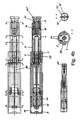
- Figures 4a and 4b show another autoinjection device in which, unlike the autoinjection device of Figure 3, the advancement of the container 1 for piercing the needle takes place in a conventional manner via the piston 2, i. the advance of the container 1 is not decoupled from the advancement of the piston 2, but takes place just above the piston 2.
- the injection device of Figures 4a and 4b like that of Figure 1, a needle protective sleeve 10 which can be moved back and forth relative to the housing.
- This slidable needle guard 10 which is not possible with the autoinjector of Figure 3, obscures the needle after injection, i. after pulling out.
- a scraper 65 is provided which is not permanently connected to the injection device, but must be inserted to strip the needle cap 3 between the needle cap 3 and the needle guard 10 until it engages behind the needle cap 3 like a claw that it can be removed together with the scraper 65.
- Figure 4a shows the injection device after an injection after pulling out the needle and already reassigned needle cap 3 for further transport.
- the special feature of this embodiment is a blocking of the needle protection sleeve 10.
- the needle guard 10 is blocked by a blocking element 80 to the housing opposite, such that the needle guard 10 can not be pushed against the feed direction of the needle N during insertion.
- the blocking element 80 is formed by a partial ring which has two engagement elements 81 in the form of two webs which protrude from an inner annular lateral surface.
- the needle guard 10 as best seen in Figure 4b lower left, two slots 15 which are penetrated by one of the engagement elements 81 when the locking member 80 is placed on the housing.
- the locking elements 80 is obtained by cutting a sleeve, in the embodiment of a circular sleeve, wherein the cutting takes place in the longitudinal direction and outside the central longitudinal axis of the sleeve, so that the blocking element 80th a shell body, seen in cross-section, protrudes a little beyond the semicircle and in this way, as will be explained with reference to Figure 4b, attachable via the rear housing sleeve 4 and the circumference is a piece over the largest diameter also held encompassing.
- the locking element 80 In its function as a lock for the needle guard 10, the locking element 80, as best seen in the cross sections B-B and C-C of Figure 4a, held by means of latching connection to the needle guard 10.
- the engagement elements 81 are elastically yielding and provided with front locking lugs which engage around one of the inner slot edges after penetration of the respective slot 15 and hold the locking element 80 as snapper in its blocking position, but can still easily be withdrawn.
- Figure 4b shows the blocking element 80 in its second function, in which it blocks the container 1 against advancement.
- the blocking element 80 is plugged in the transport position of the injection device until after removing the needle cap 3 in a the rear edge of the container 1 overlapping region of the housing.
- the shell body of the blocking element 80 surrounds the housing and is held on the rear housing sleeve 4 because of its ends projecting beyond the semicircle.
- the engagement elements 81 take over no holding function for the locking element 80, but now serve to block the container 1. For this they pass through the housing and come in the mounted state of the locking element 80 to lie at the rear end of the container 1 circumferential flange. Since the container 1 presses with its rear, radially outwardly projecting flange at a removal of the needle cap 3 on the engagement elements 81 of the locking member 80, the container 1 is blocked in its rear position and therefore can not be pulled forward.
- the blocking element 80 fulfills a further, third function in the position shown in FIG. 4 b, since it prevents a triggering of the drive device, simply by blocking the movement of a triggering means 70.
- the triggering means 70 can then release the output member 40 from its blocking when the blocking element 80 is removed from the housing and thus a forwarding of the trigger element 70 to the housing opposite only possible.
- FIG. 5 shows an autoinjection device which, with the exception of the triggering means 70 for the output member 40, corresponds to the injection device of FIGS. 4a and 4b.
- a trigger 70a of Figure 5 again consists of a sleeve body with a rear sleeve bottom. The output member 40 is blocked by the tripping means 70a both in its rearward position and disengaged after appropriate actuation of the tripping means 70a.
- the output member 40 extends to its rear end in snappers, which protrude through a rear housing end wall and engage around the rear peripheral edge, the latches of the output member 40 are pressed due to their own elasticity to the outside and already held.
- the triggering means 70a projects with a blocking piece 71 rising from its sleeve base, which has a narrow rectangle shape in cross-section and engages with its long side between two diametrically opposed latches of the driven member 40. It prevents in this rotational position that the two snapper can bend in the position shown in Figure 5 of the triggering means 70a to each other and so the locking connection would be solved.
- two pressing pieces 72 project from the sleeve bottom of the triggering means 70a and have the shape of partial circle segments in cross section.
- the blocking piece 71 projects beyond the pressing pieces 72.
- the blocking element 80 can also be designed as a rotary element and could thus remain in particular on the housing after the blocking of the container has been released.
- Figures 6a, 6b and 6c show the operation of the needle guard, which prevents the needle N after being pulled out of the tissue protrudes freely from the housing and can be broken off and cause injury in careless handling.
- the essential feature of the needle protection device is that for the purpose of puncturing the housing against sliding needle protective sleeve 10 is blocked after pulling out the needle in a needle protection position, so that they can not be pushed into the housing; an outside sliding over of the housing would also be conceivable.
- the operation of the pen for piercing the needle N and for dispensing the product corresponds to that of the pen of FIG. 3.
- Fig. 6a shows the front part of the pen in its initial position immediately before the injection.
- Fig. 6b shows the pen in the forward position of the container B, i. in the injection position.
- the needle guard 10 has been pressed against the force of the return element 19 in their rearmost sliding position of the housing sleeve 7 against.
- the needle N protrudes by the desired length from the housing and the needle guard 10 before.
- the needle guard 10 has a rear stop surface and a front stop surface, which limit the displacement of the needle guard 10 relative to the front housing sleeve 7 in the feed direction and against the feed direction.
- the needle protection sleeve 10 has, in an inner jacket region, with which it slides over the hook 82, approximately corresponding to the length of its maximum displacement, a broadening, preferably a slightly widened inner diameter.
- a transition region 14 from the widening to the adjoining inner cross section is bevelled, so that the needle protection sleeve 10 can slide under the pressure of the return element 19 beyond the transition region 14 via the hook 82.
- the needle protection sleeve 10 is provided behind the transition region 14 in a central region with longitudinal slots 15, the front end faces 16, as best seen in Fig. 6c, stop surfaces for each one of the hooks 82 form.
- the locking sleeve 80 terminates in a plurality of evenly distributed over the sleeve circumference arranged elastic resilient tongues 83, at the free front ends of each one of the hooks 82 are formed.
- the container holder 30 runs out to its free front end also in tongues 33.
- Each of the tongues 83 is thus supported radially inwardly and can not be bent radially inwardly in the front container position.
- the tongues 83 are not only supported by the tongues 33, but additionally pressed radially outward.
- the tongues 33 are rigid compared to the tongues 83 or, as a first approximation, these tongues 83 can be assumed to be rigid.
- the needle guard 10 After pulling out the needle N, the needle guard 10 is pushed by the return element 19 back to the front. Due to the oblique course of the surface 14 and / or the corresponding oblique course of the at least one hook 82, it overrides this hook 82, whose outgoing tip is also elastically yielding. However, as soon as the needle guard 10 has been advanced so far that their stop surface 16 seen in the feed direction comes to rest in front of the hooks 82, it is locked by the against the stop surface 16 on stop hook 82 against pushing back. The hook 82 and the needle guard 10 lie with perpendicular to the direction of facing stop surfaces together. The needle N is protected in the safety position shown in Figure 6c after injection through the needle guard 10.
- the container holder 30 is thus simultaneously used as a displaceable support for the at least one resilient blocking means 82 and fulfills the invention the double function of holding the container 1 and the blocking of the needle protection sleeve 10.
- the needle protection device does not require the inventive design of the autoinjection device, although they particularly preferably used in combination therewith. It is also usable with advantage in generic autoinjection devices.
Landscapes
- Health & Medical Sciences (AREA)
- Animal Behavior & Ethology (AREA)
- Public Health (AREA)
- Anesthesiology (AREA)
- Biomedical Technology (AREA)
- Heart & Thoracic Surgery (AREA)
- Hematology (AREA)
- Engineering & Computer Science (AREA)
- Life Sciences & Earth Sciences (AREA)
- General Health & Medical Sciences (AREA)
- Vascular Medicine (AREA)
- Veterinary Medicine (AREA)
- Infusion, Injection, And Reservoir Apparatuses (AREA)
- Acyclic And Carbocyclic Compounds In Medicinal Compositions (AREA)
- Medicinal Preparation (AREA)
- External Artificial Organs (AREA)
- Medical Preparation Storing Or Oral Administration Devices (AREA)
Claims (14)
- Dispositif d'administration d'un produit injectable, comprenant au moins :a) un élément de base (4, 7),b) un récipient (1) logé dans l'élément de base (4, 7) et à partir duquel, en déplaçant dans un sens d'avance un piston (2) qui y est logé, une dose de produit est déversée à travers une aiguille (N) etc) un dispositif d'entraînement comprenant au moins un élément de sortie (40) et un élément d'entraînement (49) qui exerce sur l'élément de sortie (40), lorsque le dispositif d'entraînement est actionné, une force d'entraînement grâce à laquelle l'élément de sortie (40) est déplacé dans le sens d'avance du piston (2) en faisant avancer le piston (2) dans le récipient (1),d) caractérisé en ce que, pour enlever un capuchon de protection d'aiguille (3) emboîté sur l'aiguille (N), un dispositif d'enlèvement (60) est placé sur le dispositif dans le sens longitudinal de l'aiguille (N) de manière à pouvoir être déplacé dans les deux sens, de telle manière que le dispositif d'enlèvement (60) puisse rester sur le dispositif pendant une injection et soit repoussé pour enfoncer l'aiguille (N).
- Dispositif selon la revendication 1, caractérisé en ce que le dispositif d'enlèvement (60) est doté de moyens de prise (61) pour bloquer ou agripper le capuchon de protection d'aiguille (3).
- Dispositif selon la revendication précédente, caractérisé en ce que les moyens de prise (61) sont disposés diamétralement opposés les uns par rapport aux autres et dépassent obliquement vers l'intérieur à partir d'une surface d'enveloppe arrière intérieure du dispositif d'enlèvement (60) à la manière d'ardillons.
- Dispositif selon une des deux revendications précédentes, caractérisé en ce qu'une douille de protection d'aiguille (10) est disposée de manière à pouvoir être déplacée par rapport à l'élément de base (4, 7) depuis une position initiale dans laquelle elle entoure l'aiguille (N) jusqu'au-delà de la pointe de l'aiguille jusque dans une position d'administration dans laquelle l'aiguille (N) dépasse de la douille de protection d'aiguille (10) et en ce que la douille de protection d'aiguille (10) peut être bloquée par rapport à l'élément de base (4, 7) à l'encontre d'un déplacement en direction de la position d'administration.
- Dispositif selon la revendication précédente, caractérisé en ce que le dispositif d'enlèvement (60) est logé dans la douille de protection d'aiguille (10).
- Dispositif selon la revendication précédente, caractérisé en ce que le dispositif d'enlèvement (60) peut être inséré dans la douille de protection d'aiguille (10) contre un élément de rappel (69).
- Dispositif selon une des revendications précédentes, caractérisé en ce que le dispositif est un appareil d'injection automatique, en ce que le récipient (1) avec l'aiguille (N) placée dessus peut être avancé depuis une position initiale jusque dans une position d'administration par rapport à l'élément de base (4, 7) pour enfoncer l'aiguille (N) et en ce que le récipient (1) est bloqué en position initiale à l'encontre d'un déplacement par prise amovible d'un moyen de blocage (80, 82).
- Dispositif selon la revendication 4 ou 7, caractérisé en ce que le moyen de blocage (80) bloque au choix soit le récipient (1) contre une avance, soit la douille de protection d'aiguille (10) contre un recul.
- Dispositif selon une des revendications précédentes, caractérisé en ce que sont prévus des moyens (42, 50 ; 45, 46) qui génèrent une force d'amortissement qui agit en sens contraire de la force d'entraînement pendant une avance du piston (2) en plus de toutes les forces antagonistes non évitables.
- Dispositif selon la revendication précédente, caractérisé en ce que la force d'amortissement diminue pendant le déplacement du piston.
- Dispositif selon la revendication 9 ou 10, caractérisé en ce que l'élément de sortie (40) forme au moins une paroi d'un compartiment (K) qui comporte au moins un orifice de compartiment pour un fluide qui afflue dans le compartiment (K) ou s'écoule hors du compartiment (K), l'orifice du compartiment ne permettant qu'avec un décalage une compensation de pression lors d'une avance de l'élément de sortie (40) et d'une modification de volume du compartiment (K) qui y est associée.
- Dispositif selon la revendication précédente, caractérisé en ce que le compartiment (K) est un compartiment en dépression.
- Dispositif selon la revendication 9 ou 10, caractérisé en ce que, pour générer la force d'amortissement, il est prévu un élément de pression (45) qui transmet une force de blocage entre l'élément de sortie (40) et un contre-élément (46), l'élément de sortie (40) ou le contre-élément (46) comportant pour le moyen de pression (45) une surface de pression qui s'étend dans le sens d'avance de l'élément de sortie (40) de telle manière que la force de blocage diminue pendant l'avance.
- Dispositif selon une des revendications précédentes, caractérisé en ce que l'élément de pression (45) est un anneau souple qui est disposé dans une fente formée entre l'élément d'entraînement (40) et le contre-élément (46) et s'élargit pendant l'avance de l'élément de sortie (40).
Priority Applications (2)
| Application Number | Priority Date | Filing Date | Title |
|---|---|---|---|
| EP06024785A EP1762261B1 (fr) | 1998-05-15 | 1999-05-07 | Dispositif d'administration d'un produit injectable |
| ES06024785T ES2306347T3 (es) | 1998-05-15 | 1999-05-07 | Dispositivo para administrar un producto inyectable. |
Applications Claiming Priority (3)
| Application Number | Priority Date | Filing Date | Title |
|---|---|---|---|
| DE19821933A DE19821933C1 (de) | 1998-05-15 | 1998-05-15 | Vorrichtung zur Verabreichung eines injizierbaren Produkts |
| DE19821933 | 1998-05-15 | ||
| EP99810406A EP0956875B1 (fr) | 1998-05-15 | 1999-05-07 | Dispositif pour l'application dosée d'un produit injectable |
Related Parent Applications (2)
| Application Number | Title | Priority Date | Filing Date |
|---|---|---|---|
| EP99810406.1 Division | 1999-05-07 | ||
| EP99810406A Division EP0956875B1 (fr) | 1998-05-15 | 1999-05-07 | Dispositif pour l'application dosée d'un produit injectable |
Related Child Applications (1)
| Application Number | Title | Priority Date | Filing Date |
|---|---|---|---|
| EP06024785A Division EP1762261B1 (fr) | 1998-05-15 | 1999-05-07 | Dispositif d'administration d'un produit injectable |
Publications (3)
| Publication Number | Publication Date |
|---|---|
| EP1586342A2 EP1586342A2 (fr) | 2005-10-19 |
| EP1586342A3 EP1586342A3 (fr) | 2006-04-05 |
| EP1586342B1 true EP1586342B1 (fr) | 2007-01-03 |
Family
ID=7867947
Family Applications (4)
| Application Number | Title | Priority Date | Filing Date |
|---|---|---|---|
| EP05015620A Expired - Lifetime EP1586342B1 (fr) | 1998-05-15 | 1999-05-07 | Dispositif d'administration d'un produit injectable |
| EP05015619A Expired - Lifetime EP1586341B1 (fr) | 1998-05-15 | 1999-05-07 | Dispositif pour l'application dosée d'un produit injectable |
| EP99810406A Expired - Lifetime EP0956875B1 (fr) | 1998-05-15 | 1999-05-07 | Dispositif pour l'application dosée d'un produit injectable |
| EP06024785A Expired - Lifetime EP1762261B1 (fr) | 1998-05-15 | 1999-05-07 | Dispositif d'administration d'un produit injectable |
Family Applications After (3)
| Application Number | Title | Priority Date | Filing Date |
|---|---|---|---|
| EP05015619A Expired - Lifetime EP1586341B1 (fr) | 1998-05-15 | 1999-05-07 | Dispositif pour l'application dosée d'un produit injectable |
| EP99810406A Expired - Lifetime EP0956875B1 (fr) | 1998-05-15 | 1999-05-07 | Dispositif pour l'application dosée d'un produit injectable |
| EP06024785A Expired - Lifetime EP1762261B1 (fr) | 1998-05-15 | 1999-05-07 | Dispositif d'administration d'un produit injectable |
Country Status (7)
| Country | Link |
|---|---|
| US (5) | US6258068B1 (fr) |
| EP (4) | EP1586342B1 (fr) |
| JP (1) | JP4436482B2 (fr) |
| AT (4) | ATE392912T1 (fr) |
| DE (5) | DE19821933C1 (fr) |
| DK (2) | DK0956875T3 (fr) |
| ES (2) | ES2248974T3 (fr) |
Cited By (2)
| Publication number | Priority date | Publication date | Assignee | Title |
|---|---|---|---|---|
| US10722655B2 (en) | 2014-05-07 | 2020-07-28 | Amgen Inc. | Autoinjector with shock reducing elements |
| US11904143B2 (en) | 2017-06-08 | 2024-02-20 | Amgen Inc. | Torque driven drug delivery device |
Families Citing this family (160)
| Publication number | Priority date | Publication date | Assignee | Title |
|---|---|---|---|---|
| DE19821933C1 (de) * | 1998-05-15 | 1999-11-11 | Disetronic Licensing Ag | Vorrichtung zur Verabreichung eines injizierbaren Produkts |
| US7063684B2 (en) * | 1999-10-28 | 2006-06-20 | Medtronic Minimed, Inc. | Drive system seal |
| US20020077270A1 (en) * | 2000-01-31 | 2002-06-20 | Rosen Craig A. | Nucleic acids, proteins, and antibodies |
| GB0003790D0 (en) | 2000-02-18 | 2000-04-05 | Astrazeneca Uk Ltd | Medical device |
| GB0118419D0 (en) | 2001-07-28 | 2001-09-19 | Owen Mumford Ltd | Improvements relating to injection devices |
| CN100444908C (zh) * | 2002-05-02 | 2008-12-24 | Pa咨询服务有限公司 | 注射装置 |
| US7141036B2 (en) * | 2002-06-04 | 2006-11-28 | Syringe, Llc | Methods of applying a medicinal substance |
| US7125394B2 (en) * | 2002-06-04 | 2006-10-24 | Syringe, Llc | Applicator for dispensing a medicinal substance |
| SG121744A1 (en) | 2002-11-06 | 2006-05-26 | Becton Dickinson Co | Flashback blood collection needle with needle shield |
| EP1588370A1 (fr) * | 2003-01-13 | 2005-10-26 | Koninklijke Philips Electronics N.V. | Navigation vers un contenu dans un enregistrement |
| US20040143226A1 (en) * | 2003-01-16 | 2004-07-22 | Becton, Dickinson And Company | Blood collection set with venting mechanism |
| DE10320225A1 (de) * | 2003-05-05 | 2004-12-02 | L + N Plast-Vertriebs Gmbh | Mehrweg-Betätigungsvorrichtung für eine sterile Spritze |
| DE10339794A1 (de) * | 2003-08-28 | 2005-04-07 | Tecpharma Licensing Ag | Verabreichungsvorrichtung mit einer Schutzkappenabziehvorrichtung und einer Nadelschutzhülsenblockiereinrichtung |
| DE10340586A1 (de) * | 2003-09-03 | 2005-04-07 | Tecpharma Licensing Ag | Abmischvorrichtung für Mehrkammerampulle |
| DE10342059B4 (de) * | 2003-09-11 | 2007-03-01 | Tecpharma Licensing Ag | Verabreichungsvorrichtung mit Einstech- und Ausschütteinrichtung |
| IL157981A (en) | 2003-09-17 | 2014-01-30 | Elcam Medical Agricultural Cooperative Ass Ltd | Auto injector |
| US20050085776A1 (en) * | 2003-10-16 | 2005-04-21 | Edgar Hommann | Injection device for administering a fluid product |
| DE10351599A1 (de) * | 2003-11-05 | 2005-06-16 | Tecpharma Licensing Ag | Autoinjektionsvorrichtung |
| CH696421A5 (de) | 2003-12-18 | 2007-06-15 | Tecpharma Licensing Ag | Autoinjektor mit Arretierung des Wirkstoffbehälters. |
| GB2414401B (en) | 2004-05-28 | 2009-06-17 | Cilag Ag Int | Injection device |
| GB2414775B (en) | 2004-05-28 | 2008-05-21 | Cilag Ag Int | Releasable coupling and injection device |
| GB2414404B (en) | 2004-05-28 | 2009-06-03 | Cilag Ag Int | Injection device |
| GB2414399B (en) | 2004-05-28 | 2008-12-31 | Cilag Ag Int | Injection device |
| GB2414402B (en) | 2004-05-28 | 2009-04-22 | Cilag Ag Int | Injection device |
| GB2414406B (en) | 2004-05-28 | 2009-03-18 | Cilag Ag Int | Injection device |
| GB2414409B (en) | 2004-05-28 | 2009-11-18 | Cilag Ag Int | Injection device |
| GB2414405B (en) * | 2004-05-28 | 2009-01-14 | Cilag Ag Int | Injection device |
| GB2414403B (en) | 2004-05-28 | 2009-01-07 | Cilag Ag Int | Injection device |
| GB2414400B (en) | 2004-05-28 | 2009-01-14 | Cilag Ag Int | Injection device |
| GB0414054D0 (en) | 2004-06-23 | 2004-07-28 | Owen Mumford Ltd | Improvements relating to automatic injection devices |
| US7449012B2 (en) | 2004-08-06 | 2008-11-11 | Meridian Medical Technologies, Inc. | Automatic injector |
| US8048035B2 (en) | 2004-08-06 | 2011-11-01 | Meridian Medical Technologies, Inc. | Automatic injector with needle cover |
| US7648483B2 (en) | 2004-11-22 | 2010-01-19 | Intelliject, Inc. | Devices, systems and methods for medicament delivery |
| US7648482B2 (en) | 2004-11-22 | 2010-01-19 | Intelliject, Inc. | Devices, systems, and methods for medicament delivery |
| US10737028B2 (en) | 2004-11-22 | 2020-08-11 | Kaleo, Inc. | Devices, systems and methods for medicament delivery |
| US7947017B2 (en) | 2004-11-22 | 2011-05-24 | Intelliject, Inc. | Devices, systems and methods for medicament delivery |
| US11590286B2 (en) | 2004-11-22 | 2023-02-28 | Kaleo, Inc. | Devices, systems and methods for medicament delivery |
| CA2586525C (fr) | 2004-11-22 | 2013-01-15 | Intelliject, Llc | Dispositifs, systemes et procedes d'administration de medicaments |
| CN101111281B (zh) | 2005-02-01 | 2013-02-06 | 因特利杰克特有限公司 | 用于药物递送的设备、系统和方法 |
| DE102005007614A1 (de) * | 2005-02-18 | 2006-08-24 | Tecpharma Licensing Ag | Autoinjektor mit einer Auslöseverriegelung |
| GB2424836B (en) | 2005-04-06 | 2010-09-22 | Cilag Ag Int | Injection device (bayonet cap removal) |
| GB2427826B (en) | 2005-04-06 | 2010-08-25 | Cilag Ag Int | Injection device comprising a locking mechanism associated with integrally formed biasing means |
| GB2424835B (en) | 2005-04-06 | 2010-06-09 | Cilag Ag Int | Injection device (modified trigger) |
| GB2424838B (en) | 2005-04-06 | 2011-02-23 | Cilag Ag Int | Injection device (adaptable drive) |
| GB2425062B (en) | 2005-04-06 | 2010-07-21 | Cilag Ag Int | Injection device |
| DE102005038933A1 (de) * | 2005-08-17 | 2007-02-22 | L + N Plast Vertriebs Gmbh | Autoinjektionsgerät |
| ES2340936T3 (es) | 2005-08-30 | 2010-06-11 | Cilag Gmbh International | Montaje de aguja para un sistema de jeringa precargada. |
| US20110098656A1 (en) | 2005-09-27 | 2011-04-28 | Burnell Rosie L | Auto-injection device with needle protecting cap having outer and inner sleeves |
| EP1937334B1 (fr) | 2005-12-07 | 2009-09-02 | Painless Tech GmbH | Dispositif d'injection et unite ampoule |
| GB0601309D0 (en) | 2006-01-23 | 2006-03-01 | Medical House The Plc | Injection device |
| US20070173770A1 (en) | 2006-01-23 | 2007-07-26 | The Medical House Plc | Injection device |
| GB2438593B (en) | 2006-06-01 | 2011-03-30 | Cilag Gmbh Int | Injection device (cap removal feature) |
| GB2438590B (en) | 2006-06-01 | 2011-02-09 | Cilag Gmbh Int | Injection device |
| GB2438591B (en) | 2006-06-01 | 2011-07-13 | Cilag Gmbh Int | Injection device |
| CN103316402A (zh) | 2006-06-30 | 2013-09-25 | 艾伯维生物技术有限公司 | 自动注射装置 |
| FR2905273B1 (fr) | 2006-09-06 | 2009-04-03 | Becton Dickinson France Soc Pa | Dispositif d'injection automatique avec moyen de temporisation. |
| GB0618294D0 (en) * | 2006-09-19 | 2006-10-25 | Cambridge Biostability Ltd | An injector |
| WO2008047372A2 (fr) * | 2006-10-19 | 2008-04-24 | Elcam Medical Agricultural Cooperative Association Ltd. | Dispositif d'injection automatique |
| DK2099434T3 (da) | 2006-11-21 | 2019-08-12 | Kaleo Inc | Indretninger og systemer til medikamentindgivelse |
| DK1932558T3 (da) * | 2006-12-13 | 2011-09-05 | Shl Group Ab | Autoinjektor |
| MX2009009494A (es) * | 2007-03-09 | 2009-09-15 | Lilly Co Eli | Mecanismo de retardo para dispositivo de inyeccion automatica. |
| US20080249477A1 (en) * | 2007-04-05 | 2008-10-09 | West Pharmaceutical Services, Inc. | Pen injector having a needle shield |
| DE102007030327A1 (de) | 2007-06-29 | 2009-01-02 | Tecpharma Licensing Ag | Injektionsvorrichtung mit einer Feder für eine Nadelschutzhülse |
| DE102007031714A1 (de) * | 2007-07-06 | 2009-01-08 | Lts Lohmann Therapie-Systeme Ag | Einweginjektor mit mindestens einem Druckstab und einer Verschlusskappe |
| DE102007031630B3 (de) * | 2007-07-06 | 2008-12-24 | Lts Lohmann Therapie-Systeme Ag | Einweginjektor mit mindestens einem Stützstab |
| DE102007032464A1 (de) * | 2007-07-10 | 2009-01-15 | Lts Lohmann Therapie-Systeme Ag | Einweginjektor mit mindestens einem Zughaken |
| DE102007032463A1 (de) * | 2007-07-10 | 2009-01-15 | Lts Lohmann Therapie-Systeme Ag | Einweginjektor mit mindestens einem zwangsentkoppelbaren Zughaken |
| DE102007034871A1 (de) * | 2007-07-24 | 2009-01-29 | Lts Lohmann Therapie-Systeme Ag | Einweginjektor mit handbetätigbarem Kolben |
| GB2451665B (en) * | 2007-08-08 | 2012-09-26 | Cilag Gmbh Int | Injection device |
| EP2211943B1 (fr) * | 2007-10-10 | 2016-12-21 | SHL Group AB | Dispositif de distribution médical |
| DE102008011310A1 (de) * | 2008-02-27 | 2009-09-10 | Painless Tech Gmbh | Injektionsvorrichtung zur nadelfreien Injektion eines Mediums |
| WO2009065835A1 (fr) | 2007-11-19 | 2009-05-28 | Painless Tech Gmbh | Dispositif d'injection pour injecter un fluide sans aiguille |
| DE102008011881A1 (de) * | 2008-02-29 | 2009-09-10 | Tecpharma Licensing Ag | Leerschießgeschwindigkeitsbegrenzungsbremse |
| GB2461086B (en) | 2008-06-19 | 2012-12-05 | Cilag Gmbh Int | Injection device |
| GB2461089B (en) | 2008-06-19 | 2012-09-19 | Cilag Gmbh Int | Injection device |
| GB2461088B (en) * | 2008-06-19 | 2012-09-26 | Cilag Gmbh Int | Injection device |
| GB2461087B (en) | 2008-06-19 | 2012-09-26 | Cilag Gmbh Int | Injection device |
| GB2461084B (en) | 2008-06-19 | 2012-09-26 | Cilag Gmbh Int | Fluid transfer assembly |
| GB2461085B (en) | 2008-06-19 | 2012-08-29 | Cilag Gmbh Int | Injection device |
| DE102008037310B4 (de) | 2008-08-11 | 2023-11-16 | Ypsomed Ag | Automatische Injektionsvorrichtung für die Verabreichung einer festen Dosis |
| DE102008064985B4 (de) * | 2008-08-11 | 2025-12-31 | Ypsomed Ag | Automatische Injektionsvorrichtung für die Verabreichung einer festen Dosis |
| ES2963068T3 (es) | 2008-09-29 | 2024-03-25 | Becton Dickinson France | Dispositivo de inyección con medios de retención accionados por protector de aguja |
| GB0900930D0 (en) | 2009-01-20 | 2009-03-04 | Future Injection Technologies Ltd | Injection device |
| DE102009008754A1 (de) * | 2009-02-12 | 2010-08-26 | Tecpharma Licensing Ag | Verabreichungsvorrichtung, insbesondere Autoinjektionsvorrichtung, für eine medizinische Substanz mit einer Abzugshilfe für eine Schutzkappe |
| US8118808B2 (en) * | 2009-03-10 | 2012-02-21 | Vivant Medical, Inc. | Cooled dielectrically buffered microwave dipole antenna |
| US8864725B2 (en) | 2009-03-17 | 2014-10-21 | Baxter Corporation Englewood | Hazardous drug handling system, apparatus and method |
| CN102458517B (zh) | 2009-04-29 | 2014-07-23 | 阿布维生物技术有限公司 | 自动注射装置 |
| WO2010136076A1 (fr) * | 2009-05-29 | 2010-12-02 | Tecpharma Licensing Ag | Dispositif d'injection comprenant un système destiné à séparer un capuchon de protection d'aiguille d'un réservoir à produit |
| GB2471473A (en) * | 2009-06-30 | 2011-01-05 | Owen Mumford Ltd | Syringe sheath remover |
| KR101131577B1 (ko) * | 2009-07-22 | 2012-03-30 | 방시열 | 피부 시술 장치 |
| US9526846B2 (en) | 2009-08-19 | 2016-12-27 | Safety Syringes, Inc. | Patient-contact activated needle stick safety device |
| WO2011032731A1 (fr) * | 2009-09-21 | 2011-03-24 | Tecpharma Licensing Ag | Amortissement d'une tige de piston pour seringues partiellement remplies |
| NZ600069A (en) | 2009-12-15 | 2015-02-27 | Abbvie Biotechnology Ltd | Improved firing button for automatic injection device |
| EP2515973B1 (fr) | 2009-12-23 | 2018-02-21 | Tecpharma Licensing AG | Dispositif d'injection comportant une gaine de protection d'aiguille |
| WO2011076281A1 (fr) | 2009-12-23 | 2011-06-30 | Tecpharma Licensing Ag | Dispositif pour retirer un capuchon de protection d'aiguille d'une aiguille |
| US20130060201A1 (en) * | 2010-03-01 | 2013-03-07 | Sergey Popov | Puncturing device with a needle shield and a method for needle shield removal |
| PT2542280E (pt) | 2010-03-01 | 2014-09-12 | Lilly Co Eli | Dispositivo automático de injecção com mecanismo de atraso que inclui um membro de pressionar de dupla função |
| GB2478349A (en) * | 2010-03-05 | 2011-09-07 | Owen Mumford Ltd | Injection device having projections reducing the diameter of the syringe passage |
| NZ702172A (en) | 2010-04-21 | 2016-03-31 | Abbvie Biotechnology Ltd | Wearable automatic injection device for controlled delivery of therapeutic agents |
| EP2399631A1 (fr) | 2010-06-28 | 2011-12-28 | Sanofi-Aventis Deutschland GmbH | Auto-injecteur avec élément d'amortissement d'injection |
| AU2011290668B2 (en) | 2010-08-19 | 2014-08-14 | Novo Nordisk A/S | Medical auto-injection device for manual needle insertion having needle shield, damping mechanism and audible and tactile feedback |
| WO2012045350A1 (fr) | 2010-10-06 | 2012-04-12 | Tecpharma Licensing Ag | Mécanisme de verrouillage et de retenue pour le protecteur d'aiguille d'un dispositif d'injection |
| GB2487235A (en) * | 2011-01-17 | 2012-07-18 | Owen Mumford Ltd | Injection device with pneumatic damping of the drive mechanism |
| EP3187216B1 (fr) | 2011-01-24 | 2019-08-21 | AbbVie Biotechnology Ltd. | Dispositifs d'injection automatique présentant des surfaces de préhension surmoulées |
| US8992477B2 (en) | 2011-01-24 | 2015-03-31 | Elcam Agricultural Cooperative Association Ltd. | Injector |
| AU2012209222B2 (en) | 2011-01-24 | 2015-07-09 | Abbvie Biotechnology Ltd | Removal of needle shields from syringes and automatic injection devices |
| US9173999B2 (en) | 2011-01-26 | 2015-11-03 | Kaleo, Inc. | Devices and methods for delivering medicaments from a multi-chamber container |
| US8939943B2 (en) | 2011-01-26 | 2015-01-27 | Kaleo, Inc. | Medicament delivery device for administration of opioid antagonists including formulations for naloxone |
| EP2702077A2 (fr) | 2011-04-27 | 2014-03-05 | AbbVie Inc. | Procédé de contrôle du profil de galactosylation de protéines exprimées de manière recombinante |
| EP2578189A1 (fr) * | 2011-10-07 | 2013-04-10 | Sanofi-Aventis Deutschland GmbH | Appareil pour injection intraoculaire |
| EP2926860B1 (fr) * | 2012-03-14 | 2018-12-26 | SHL Medical AG | Dispositifs d'administration de médicaments |
| DE102012204394A1 (de) * | 2012-03-20 | 2013-09-26 | B. Braun Melsungen Ag | Injektionsvorrichtung zur Verabreichung einer Flüssigkeit |
| US9067990B2 (en) | 2013-03-14 | 2015-06-30 | Abbvie, Inc. | Protein purification using displacement chromatography |
| US9181572B2 (en) | 2012-04-20 | 2015-11-10 | Abbvie, Inc. | Methods to modulate lysine variant distribution |
| US9334319B2 (en) | 2012-04-20 | 2016-05-10 | Abbvie Inc. | Low acidic species compositions |
| US9505833B2 (en) | 2012-04-20 | 2016-11-29 | Abbvie Inc. | Human antibodies that bind human TNF-alpha and methods of preparing the same |
| WO2013176754A1 (fr) | 2012-05-24 | 2013-11-28 | Abbvie Inc. | Nouvelle purification d'anticorps au moyen de chromatographie à interaction hydrophobe |
| US9512214B2 (en) | 2012-09-02 | 2016-12-06 | Abbvie, Inc. | Methods to control protein heterogeneity |
| HK1211981A1 (en) | 2012-09-02 | 2016-06-03 | Abbvie Inc. | Methods to control protein heterogeneity |
| EP2742963A1 (fr) * | 2012-12-17 | 2014-06-18 | Sanofi-Aventis Deutschland GmbH | Dispositif d'administration de médicaments |
| ES2927108T3 (es) | 2013-03-14 | 2022-11-02 | Lilly Co Eli | Mecanismo de retardo adecuado para dispositivo de inyección automática compacto |
| WO2014151878A2 (fr) | 2013-03-14 | 2014-09-25 | Abbvie Inc. | Procédés pour la modulation des profils de glycosylation de protéines de traitements à base de protéines recombinantes au moyen de monosaccharides et d'oligosaccharides |
| WO2014159579A1 (fr) | 2013-03-14 | 2014-10-02 | Abbvie Inc. | Anticorps anti-tnfα ayant mutés et leurs procédés d'utilisation |
| US9017687B1 (en) | 2013-10-18 | 2015-04-28 | Abbvie, Inc. | Low acidic species compositions and methods for producing and using the same using displacement chromatography |
| HUE033629T2 (en) | 2013-03-14 | 2017-12-28 | Lilly Co Eli | Release mechanism for automatic injection device |
| AR095807A1 (es) * | 2013-04-10 | 2015-11-11 | Sanofi Sa | Mecanismo de control de velocidad de dispensación y dispositivo de inyección |
| GB2515039B (en) | 2013-06-11 | 2015-05-27 | Cilag Gmbh Int | Injection Device |
| GB2515032A (en) | 2013-06-11 | 2014-12-17 | Cilag Gmbh Int | Guide for an injection device |
| GB2517896B (en) | 2013-06-11 | 2015-07-08 | Cilag Gmbh Int | Injection device |
| GB2515038A (en) | 2013-06-11 | 2014-12-17 | Cilag Gmbh Int | Injection device |
| PL3038682T3 (pl) | 2013-08-29 | 2019-04-30 | Sanofi Sa | Zatyczka na pojemnik medyczny |
| WO2015051293A2 (fr) | 2013-10-04 | 2015-04-09 | Abbvie, Inc. | Utilisation d'ions métalliques pour moduler les profils de glycosylation des protéines dans le cas de protéines recombinées |
| US8946395B1 (en) | 2013-10-18 | 2015-02-03 | Abbvie Inc. | Purification of proteins using hydrophobic interaction chromatography |
| US9085618B2 (en) | 2013-10-18 | 2015-07-21 | Abbvie, Inc. | Low acidic species compositions and methods for producing and using the same |
| US9181337B2 (en) | 2013-10-18 | 2015-11-10 | Abbvie, Inc. | Modulated lysine variant species compositions and methods for producing and using the same |
| EP2868338A1 (fr) | 2013-10-31 | 2015-05-06 | Sanofi-Aventis Deutschland GmbH | Dispositifs d'administration de médicaments |
| CA2929184A1 (fr) * | 2013-11-13 | 2015-05-21 | Genentech, Inc. | Dispositifs et procedes d'injection manuelle assistee |
| US20150139988A1 (en) | 2013-11-15 | 2015-05-21 | Abbvie, Inc. | Glycoengineered binding protein compositions |
| EP2878323A1 (fr) * | 2013-11-28 | 2015-06-03 | Sanofi-Aventis Deutschland GmbH | Dispositif d'administration de médicaments avec protecteur d'aiguille pourvue d'un enleveur d'un bouchon d'aiguille |
| JP6275291B2 (ja) * | 2014-03-12 | 2018-02-07 | ウェイ,ミン | 薬物自動注射器 |
| DE102014005338A1 (de) * | 2014-04-11 | 2015-10-15 | Andreas Gerzen | Injektionsvorrichtung zum kontinuierlichen und gleichmäßigen Applizieren einer Injektionssubstanz |
| US10376686B2 (en) | 2014-04-23 | 2019-08-13 | Becton, Dickinson And Company | Antimicrobial caps for medical connectors |
| US9517307B2 (en) | 2014-07-18 | 2016-12-13 | Kaleo, Inc. | Devices and methods for delivering opioid antagonists including formulations for naloxone |
| TW201705994A (zh) * | 2015-06-03 | 2017-02-16 | 賽諾菲阿凡提斯德意志有限公司 | 自動注射器及組裝方法 |
| EP4166170A1 (fr) | 2015-06-30 | 2023-04-19 | Kaleo, Inc. | Auto-injecteurs pour l'administration d'un médicament à l'intérieur d'une seringue préremplie |
| DE102015214087A1 (de) * | 2015-07-24 | 2017-01-26 | Vetter Pharma-Fertigung GmbH & Co. KG | Abzieheinrichtung und Verfahren zum Betreiben einer Abzieheinrichtung |
| WO2017089274A1 (fr) * | 2015-11-27 | 2017-06-01 | Sanofi-Aventis Deutschland Gmbh | Système de retrait de capuchon |
| US11058825B2 (en) | 2015-11-27 | 2021-07-13 | Sanofi-Aventis Deutschland Gmbh | Cap for an injection device |
| US10751476B2 (en) | 2016-06-09 | 2020-08-25 | Becton, Dickinson And Company | Actuator assembly for drug delivery system |
| US10792432B2 (en) | 2016-06-09 | 2020-10-06 | Becton, Dickinson And Company | Drive assembly and spacer for drug delivery system |
| US10603445B2 (en) | 2016-06-09 | 2020-03-31 | Becton, Dickinson And Company | Needle actuator assembly for drug delivery system |
| US10549044B2 (en) | 2016-06-09 | 2020-02-04 | Becton, Dickinson And Company | Spacer assembly for drug delivery system |
| CA3046228A1 (fr) | 2016-12-23 | 2018-06-28 | Kaleo, Inc. | Dispositif d'administration de medicament et procedes d'administration de medicaments a des nourrissons et des enfants |
| CA3079357C (fr) | 2017-10-16 | 2022-12-13 | Becton, Dickinson And Company | Ensemble d'ecartement pour dispositif d'administration de medicament |
| US12569620B2 (en) | 2018-01-19 | 2026-03-10 | Birya Biotech, Inc. | Tool for servicing an auto-injector |
| US11040142B2 (en) | 2018-03-12 | 2021-06-22 | E3D A.C.A.L Ltd | Automatic injection device with a dampening element |
| WO2020140040A1 (fr) | 2018-12-29 | 2020-07-02 | Kaleo, Inc. | Dispositifs et procédés de distribution de substances dans une seringue pré-remplie |
| AU2020331302B2 (en) | 2019-08-09 | 2025-09-25 | Kaleo, Inc. | Devices and methods for delivery of substances within a prefilled syringe |
| US12268847B1 (en) | 2021-02-10 | 2025-04-08 | Kaleo, Inc. | Devices and methods for delivery of substances within a medicament container |
| WO2022191135A1 (fr) * | 2021-03-12 | 2022-09-15 | テルモ株式会社 | Dispositif d'administration de liquide pharmaceutique |
Family Cites Families (83)
| Publication number | Priority date | Publication date | Assignee | Title |
|---|---|---|---|---|
| BE755224A (fr) | 1969-08-25 | 1971-02-24 | Philips Nv | Seringue d'injection |
| US4355351A (en) | 1979-05-30 | 1982-10-19 | Schwarz Francisc C | High repetition rate power pulse generator |
| DE3163728D1 (en) | 1980-04-08 | 1984-06-28 | Greater Glasgow Health Board | Dispensing device |
| GB2109690B (en) | 1981-02-12 | 1985-02-20 | Robert Charles Turner | Dose metering plunger devices for use with syringes |
| US4561856A (en) * | 1983-08-18 | 1985-12-31 | Cochran Ulrich D | Infusion pump |
| US4592745A (en) | 1984-02-29 | 1986-06-03 | Novo Industri A/S | Dispenser |
| DE3670768D1 (de) | 1985-11-08 | 1990-06-07 | Disetronic Ag | Injektionsgeraet. |
| EP0250022A3 (fr) * | 1986-06-17 | 1988-06-22 | SICIM SpA | Injecteur endermique portable |
| DE3638984C3 (de) * | 1986-11-14 | 1993-11-18 | Haselmeier Wilhelm Fa | Injektionsgerät |
| DK177187A (da) | 1987-04-07 | 1988-10-08 | Dcp Af 1988 As | Doseringsenhed til dosering af et antal afmaalte maengder af en vaeske, saasom insulin, fra en glasampul |
| US4795443A (en) * | 1987-04-16 | 1989-01-03 | Peachtree Medical, Inc. | Syringe sealing device and method |
| NL8701091A (nl) | 1987-05-08 | 1988-12-01 | Spruyt Hillen Bv | Injectiepen. |
| GB8713810D0 (en) | 1987-06-12 | 1987-07-15 | Hypoguard Uk Ltd | Measured dose dispensing device |
| WO1988010129A1 (fr) * | 1987-06-25 | 1988-12-29 | Nova Medical Pty. Limited | Dispositif d'injection a liberation lente |
| IL86799A (en) | 1987-07-02 | 1993-03-15 | Kabi Pharmacia Ab | Method and device for injection |
| DE3900926C2 (de) | 1988-02-08 | 1999-05-12 | Disetronic Licensing Ag | Spritzenförmiges Injektionsgerät und Injektionsgerätebaukasten |
| US4973318A (en) | 1988-02-10 | 1990-11-27 | D.C.P. Af 1988 A/S | Disposable syringe |
| DK166948B1 (da) | 1988-02-10 | 1993-08-09 | Dcp Af 1988 As | Doseringsenhed til dosering af et antal afmaalte maengder af en vaeske, saasom insulin, fra en glastubule |
| CH680904A5 (fr) | 1988-10-19 | 1992-12-15 | Disetronic Ag | |
| US4900311A (en) * | 1988-12-06 | 1990-02-13 | Lawrence Stern | Hypodermic syringe |
| US5084060A (en) | 1989-02-15 | 1992-01-28 | Freund Precision, Inc. | Apparatus for enlarging a vessel or clearing obstructive tissue from a vessel according to vessel compliance |
| US5057087A (en) | 1989-04-24 | 1991-10-15 | Harmon James E | Hypodermic needle safety system |
| US4946446A (en) | 1989-06-14 | 1990-08-07 | Vadher Dinesh L | Retractable needle |
| GB8926825D0 (en) * | 1989-11-28 | 1990-01-17 | Glaxo Group Ltd | Device |
| US5219338A (en) * | 1990-01-18 | 1993-06-15 | Haworth Warren D | Safety syringe with collapsible needle guard |
| DK17890A (da) | 1990-01-22 | 1991-07-23 | Novo Nordisk As | Fremgangsmaade og apparat til opblanding og injicering af et laegemiddel |
| DK0440846T3 (da) * | 1990-02-07 | 1993-07-12 | Vetter & Co Apotheker | Dobbeltkammersprøjte og anvendelsesfremgangsmåde |
| WO1991012839A1 (fr) * | 1990-03-02 | 1991-09-05 | Igor Alexandrovich Khanin | Injecteur a aiguille-jet destine a l'introduction de preparations medicales dans un organe interne d'un patient |
| US5226896A (en) | 1990-04-04 | 1993-07-13 | Eli Lilly And Company | Dose indicating injection pen |
| US5222947A (en) | 1990-04-18 | 1993-06-29 | Amico Elio D | Self recapping injection needle assembly |
| AU641206B2 (en) | 1991-01-22 | 1993-09-16 | Eli Lilly And Company | Multiple dose injection pen |
| DE69203472T2 (de) | 1991-02-07 | 1996-01-04 | Terumo Corp | Dosiereinrichtung für Injektor. |
| DE4112259A1 (de) | 1991-04-15 | 1992-10-22 | Medico Dev Investment Co | Injektionsgeraet |
| US5271744A (en) * | 1991-04-29 | 1993-12-21 | George C. Kramer | System and method for rapid vascular drug delivery |
| GB9111600D0 (en) | 1991-05-30 | 1991-07-24 | Owen Mumford Ltd | Improvements relating to injection devices |
| EP0518416A1 (fr) * | 1991-06-13 | 1992-12-16 | Duphar International Research B.V | Dispositif d'injection |
| DK0525525T3 (da) * | 1991-07-24 | 1995-10-02 | Medico Dev Investment Co | Injektor |
| US5221046A (en) * | 1991-09-10 | 1993-06-22 | Diesel Technology Company | Methanol fueled diesel internal combustion engine fuel injector nozzle |
| SE9102652D0 (sv) | 1991-09-13 | 1991-09-13 | Kabi Pharmacia Ab | Injection needle arrangement |
| US5300040A (en) * | 1992-02-03 | 1994-04-05 | Timothy A. Kershenstine | Self-locking safety syringe |
| US5279586A (en) | 1992-02-04 | 1994-01-18 | Becton, Dickinson And Company | Reusable medication delivery pen |
| CH682806A5 (de) | 1992-02-21 | 1993-11-30 | Medimpex Ets | Injektionsgerät. |
| US5545147A (en) | 1992-10-20 | 1996-08-13 | Eli Lilly And Company | Anti-backup improvement for hypodermic syringes |
| US5295975A (en) | 1992-10-28 | 1994-03-22 | Lockwood Jr Hanford N | Hypodermic needle safety device with sliding outer cover |
| US5320609A (en) | 1992-12-07 | 1994-06-14 | Habley Medical Technology Corporation | Automatic pharmaceutical dispensing syringe |
| US5411487A (en) * | 1992-12-07 | 1995-05-02 | Castagna; John F. | Hypodermic syringe with automatic needle cover |
| GB9226423D0 (en) | 1992-12-18 | 1993-02-10 | Sams Bernard | Incrementing mechanisms |
| US5338430A (en) | 1992-12-23 | 1994-08-16 | Minnesota Mining And Manufacturing Company | Nanostructured electrode membranes |
| FR2701211B1 (fr) | 1993-02-08 | 1995-05-24 | Aguettant Lab | Instrument doseur, notamment d'injection |
| US5292314A (en) | 1993-02-11 | 1994-03-08 | International Medical Consultants, Inc. | Automatic needle protector |
| DE69427226T2 (de) * | 1993-03-24 | 2001-08-30 | Owen Mumford Ltd., Woodstock | Vorrichtung zur injektion |
| CH688225A5 (de) | 1993-06-04 | 1997-06-30 | Medimpex Ets | Vorschubvorrichtung fuer eine Injektionsvorrichtung. |
| SE9301494D0 (sv) | 1993-04-30 | 1993-04-30 | Kabi Pharmacia Ab | A device for dosing liquid preparation |
| US5527294A (en) | 1993-05-18 | 1996-06-18 | Safety 1St | Shielded syringe |
| GB9310163D0 (en) | 1993-05-18 | 1993-06-30 | Owen Mumford Ltd | Improvements relating to injection devices |
| CH685677A5 (de) | 1993-07-09 | 1995-09-15 | Disetronic Ag | Befestigungsmechanismus für Nadelsysteme. |
| GB9316692D0 (en) | 1993-08-11 | 1993-09-29 | Smithkline Beecham Plc | Novel device |
| US5472430A (en) | 1993-08-18 | 1995-12-05 | Vlv Associates | Protected needle assembly |
| US5338311A (en) | 1993-08-23 | 1994-08-16 | Mahurkar Sakharam D | Hypodermic needle assembly |
| US5336183A (en) | 1993-09-28 | 1994-08-09 | Imagyn Medical, Inc. | Inflator |
| US5620421A (en) | 1993-12-09 | 1997-04-15 | Schmitz; William L. | Syringe injector system |
| US5478316A (en) | 1994-02-02 | 1995-12-26 | Becton, Dickinson And Company | Automatic self-injection device |
| US5514097A (en) | 1994-02-14 | 1996-05-07 | Genentech, Inc. | Self administered injection pen apparatus and method |
| US5573510A (en) | 1994-02-28 | 1996-11-12 | Isaacson; Dennis R. | Safety intravenous catheter assembly with automatically retractable needle |
| US5536249A (en) * | 1994-03-09 | 1996-07-16 | Visionary Medical Products, Inc. | Pen-type injector with a microprocessor and blood characteristic monitor |
| GB9412301D0 (en) * | 1994-06-17 | 1994-08-10 | Safe T Ltd | Hollow-needle drugs etc applicators |
| US5725508A (en) | 1994-06-22 | 1998-03-10 | Becton Dickinson And Company | Quick connect medication delivery pen |
| DE4428467A1 (de) * | 1994-08-11 | 1996-02-15 | Dietmar Dr Med Enk | Spritze mit Kolbendruckdämpfung und Verfahren zur langsamen und gleichmäßigen Injektion einer Flüssigkeit mittels dieser Spritze |
| GB9418122D0 (en) | 1994-09-08 | 1994-10-26 | Owen Mumford Ltd | Improvements relating to injection devices |
| US5549575A (en) | 1994-09-13 | 1996-08-27 | Becton Dickinson And Company | Cartridge retainer assembly for medication delivery pen |
| US5582598A (en) | 1994-09-19 | 1996-12-10 | Becton Dickinson And Company | Medication delivery pen with variable increment dose scale |
| JP3738052B2 (ja) * | 1994-09-20 | 2006-01-25 | 三洋電機株式会社 | ニッケル電極用活物質とこれを用いたニッケル電極及びニッケルアルカリ蓄電池並びにこれらの製造方法 |
| NZ302558A (en) * | 1995-03-07 | 1999-11-29 | Lilly Co Eli | Dispensing apparatus with a medication cartridge with a manually adjustable metering mechanism |
| US5788763A (en) * | 1995-03-09 | 1998-08-04 | Toshiba Ceramics Co., Ltd. | Manufacturing method of a silicon wafer having a controlled BMD concentration |
| US5788673A (en) * | 1995-06-05 | 1998-08-04 | Atrion Medical Products, Inc. | Drug infusion system |
| US5549558A (en) | 1995-06-09 | 1996-08-27 | Martin; Robin P. | Self sheathing safety needle |
| US5739429A (en) | 1995-07-13 | 1998-04-14 | Nordson Corporation | Powder coating system incorporating improved method and apparatus for monitoring flow rate of entrained particulate flow |
| US5591138A (en) * | 1995-08-10 | 1997-01-07 | Vaillancourt; Vincent L. | Protected needle assembly |
| US5674204A (en) | 1995-09-19 | 1997-10-07 | Becton Dickinson And Company | Medication delivery pen cap actuated dose delivery clutch |
| US5658259A (en) * | 1995-10-19 | 1997-08-19 | Meridian Medical Technologies, Inc. | Dental cartridge assembly auto-injector with protective needle cover |
| US5609577A (en) | 1996-01-29 | 1997-03-11 | Haber; Terry M. | Automatically locking hypodermic needle hiding shield for a dose metering syringe |
| DE19821933C1 (de) * | 1998-05-15 | 1999-11-11 | Disetronic Licensing Ag | Vorrichtung zur Verabreichung eines injizierbaren Produkts |
| EP1171185B1 (fr) * | 1999-04-16 | 2005-11-02 | Becton Dickinson and Company | Injecteur de type stylo avec caracteristique de combinaison de substances automatisee |
-
1998
- 1998-05-15 DE DE19821933A patent/DE19821933C1/de not_active Expired - Lifetime
-
1999
- 1999-05-07 ES ES99810406T patent/ES2248974T3/es not_active Expired - Lifetime
- 1999-05-07 DK DK99810406T patent/DK0956875T3/da active
- 1999-05-07 EP EP05015620A patent/EP1586342B1/fr not_active Expired - Lifetime
- 1999-05-07 AT AT06024785T patent/ATE392912T1/de active
- 1999-05-07 DK DK06024785T patent/DK1762261T3/da active
- 1999-05-07 AT AT99810406T patent/ATE302035T1/de active
- 1999-05-07 AT AT05015619T patent/ATE382385T1/de active
- 1999-05-07 ES ES06024785T patent/ES2306347T3/es not_active Expired - Lifetime
- 1999-05-07 EP EP05015619A patent/EP1586341B1/fr not_active Expired - Lifetime
- 1999-05-07 DE DE59914604T patent/DE59914604D1/de not_active Expired - Lifetime
- 1999-05-07 DE DE59914741T patent/DE59914741D1/de not_active Expired - Lifetime
- 1999-05-07 DE DE59912415T patent/DE59912415D1/de not_active Expired - Lifetime
- 1999-05-07 AT AT05015620T patent/ATE350087T1/de active
- 1999-05-07 DE DE59914132T patent/DE59914132D1/de not_active Expired - Lifetime
- 1999-05-07 EP EP99810406A patent/EP0956875B1/fr not_active Expired - Lifetime
- 1999-05-07 EP EP06024785A patent/EP1762261B1/fr not_active Expired - Lifetime
- 1999-05-14 US US09/311,434 patent/US6258068B1/en not_active Expired - Lifetime
- 1999-05-17 JP JP13579799A patent/JP4436482B2/ja not_active Expired - Lifetime
-
2001
- 2001-07-10 US US09/902,091 patent/US7128728B2/en not_active Expired - Lifetime
-
2006
- 2006-10-30 US US11/554,308 patent/US7357791B2/en not_active Expired - Fee Related
-
2007
- 2007-07-23 US US11/781,594 patent/US7931626B2/en not_active Expired - Fee Related
- 2007-07-23 US US11/781,577 patent/US7931625B2/en not_active Expired - Fee Related
Cited By (4)
| Publication number | Priority date | Publication date | Assignee | Title |
|---|---|---|---|---|
| US10722655B2 (en) | 2014-05-07 | 2020-07-28 | Amgen Inc. | Autoinjector with shock reducing elements |
| US12029882B2 (en) | 2014-05-07 | 2024-07-09 | Amgen Inc. | Autoinjector with shock reducing elements |
| US11904143B2 (en) | 2017-06-08 | 2024-02-20 | Amgen Inc. | Torque driven drug delivery device |
| US12370312B2 (en) | 2017-06-08 | 2025-07-29 | Amgen Inc. | Torque driven drug delivery device |
Also Published As
Similar Documents
| Publication | Publication Date | Title |
|---|---|---|
| EP1586342B1 (fr) | Dispositif d'administration d'un produit injectable | |
| EP3421067B1 (fr) | Dispositif d'injection, notamment auto-injecteur comprenant une protection contre la piqûre involontaire et/ou une sécurité contre la surcharge, pour un réservoir à produit | |
| EP3174578B1 (fr) | Auto-injecteur avec dose réglable | |
| EP3280472B1 (fr) | Dispositif d'injection pourvu d'un filetage à pas variable | |
| EP1703929B1 (fr) | Dispositif d'injection declenchable | |
| DE60216265T2 (de) | Verbesserungen in spritzenhalterungen | |
| DE69218592T2 (de) | Spritze | |
| WO2010136076A1 (fr) | Dispositif d'injection comprenant un système destiné à séparer un capuchon de protection d'aiguille d'un réservoir à produit | |
| EP1572270A1 (fr) | Dispositif d'injection pourvu d'une protection d'aiguille | |
| WO2005023341A1 (fr) | Dispositif d'administration pour produit injectable equipe d'une securite anti-declenchement | |
| DE102007013837A1 (de) | Federanordnung in einer Injektionsvorrichtung | |
| EP1684830A1 (fr) | Dispositif pour administrer un produit a injecter | |
| EP2129415A1 (fr) | Dispositif d'injection pourvu d'une aiguille dont le retrait est commandé | |
| EP2781230A1 (fr) | Dispositif de distribution de substances avec dispositif de signal | |
| WO2005044346A2 (fr) | Dispositif pour administrer un produit a injecter | |
| CH707216A2 (de) | Verbesserte automatische Injektionsvorrichtung. | |
| DE10207276A1 (de) | Nadel-Insertionsvorrichtung mit quer bewegbarem Halteelement | |
| EP1242140B1 (fr) | Seringue pour implant | |
| EP2953669B1 (fr) | Dispositif de distribution permettant de distribuer un fluide | |
| EP3328470B1 (fr) | Seringue | |
| EP4552674A1 (fr) | Auto-injecteur avec manchon de verrouillage | |
| CH719766B1 (de) | Selbstinjektor |
Legal Events
| Date | Code | Title | Description |
|---|---|---|---|
| PUAI | Public reference made under article 153(3) epc to a published international application that has entered the european phase |
Free format text: ORIGINAL CODE: 0009012 |
|
| 17P | Request for examination filed |
Effective date: 20050719 |
|
| AC | Divisional application: reference to earlier application |
Ref document number: 0956875 Country of ref document: EP Kind code of ref document: P |
|
| AK | Designated contracting states |
Kind code of ref document: A2 Designated state(s): AT BE CH CY DE DK ES FI FR GB GR IE IT LI LU MC NL PT SE |
|
| AX | Request for extension of the european patent |
Extension state: AL LT LV MK RO SI |
|
| RIN1 | Information on inventor provided before grant (corrected) |
Inventor name: HEINIGER, HANSPETER Inventor name: JOST, STEPHAN Inventor name: HOSTETTLER, PETER Inventor name: STECK, JUERG Inventor name: KIRCHHOFER, FRITZ |
|
| PUAL | Search report despatched |
Free format text: ORIGINAL CODE: 0009013 |
|
| AK | Designated contracting states |
Kind code of ref document: A3 Designated state(s): AT BE CH CY DE DK ES FI FR GB GR IE IT LI LU MC NL PT SE |
|
| AX | Request for extension of the european patent |
Extension state: AL LT LV MK RO SI |
|
| GRAP | Despatch of communication of intention to grant a patent |
Free format text: ORIGINAL CODE: EPIDOSNIGR1 |
|
| GRAS | Grant fee paid |
Free format text: ORIGINAL CODE: EPIDOSNIGR3 |
|
| GRAA | (expected) grant |
Free format text: ORIGINAL CODE: 0009210 |
|
| AKX | Designation fees paid |
Designated state(s): AT BE CH CY DE DK ES FI FR GB GR IE IT LI LU MC NL PT SE |
|
| AC | Divisional application: reference to earlier application |
Ref document number: 0956875 Country of ref document: EP Kind code of ref document: P |
|
| AK | Designated contracting states |
Kind code of ref document: B1 Designated state(s): AT BE CH CY DE DK ES FI FR GB GR IE IT LI LU MC NL PT SE |
|
| PG25 | Lapsed in a contracting state [announced via postgrant information from national office to epo] |
Ref country code: NL Free format text: LAPSE BECAUSE OF FAILURE TO SUBMIT A TRANSLATION OF THE DESCRIPTION OR TO PAY THE FEE WITHIN THE PRESCRIBED TIME-LIMIT Effective date: 20070103 Ref country code: DK Free format text: LAPSE BECAUSE OF FAILURE TO SUBMIT A TRANSLATION OF THE DESCRIPTION OR TO PAY THE FEE WITHIN THE PRESCRIBED TIME-LIMIT Effective date: 20070103 Ref country code: FI Free format text: LAPSE BECAUSE OF FAILURE TO SUBMIT A TRANSLATION OF THE DESCRIPTION OR TO PAY THE FEE WITHIN THE PRESCRIBED TIME-LIMIT Effective date: 20070103 Ref country code: IE Free format text: LAPSE BECAUSE OF FAILURE TO SUBMIT A TRANSLATION OF THE DESCRIPTION OR TO PAY THE FEE WITHIN THE PRESCRIBED TIME-LIMIT Effective date: 20070103 |
|
| REG | Reference to a national code |
Ref country code: GB Ref legal event code: FG4D Free format text: NOT ENGLISH |
|
| REF | Corresponds to: |
Ref document number: 59914132 Country of ref document: DE Date of ref document: 20070215 Kind code of ref document: P |
|
| REG | Reference to a national code |
Ref country code: IE Ref legal event code: FG4D Free format text: LANGUAGE OF EP DOCUMENT: GERMAN |
|
| PG25 | Lapsed in a contracting state [announced via postgrant information from national office to epo] |
Ref country code: SE Free format text: LAPSE BECAUSE OF FAILURE TO SUBMIT A TRANSLATION OF THE DESCRIPTION OR TO PAY THE FEE WITHIN THE PRESCRIBED TIME-LIMIT Effective date: 20070403 |
|
| PG25 | Lapsed in a contracting state [announced via postgrant information from national office to epo] |
Ref country code: ES Free format text: LAPSE BECAUSE OF FAILURE TO SUBMIT A TRANSLATION OF THE DESCRIPTION OR TO PAY THE FEE WITHIN THE PRESCRIBED TIME-LIMIT Effective date: 20070414 |
|
| GBT | Gb: translation of ep patent filed (gb section 77(6)(a)/1977) |
Effective date: 20070426 |
|
| PG25 | Lapsed in a contracting state [announced via postgrant information from national office to epo] |
Ref country code: PT Free format text: LAPSE BECAUSE OF FAILURE TO SUBMIT A TRANSLATION OF THE DESCRIPTION OR TO PAY THE FEE WITHIN THE PRESCRIBED TIME-LIMIT Effective date: 20070604 |
|
| NLV1 | Nl: lapsed or annulled due to failure to fulfill the requirements of art. 29p and 29m of the patents act | ||
| ET | Fr: translation filed | ||
| REG | Reference to a national code |
Ref country code: IE Ref legal event code: FD4D |
|
| PLBE | No opposition filed within time limit |
Free format text: ORIGINAL CODE: 0009261 |
|
| STAA | Information on the status of an ep patent application or granted ep patent |
Free format text: STATUS: NO OPPOSITION FILED WITHIN TIME LIMIT |
|
| 26N | No opposition filed |
Effective date: 20071005 |
|
| BERE | Be: lapsed |
Owner name: TECPHARMA LICENSING A.G. Effective date: 20070531 |
|
| PG25 | Lapsed in a contracting state [announced via postgrant information from national office to epo] |
Ref country code: MC Free format text: LAPSE BECAUSE OF NON-PAYMENT OF DUE FEES Effective date: 20070531 |
|
| PG25 | Lapsed in a contracting state [announced via postgrant information from national office to epo] |
Ref country code: BE Free format text: LAPSE BECAUSE OF NON-PAYMENT OF DUE FEES Effective date: 20070531 |
|
| PG25 | Lapsed in a contracting state [announced via postgrant information from national office to epo] |
Ref country code: GR Free format text: LAPSE BECAUSE OF FAILURE TO SUBMIT A TRANSLATION OF THE DESCRIPTION OR TO PAY THE FEE WITHIN THE PRESCRIBED TIME-LIMIT Effective date: 20070404 |
|
| PG25 | Lapsed in a contracting state [announced via postgrant information from national office to epo] |
Ref country code: CY Free format text: LAPSE BECAUSE OF FAILURE TO SUBMIT A TRANSLATION OF THE DESCRIPTION OR TO PAY THE FEE WITHIN THE PRESCRIBED TIME-LIMIT Effective date: 20070103 |
|
| PG25 | Lapsed in a contracting state [announced via postgrant information from national office to epo] |
Ref country code: LU Free format text: LAPSE BECAUSE OF NON-PAYMENT OF DUE FEES Effective date: 20070507 |
|
| REG | Reference to a national code |
Ref country code: FR Ref legal event code: PLFP Year of fee payment: 17 |
|
| REG | Reference to a national code |
Ref country code: FR Ref legal event code: PLFP Year of fee payment: 18 |
|
| REG | Reference to a national code |
Ref country code: FR Ref legal event code: PLFP Year of fee payment: 19 |
|
| REG | Reference to a national code |
Ref country code: FR Ref legal event code: PLFP Year of fee payment: 20 |
|
| PGFP | Annual fee paid to national office [announced via postgrant information from national office to epo] |
Ref country code: DE Payment date: 20180524 Year of fee payment: 20 Ref country code: CH Payment date: 20180523 Year of fee payment: 20 |
|
| PGFP | Annual fee paid to national office [announced via postgrant information from national office to epo] |
Ref country code: IT Payment date: 20180518 Year of fee payment: 20 Ref country code: AT Payment date: 20180517 Year of fee payment: 20 Ref country code: FR Payment date: 20180523 Year of fee payment: 20 |
|
| PGFP | Annual fee paid to national office [announced via postgrant information from national office to epo] |
Ref country code: GB Payment date: 20180523 Year of fee payment: 20 |
|
| REG | Reference to a national code |
Ref country code: DE Ref legal event code: R071 Ref document number: 59914132 Country of ref document: DE |
|
| REG | Reference to a national code |
Ref country code: CH Ref legal event code: PL |
|
| REG | Reference to a national code |
Ref country code: GB Ref legal event code: PE20 Expiry date: 20190506 |
|
| REG | Reference to a national code |
Ref country code: AT Ref legal event code: MK07 Ref document number: 350087 Country of ref document: AT Kind code of ref document: T Effective date: 20190507 |
|
| PG25 | Lapsed in a contracting state [announced via postgrant information from national office to epo] |
Ref country code: GB Free format text: LAPSE BECAUSE OF EXPIRATION OF PROTECTION Effective date: 20190506 |