EP1586264A2 - Dishwasher with a tub and a least one sprayarm arranged within the tub - Google Patents
Dishwasher with a tub and a least one sprayarm arranged within the tub Download PDFInfo
- Publication number
- EP1586264A2 EP1586264A2 EP05006974A EP05006974A EP1586264A2 EP 1586264 A2 EP1586264 A2 EP 1586264A2 EP 05006974 A EP05006974 A EP 05006974A EP 05006974 A EP05006974 A EP 05006974A EP 1586264 A2 EP1586264 A2 EP 1586264A2
- Authority
- EP
- European Patent Office
- Prior art keywords
- spray
- spray arm
- arm
- dishwasher according
- nozzles
- Prior art date
- Legal status (The legal status is an assumption and is not a legal conclusion. Google has not performed a legal analysis and makes no representation as to the accuracy of the status listed.)
- Granted
Links
Images


Classifications
-
- A—HUMAN NECESSITIES
- A47—FURNITURE; DOMESTIC ARTICLES OR APPLIANCES; COFFEE MILLS; SPICE MILLS; SUCTION CLEANERS IN GENERAL
- A47L—DOMESTIC WASHING OR CLEANING; SUCTION CLEANERS IN GENERAL
- A47L15/00—Washing or rinsing machines for crockery or tableware
- A47L15/14—Washing or rinsing machines for crockery or tableware with stationary crockery baskets and spraying devices within the cleaning chamber
- A47L15/18—Washing or rinsing machines for crockery or tableware with stationary crockery baskets and spraying devices within the cleaning chamber with movably-mounted spraying devices
- A47L15/22—Rotary spraying devices
- A47L15/23—Rotary spraying devices moved by means of the sprays
-
- A—HUMAN NECESSITIES
- A47—FURNITURE; DOMESTIC ARTICLES OR APPLIANCES; COFFEE MILLS; SPICE MILLS; SUCTION CLEANERS IN GENERAL
- A47L—DOMESTIC WASHING OR CLEANING; SUCTION CLEANERS IN GENERAL
- A47L15/00—Washing or rinsing machines for crockery or tableware
- A47L15/42—Details
- A47L15/4278—Nozzles
- A47L15/4282—Arrangements to change or modify spray pattern or direction
Definitions
- the invention relates to a dishwasher with a washing container in which at least one Spray arm is arranged in the washing container by at least approximately vertical Axis is rotatably mounted.
- the spray arm is equipped with spray nozzles, which have a Circulation pump to be fed with rinsing liquid.
- spray arms which are designed such that they in particular Consider problem areas in the washing container.
- EP 0 974 302 a dishwasher for a dishwasher, which has a spray arm, the has corner nozzles, which are fed separately and only in defined Rotary positions of the washing or rinsing arm can be acted upon with rinsing liquid.
- the spray arm on a subdivided chamber system wherein the one Main spray nozzles are supplied with rinsing liquid, and wherein the other chamber, the Ecksprühdüsen supplied with rinsing liquid.
- the separate supply takes place via separate outlet openings in the hub region of the mounted spray arm, wherein defined in Rotary positions of the spray arm, the second chamber in flow communication for feeding the Ecksprühdüsen stands.
- the invention thus poses the problem of the efficiency of a spray arm to improve spray nozzles, in particular the spray jets higher Cover the washroom should give.
- the achievable with the invention advantages are that the use of the Pressure in the spray arm (for example, influenced by the change in the circulation pump speed) and the concomitant geometry change requires no additional actuators, which is achieved in particular by elastic means in the area of the spray arm are provided, due to the variable pump pressure different positions for Activation or deactivation of arranged on the spray arm spray nozzles.
- the elastic means for controlling in addition to Spray arm provided spray nozzles and / or Sprüharm Symposium Berlinen be provided.
- the elastic means are designed as spring elements, either an immediate Closure or opening of the nozzle opening effect, or that they are in operative connection with pivotable or displaceable arm areas are, for activation or Deactivation of these arm areas, respectively the spray nozzles.
- the spring element may be formed as an elastic molded part, which as a result the pressure increase the opening cross-section of the nozzle releases, the other way round due to the Pressure reduction an automatic closure by the elastic molded part again is caused.
- the elastic molding of a lip-like Ring element consist, which as a result of its elastic recovery in pressure drop to Closing the nozzle opening leads.
- the elastic molding as Membrane designed to deform only at a certain pressure.
- An at the Diaphragm-mounted slider ensures that when deformed membrane an additional Nozzle, which was previously closed, is released again. Further advantages of this solution it is that, irrespective of the diaphragm, the or switch off and an intensive flushing zone is generated without additional actuators for Spray jet change are required.
- the spray jet variety the selected program can be specified or changed accordingly.
- the spring element comprises a return spring, which cooperates with a displaceably mounted closure element which covers the opening cross-section of the nozzle.
- the return spring does the same job, such as the membrane.
- a return spring cooperates with a sliding arm mounted on the spray arm, which covers a plurality of nozzles or releases them again when the pressure increases.
- a return spring cooperates with a free, displaceably mounted end region of the spray arm, so that a change in length of the spray arm is caused, which in particular by centrifugal force, also caused by pressure increase, can be caused.
- the return spring interacts with pivotally mounted additional spray arms on the main spray arm, wherein the return spring pivots the additional spray arm at a certain speed back to its original position. If the speed is increased by increasing the pressure of the spray arm, the corresponding additional spray arms swing out and thus cover additional areas in the spray room.
- the subject invention relates to a dishwasher, which does not detail in detail in which a washing container is provided, in which at least one spray arm. 1 is arranged, which is rotatably mounted in the spray chamber about a vertical axis 2, wherein the spray arm 1 is equipped with spray nozzles 3 and 13, which also has no closer shown circulating pump to be fed with rinsing liquid.
- the activation or deactivation of special components on Spray arm 1 shown within a drawing.
- the nozzles 13 are permanently open.
- the elastic means 4 are provided, which due to the variable pump pressure a first closed, and a second open position, to take in this way, provided on the spray arm 1 spray nozzles. 3 either to activate or deactivate.
- the elastic means 4 can thus for Control of additional provided on the spray arm 1 nozzles 3 and / or Sprüharm Societyen be provided.
- the elastic means 4 as spring elements formed, either an immediate closure or opening of the nozzle opening effect (see Figures 1, 2, 3, 4 and 5) or in operative connection with pivoting or slidable arm areas (see Figures 6, 7, 8, 9 and 10) are, for activation or for Deactivation of these arm areas, respectively the spray nozzles 3.
- Figure 1 and 2 shows a spring element, as an elastic molding is trained.
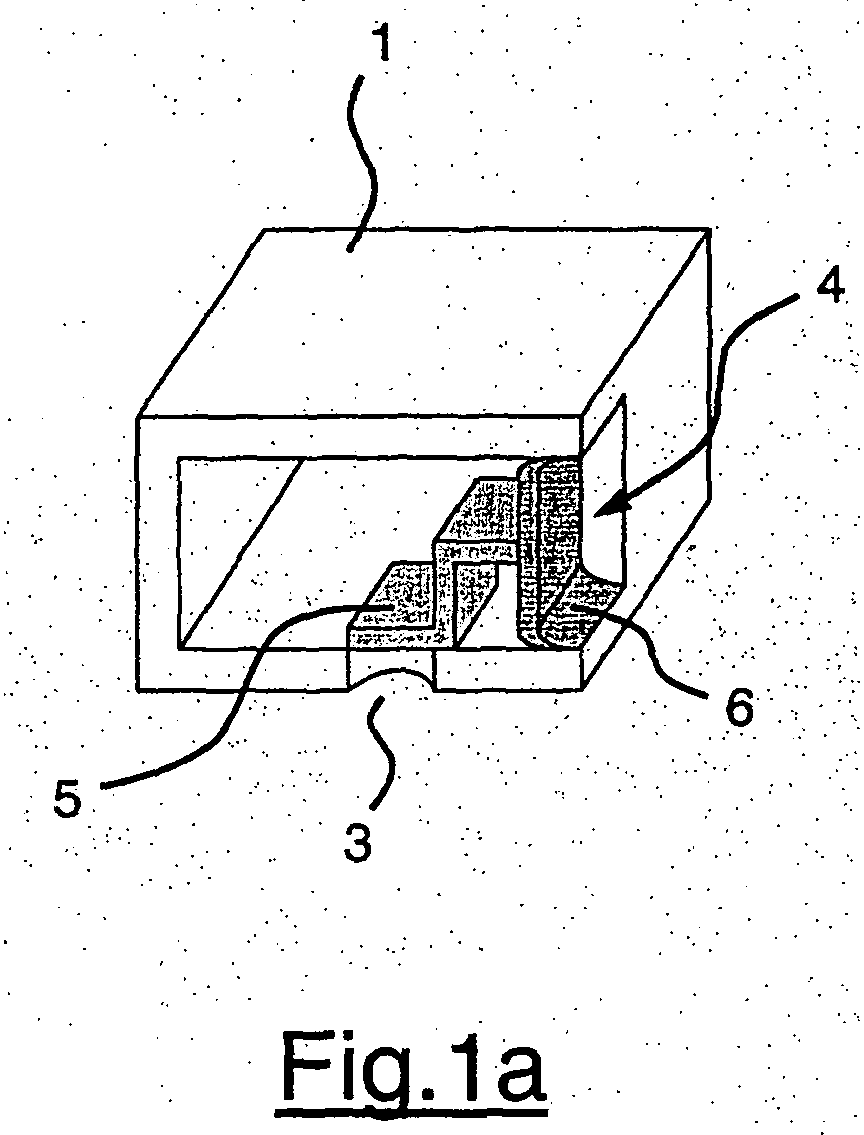
- a slider 5 acts with a Membrane 6 together, so that due to the pressure increase in the spray arm 1, the membrane 6 after 1 b, and thus in particular the slider 5 from the opening of the Pull the spray nozzle 3 away.
- the membrane pushes 6 the slider 5 back to the opening of the spray nozzle 3, as shown in the figure 1a is.
- Another embodiment of the opening or self-closing due to the changing pressure is shown in the figure 2a, 2b, wherein in the region of the nozzle opening.
- FIGS. 3a and 3b show another embodiment, which corresponds in the operation of the embodiment of Figure 1 a, 1 b, wherein in this Embodiment, the spring element comprises a return spring 9, with a displaceable mounted closure element 10 cooperates, which also has the opening cross-section the nozzle 3 either releases or closes, as in the synopsis of Figure 1 to recognize.
- the movement of the Closure element 10 not directly by the prevailing in the spray arm 1 water pressure, but on the dependent on the rotational speed of the spray arm 1 Centrifugal force. As the speed of the spray arm 1 but also directly from the pump pressure is dependent on an activation of the nozzle 3 by influencing the Pump pressure done.
- FIG. 6a and 6b Another variant of the invention is the figure 6a and 6b, wherein a return spring 29th with a freely slidably mounted end portion 11 of the spray arm 1 cooperates. It It goes without saying that if, due to the increasing centrifugal force, the Return spring 29 is stretched and the end portion 11 then against the force of Return spring 29 moves, so that the spray arm 1, shown in Figure 6a, extended is detected and in this way the spray arm 1 an extended area in the washing.
- FIGS. 7, 8, 9 and 10 show in particular further embodiments of the invention, it is the characteristic of these embodiments that not shown here Return springs with pivotally mounted additional spray arms 12 on the main spray arm 1 work together.
- the figure 7a and 7b on the portions of the main spray 1 in each case a Hilfssprüharm 12.1 and 12.2, because of the inner added weight 16 pivots due to increased rotational speed, shown in Figure 7b and 8a, and at low pump pressure and associated reduction in the Sprüharm beau is pivoted in an inactive position, as shown in Figure 7b is shown.
- FIG. 8a illustrates that both in the spray arm 1 and in the Hilfssprüharmen 12.1 and 12.2 each have an opening cross section 14 and 15 in the form a quarter circle is arranged.
- FIGS 9 and 10 show further embodiments according to the figure 7a, 7b, wherein here freely mounted Hilfssprüharme 12 are arranged, which individually or in angular position to each other are arranged pivotably on the main spray 1. These Hilfsssprüharme 12 act against the force of a spring, wherein the supply is also dependent on the pump pressure.
- the pump pressure such to adjust that the generated force is just able to the activatable nozzles 3 to to open.
- the volume flow decreases through the Nozzles 3 and 13 and thus the pressure of the liquid, whereby the nozzles 3 closed again become.
- the pressure is increased again, which in turn Opening the nozzles 3 leads.
Landscapes
- Washing And Drying Of Tableware (AREA)
- Detergent Compositions (AREA)
- Food-Manufacturing Devices (AREA)
Abstract
Die Erfindung betrifft eine Geschirrspülmaschine mit einem Spülbehälter, in dem wenigstens ein
Sprüharm (1) angeordnet ist, der in dem Spülbehälter um eine wenigstens annähernd vertikale
Achse (2) rotierend gelagert ist, wobei der Sprüharm (1) mit Sprühdüsen (3) bestückt ist, die
über eine Umwälzpumpe mit Spülflüssigkeit gespeist werden. Zur Steigerung der Effizienz des
Sprühdüsensystems sind im Bereich des Sprüharmes (1) elastische Mittel (4) vorgesehen, die
infolge des veränderbaren Pumpendrucks unterschiedliche Stellungen zur Aktivierung bzw.
Deaktivierung von an dem Sprüharm (1) angeordneten Sprühdüsen (3) einnehmen.

Description
Die Erfindung betrifft eine Geschirrspülmaschine mit einem Spülbehälter in dem wenigstens ein Sprüharm angeordnet ist, der in dem Spülbehälter um eine wenigstens annähernd vertikale Achse rotierend gelagert ist. Der Sprüharm ist mit Sprühdüsen bestückt, die über eine Umwälzpumpe mit Spülflüssigkeit gespeist werden. Aus dem Stand der Technik sind insbesondere Sprüharme bekannt, die derart ausgelegt sind, dass sie insbesondere Problemzonen im Spülbehälter berücksichtigen. So ist beispielsweise aus der EP 0 974 302 eine Spülvorrichtung für eine Geschirrspülmaschine bekannt, die einen Sprüharm aufweist, der über Eckspritzdüsen verfügt, die gesondert gespeist werden und nur in definierten Drehpositionen des Wasch- oder Spülarmes mit Spülflüssigkeit beaufschlagt werden. Auf diese Weise soll gewährleistet werden, dass insbesondere die in den Eckbereichen vorhandenen Problemzonen hinreichend mit Spülflüssigkeit beaufschlagt werden, um auf diese Weise eine effektive Reinigung von Geschirr, wie beispielsweise Töpfen, in den Eckbereichen zu erzielen. Hierzu weist der Sprüharm ein unterteiltes Kammersystem auf, wobei über die eine Kammer die Hauptsprühdüsen mit Spülflüssigkeit versorgt werden, und wobei die andere Kammer die Ecksprühdüsen mit Spülflüssigkeit versorgt. Die getrennte Versorgung erfolgt hierbei über getrennte Austrittsöffnungen im Nabenbereich des gelagerten Sprüharmes, wobei in definierten Drehpositionen des Sprüharmes die zweite Kammer in Strömungsverbindung zur Speisung der Ecksprühdüsen steht.The invention relates to a dishwasher with a washing container in which at least one Spray arm is arranged in the washing container by at least approximately vertical Axis is rotatably mounted. The spray arm is equipped with spray nozzles, which have a Circulation pump to be fed with rinsing liquid. From the prior art in particular spray arms, which are designed such that they in particular Consider problem areas in the washing container. For example, EP 0 974 302 a dishwasher for a dishwasher, which has a spray arm, the has corner nozzles, which are fed separately and only in defined Rotary positions of the washing or rinsing arm can be acted upon with rinsing liquid. To this Way, it should be ensured that in particular those in the corners Problem areas are sufficiently applied with rinsing liquid, in this way a Effective cleaning of dishes, such as pots, to achieve in the corner areas. For this purpose, the spray arm on a subdivided chamber system, wherein the one Main spray nozzles are supplied with rinsing liquid, and wherein the other chamber, the Ecksprühdüsen supplied with rinsing liquid. The separate supply takes place via separate outlet openings in the hub region of the mounted spray arm, wherein defined in Rotary positions of the spray arm, the second chamber in flow communication for feeding the Ecksprühdüsen stands.
Eine andere Lösung, um die Eckbereiche einer Spülkammer einer Geschirrspülmaschine mit Spülflüssigkeit zu versorgen, ist aus dem deutschen Gebrauchsmuster 29718 777 bekannt. Dort wird beschrieben, dass ein Hauptspülarm sowie ein Hilfsspülarm, der drehbar am Hauptspülarm befestigt ist, an der Wand der Geschirrspülmaschine entlang streicht und unter dem Einfluss der Zentrifugalkraft durch die Eckbereiche geführt wird. Allerdings ist bei dieser vorgeschlagenen Lösung der Gesamtwasserverbrauch sehr hoch, weil der Hilfsdüsenarm je nach Geometrie der Geschirrspülmaschine eng an der Innenwand entlang streicht und somit eine große Menge an Spülflüssigkeit in einen Bereich abgegeben wird, in dem diese nicht genutzt werden kann. Als nachteilig bei der erstgenannten Ausführungsform des Standes der Technik wird es angesehen, dass diese aufwendig aufgebaut ist, wobei bestimmte Bereiche des Geschirrs nicht ausreichend mit Sprühstrahlen beaufschlagt werden. Zu dem ist eine Veränderung der Sprühstrahlen derzeit nur sehr begrenzt über den Volumenstrom möglich. Another solution to the corner areas of a washing chamber of a dishwasher with To supply rinsing liquid is known from German Utility Model 29718 777. There is described that a Hauptpülarm and a Hilfsspülarm, rotatably on Main washing arm is attached, along the wall of the dishwasher along and under the influence of centrifugal force is passed through the corner areas. However, this one is proposed solution, the total water consumption very high, because the Hilfsdüsenarm ever according to the geometry of the dishwasher strikes closely along the inner wall and thus a large amount of rinsing liquid is discharged into a region in which they are not can be used. A disadvantage of the first-mentioned embodiment of the prior Technique it is considered that this is elaborately constructed, with certain areas of the dishes are not sufficiently charged with spray jets. To that is one Changing the spray jets currently only very limited on the volume flow possible.
Der Erfindung stellt sich somit das Problem, die Effizienz von an einem Sprüharm vorgesehenen Sprühdüsen zu verbessern, wobei insbesondere die Sprühstrahlen eine höhere Abdeckung des Spülraumes geben sollen.The invention thus poses the problem of the efficiency of a spray arm to improve spray nozzles, in particular the spray jets higher Cover the washroom should give.
Erfindungsgemäß wird dieses Problem mit den Merkmalen des Anspruchs 1 gelöst. Vorteilhafte
Ausgestaltungen und Weiterbildungen der Erfindung ergeben sich aus den nachfolgenden
Unteransprüchen.According to the invention this problem is solved with the features of
Die mit der Erfindung erreichbaren Vorteile bestehen dadurch, dass die Ausnutzung des Druckes im Sprüharm (z.B. beeinflussbar durch die Veränderung der Umwälzpumpendrehzahl) und der damit einhergehenden Geometrieänderung keine zusätzlichen Aktoren benötigt, was insbesondere dadurch erreicht wird, dass im Bereich des Sprüharmes elastische Mittel vorgesehen sind, die infolge des veränderbaren Pumpendrucks unterschiedliche Stellungen zur Aktivierung bzw. Deaktivierung von an dem Sprüharm angeordneten Sprühdüsen einnehmen. Durch diese Ausbildung wird auch erreicht, dass infolge des veränderten Pumpendruckes ein sogenanntes pulsierendes Besprühen des Geschirrs erfolgt, was zu einer effektiveren Reinigung führt. Dabei können die elastischen Mittel zur Ansteuerung von zusätzlich am Sprüharm vorgesehenen Sprühdüsen und/oder Sprüharmbereichen vorgesehen sein. Die elastischen Mittel sind dabei als Federelemente ausgebildet, die entweder eine unmittelbare Schließung oder Öffnung der Düsenöffnung bewirken, oder dass sie in Wirkverbindung mit verschwenkbaren oder verschiebbaren Armbereichen stehen, zur Aktivierung bzw. Deaktivierung dieser Armbereiche, respektive der Sprühdüsen.The achievable with the invention advantages are that the use of the Pressure in the spray arm (for example, influenced by the change in the circulation pump speed) and the concomitant geometry change requires no additional actuators, which is achieved in particular by elastic means in the area of the spray arm are provided, due to the variable pump pressure different positions for Activation or deactivation of arranged on the spray arm spray nozzles. Through this training is also achieved that as a result of the changed pump pressure a so-called pulsating spraying of the dishes takes place, resulting in a more effective Cleaning leads. In this case, the elastic means for controlling in addition to Spray arm provided spray nozzles and / or Sprüharmbereichen be provided. The elastic means are designed as spring elements, either an immediate Closure or opening of the nozzle opening effect, or that they are in operative connection with pivotable or displaceable arm areas are, for activation or Deactivation of these arm areas, respectively the spray nozzles.
Hierzu kann das Federelement als ein elastisches Formteil ausgebildet sein, welches infolge der Druckerhöhung den Öffnungsquerschnitt der Düse freigibt, wobei anders herum infolge der Druckabsenkung eine selbsttätige Schließung durch das elastische Formteil wieder hervorgerufen wird. Auch kann dabei das elastische Formteil aus einem lippenartigen Ringelement bestehen, welches in Folge seiner elastischen Rückverformung bei Druckabfall zur Schließung der Düsenöffnung führt. Durch Ausnutzung des variierenden Druckes können nun beim Sprüharm zusätzliche Sprühdüsen aktiviert werden, hierbei werden z.B. unterschiedliche Pumpendrehzahlen verwendet, um den Sprüharm selbst mit unterschiedlichen Drücken zu betreiben. Bei einer Standardpumpendrehzahl werden nicht alle Sprühdüsen mit Wasser versorgt. Bei einer erhöhten Drehzahl soll durch Ausnutzung des Druckes z.B. eine zusätzliche Sprühdüse hinzugeschaltet werden. Hierzu kann beispielsweise das elastische Formteil als Membran ausgelegt sein, das sich erst bei einem bestimmten Druck verformt. Ein an der Membran angebrachter Schieber sorgt dafür, dass bei verformter Membran eine zusätzliche Düse, welche vorher verschlossen war, wieder freigegeben wird. Weitere Vorteile dieser Lösung sind es, dass unabhängig von der Membran sich die Düsen ab einem bestimmten Druck zu- oder abschalten und eine Intensivspülzone erzeugt wird, ohne dass zusätzliche Aktoren zur Sprühstrahländerung erforderlich sind. Hierbei können die Sprühstrahlenvielzahl dem gewählten Programm entsprechend vorgegeben werden bzw. verändert werden.For this purpose, the spring element may be formed as an elastic molded part, which as a result the pressure increase the opening cross-section of the nozzle releases, the other way round due to the Pressure reduction an automatic closure by the elastic molded part again is caused. Also, while the elastic molding of a lip-like Ring element consist, which as a result of its elastic recovery in pressure drop to Closing the nozzle opening leads. By taking advantage of the varying pressure can now the spray arm additional spray nozzles are activated, this example. different Pump speeds are used to move the spray arm itself with different pressures operate. At a standard pump speed, not all spray nozzles will be watered provided. At an increased speed, by utilizing the pressure, e.g. an additional Spray nozzle are switched on. For this example, the elastic molding as Membrane designed to deform only at a certain pressure. An at the Diaphragm-mounted slider ensures that when deformed membrane an additional Nozzle, which was previously closed, is released again. Further advantages of this solution it is that, irrespective of the diaphragm, the or switch off and an intensive flushing zone is generated without additional actuators for Spray jet change are required. Here, the spray jet variety the selected program can be specified or changed accordingly.
Nach einer besonders vorteilhaften Weiterbildung der Erfindung umfasst das Federelement eine
Rückstellfeder, die mit einem verschiebbar gelagerten Verschlusselement zusammenwirkt,
welches den Öffnungsquerschnitt der Düse abdeckt. Die Rückstellfeder wird der gleichen
Aufgabe gerecht, wie beispielsweise der Membran. Bei einer anderen Ausführungsform wirkt
beispielsweise eine Rückstellfeder mit einem am Sprüharm angeordneten, verschiebbar
gelagerten Schlitten zusammen, der mehrere Düsen abdeckt bzw. bei Druckerhöhung wieder
freigibt. Gemäß einer weiteren Ausführungsform wirkt eine Rückstellfeder mit einem freien,
verschiebbar gelagerten Endbereich des Sprüharmes zusammen, so dass eine
Längenänderung des Sprüharmes hervorgerufen wird, was insbesondere durch
Fliehkrafteinwirkung, ebenfalls bedingt durch Druckerhöhung, hervorgerufen werden kann.
Auch ist es denkbar, dass die Rückstellfeder mit schwenkbar gelagerten zusätzlichen
Sprüharmen am Hauptsprüharm zusammenwirkt, wobei die Rückstellfeder den zusätzlichen
Sprüharm bei einer bestimmen Drehzahl wieder in seine Ausgangslage zurück verschwenkt.
Wird die Drehzahl durch Druckerhöhung des Sprüharmes erhöht, schwenken die
entsprechenden zusätzlichen Sprüharme aus und überstreichen somit zusätzliche Bereiche im
Sprühraum.According to a particularly advantageous embodiment of the invention, the spring element comprises a return spring, which cooperates with a displaceably mounted closure element which covers the opening cross-section of the nozzle. The return spring does the same job, such as the membrane. In another embodiment, for example, a return spring cooperates with a sliding arm mounted on the spray arm, which covers a plurality of nozzles or releases them again when the pressure increases. According to a further embodiment, a return spring cooperates with a free, displaceably mounted end region of the spray arm, so that a change in length of the spray arm is caused, which in particular by centrifugal force, also caused by pressure increase, can be caused.
It is also conceivable that the return spring interacts with pivotally mounted additional spray arms on the main spray arm, wherein the return spring pivots the additional spray arm at a certain speed back to its original position. If the speed is increased by increasing the pressure of the spray arm, the corresponding additional spray arms swing out and thus cover additional areas in the spray room.
Ein Ausführungsbeispiel der Erfindung ist in den Zeichnungen rein schematisch dargestellt und wird nachfolgend näher beschrieben; es zeigen:
- Figur 1a, 1 b
- ein elastisches Formteil in Zusammenwirkung mit einer Düsenöffnung;
- Figur 2a, 2b
- eine andere Ausführungsform gemäß der
Figur 1; - Figur 3a, 3b
- zeigt ein verschiebbares Verschlusselement mit Rückstellfeder;
- Figur 4a, 4b
- zeigt einen verschiebbaren Schlitten an einem Sprüharm;
- Figur 5a, 5b
- zeigt eine weitere Ansicht in Seitenansicht der Ausführungsform gemäß der Figur 4a, 4b;
- Figur 6a, 6b
- zeigt einen verschiebbaren Endbereich eines Sprüharmes unter Einwirkung einer Rückstellfeder;
- Figur 7a, 7b
- zeigt einen Sprüharm mit zusätzlichen Hilfssprüharmen, die ebenfalls in Wirkverbindung mit einer Rückstellfeder verschwenkbar am Hauptsprüharm gelagert sind;
- Figur 8a, 8b
- zeigt eine geschnittene Darstellung gemäß der Figur 7a, 7b, wobei einmal die eingeschwenkte und einmal die aufgeschwenkte Situation des Hilfssprüharmes in der geschnittenen Ansicht dargestellt ist;
Figuren - zeigen eine weitere Ausführungsform eines Hauptsprüharmes mit Hilfssprüharmen, die ebenfalls mit Rückstellfedern zusammenwirken.
- FIG. 1a, 1b
- an elastic molding in cooperation with a nozzle opening;
- Figure 2a, 2b
- another embodiment according to the figure 1;
- Figure 3a, 3b
- shows a sliding closure element with return spring;
- Figure 4a, 4b
- shows a sliding carriage on a spray arm;
- Figure 5a, 5b
- shows a further view in side view of the embodiment according to the figure 4a, 4b;
- Figure 6a, 6b
- shows a displaceable end portion of a spray arm under the action of a return spring;
- Figure 7a, 7b
- shows a spray arm with additional Hilfsssprüharmen, which are also mounted in operative connection with a return spring pivotally mounted on the main spray;
- Figure 8a, 8b
- shows a sectional view according to the figure 7a, 7b, showing once the pivoted and once the pivoted situation of Hilfssprüharmes in the sectional view;
- FIGS. 9, 10
- show a further embodiment of a Hauptsprüharmes with Hilfsssprüharmen, which also cooperate with return springs.
Der Erfindungsgegenstand betrifft eine Geschirrspülmaschine, die nicht näher im Einzelnen
gezeigt wird, in dem ein Spülbehälter vorgesehen ist, in dem mindestens ein Sprüharm 1
angeordnet ist, der in dem Sprühraum um eine vertikale Achse 2 rotierend gelagert ist, wobei
der Sprüharm 1 mit Sprühdüsen 3 bzw. 13 bestückt ist, die über eine ebenfalls nicht näher
dargestellte Umwälzpumpe mit Spülflüssigkeit gespeist werden. Den Darstellungen der Figuren
1 bis 8 ist es nun zu Eigen, dass sie jeweils die geschlossene bzw. die offene Stellung einer
Düse 3 zeigen oder die Aktivierung bzw. Deaktivierung von Sonderbauteilen am Sprüharm 1.
Bei den Figuren 9 und 10 ist die Aktivierung bzw. Deaktivierung von Sonderbauteilen am
Sprüharm 1 innerhalb einer Zeichnung gezeigt. Die Düsen 13 sind permanent geöffnet.The subject invention relates to a dishwasher, which does not detail in detail
in which a washing container is provided, in which at least one spray arm. 1
is arranged, which is rotatably mounted in the spray chamber about a
Im Bereich des Sprüharmes 1 sind elastische Mittel 4 vorgesehen, die infolge des
veränderbaren Pumpendrucks eine erste geschlossene, und eine zweite geöffnete Stellung,
einnehmen, um auf diese Weise, die an dem Sprüharm 1 vorgesehenen Sprühdüsen 3
entweder zu aktivieren oder zu deaktivieren. Die elastischen Mittel 4 können somit zur
Ansteuerung von zusätzlichen am Sprüharm 1 vorgesehenen Düsen 3 und/oder
Sprüharmbereichen vorgesehen sein. Dabei sind die elastischen Mittel 4 als Federelemente
ausgebildet, die entweder eine unmittelbare Schließung oder Öffnung der Düsenöffnung
bewirken (s. Figuren 1, 2, 3, 4 und 5) oder die in Wirkverbindung mit schwenkbaren oder
verschiebbaren Armbereichen (s. Figuren 6, 7, 8, 9 und 10) stehen, zur Aktivierung bzw. zur
Deaktivierung dieser Armbereiche, respektive der Sprühdüsen 3.In the area of the
So zeigt beispielsweise die Figur 1 und 2 ein Federelement, das als ein elastisches Formteil
ausgebildet ist. Wie aus der Figur 1 zu erkennen ist, wirkt dabei ein Schieber 5 mit einer
Membran 6 zusammen, so dass infolge der Druckerhöhung im Sprüharm 1 die Membran 6 nach
außen gedrückt wird, Figur 1 b, und somit insbesondere den Schieber 5 von der Öffnung der
Sprühdüse 3 wegzieht. Erniedrigt sich der Druck im Sprüharm 1 wieder, so drückt die Membran
6 den Schieber 5 wieder auf die Öffnung der Sprühdüse 3, wie dies in der Figur 1a dargestellt
ist. Eine andere Ausführungsform der Öffnung bzw. Selbstschließung infolge des sich
verändernden Druckes ist in der Figur 2a, 2b dargestellt, wobei im Bereich der Düsenöffnung 3
ein als elastisches Formteil bestehendes lippenartiges Ringelement 7 vorgesehen ist, welches
bei erhöhtem Druck sich öffnet, Figur 2b, und bei ablassendem Druck sich selbsttätig schließt,
wie dies in der Figur 2a dargestellt ist. Die Figur 3a und 3b zeigt eine andere Ausführungsform,
die in der Wirkungsweise der Ausführungsform der Figur 1 a, 1 b entspricht, wobei bei dieser
Ausführungsform das Federelement eine Rückstellfeder 9 umfasst, die mit einem verschiebbar
gelagerten Verschlusselement 10 zusammenwirkt, welches ebenfalls den Öffnungsquerschnitt
der Düse 3 entweder freigibt oder verschließt, wie dies in der Zusammenschau der Figur 1 zu
erkennen ist. Bei dieser und den nachfolgend dargestellten Varianten erfolgt die Bewegung des
Verschlusselements 10 nicht direkt durch den im Sprüharm 1 vorherrschenden Wasserdruck,
sondern über die von der Umdrehungsgeschwindigkeit des Sprüharms 1 abhängigen
Zentrifugalkraft. Da die Geschwindigkeit des Sprüharms 1 aber auch direkt vom Pumpendruck
abhängig ist, kann auch hier eine Aktivierung der Düse 3 durch Beeinflussung des
Pumpendrucks erfolgen.For example, Figure 1 and 2 shows a spring element, as an elastic molding
is trained. As can be seen from the figure 1, a
Gemäß der Figur 4a und 4b in Zusammenschau mit der Figur 5a und 5b wird ein
verschiebbarer Schlitten 8 dargestellt, der gegen die Wirkung einer Rückstellfeder (19, s. Fig. 5)
verschiebbar am Sprüharm 1 gelagert ist. Es versteht sich nun von selbst, dass, wenn infolge
der Druckerhöhung die Fliehkräfte steigen, der Schlitten 8 gegen die Federkraft der
Rückstellfeder 9 sich am Arm 1 verschiebt, so dass auf diese Weise zusätzliche Düsen 3
freigegeben werden, um somit eine effektivere Reinigung zu erzielen. Dabei sind in dem
Schlitten in Längsrichtung des Sprüharms hintereinander verschiedene Blenden 3.1, 3.2, 3.3
und 3.4 angeordnet, mit denen unterschiedliche Sprühstrahlcharakteristiken erreicht werden
können. Die jeweilige Blende kann über den Pumpendruck und die davon abhängige Fliehkraft
eingestellt werden.According to the figure 4a and 4b in conjunction with the figure 5a and 5b is a
Eine andere Variante der Erfindung stellt die Figur 6a und 6b dar, wobei eine Rückstellfeder 29
mit einem freien verschiebbar gelagerten Endbereich 11 des Sprüharmes 1 zusammenwirkt. Es
versteht sich von selbst, dass, wenn infolge der sich erhöhenden Zentrifugalkraft, die
Rückstellfeder 29 gedehnt wird und sich der Endbereich 11 dann gegen die Kraft der
Rückstellfeder 29 verschiebt, so dass der Sprüharm 1, dargestellt in der Figur 6a, verlängert
wird und auf diese Weise der Sprüharm 1 einen erweiterten Bereich im Spülbehälter erfasst.Another variant of the invention is the figure 6a and 6b, wherein a return spring 29th
with a freely slidably mounted
Die Figuren 7, 8, 9 und 10 zeigen insbesondere weitere Ausführungsformen der Erfindung,
wobei es das Charakteristikum dieser Ausführungsformen ist, dass hier nicht gezeigte
Rückstellfedern mit schwenkbar gelagerten zusätzlichen Sprüharmen 12 am Hauptsprüharm 1
zusammen wirken. So zeigt die Figur 7a und 7b auf den Teilbereichen des Hauptsprüharmes 1
jeweils einen Hilfssprüharm 12.1 und 12.2, der wegen des innen angeordneten Zusatzgewichts
16 infolge erhöhter Drehgeschwindigkeit aufschwenkt, dargestellt in Figur 7b und 8a, und bei
niedrigem Pumpendruck und einer damit verbundenen Verringerung der
Sprüharmgeschwindigkeit in eine Inaktivlage verschwenkt wird, wie dies in der Figur 7b
dargestellt ist. Es versteht sich nun von selbst, dass, wenn die zusätzlichen Hilfssprüharme 12.1
und 12.2 ausgeschwenkt sind, auch die an dem Sprüharm 12.1 und 12.2 vorgesehenen Düsen
mit Spülflüssigkeit versorgt werden, so dass sich eine effektive Reinigung ergibt. Die
geschnittene Darstellung der Figur 8a und 8b verdeutlicht, dass sowohl im Sprüharm 1 als auch
in den Hilfssprüharmen 12.1 bzw. 12.2 jeweils ein Öffnungsquerschnitt 14 bzw. 15 in Form
eines Viertelkreises angeordnet ist. Beim Verschwenken der Hilfssprüharme 12.1 bzw. 12.2
liegen diese Öffnungsquerschnitte 14 und 15 übereinander, so dass die Spülflüssigkeit vom
Hauptsprüharm 1 in die Hilfssprüharme 12.1 und 12.2 fließen kann. Die Verschlussstellung ist in
der Figur 8a dargestellt.FIGS. 7, 8, 9 and 10 show in particular further embodiments of the invention,
it is the characteristic of these embodiments that not shown here
Return springs with pivotally mounted
Die Figuren 9 und 10 zeigen weitere Ausführungsformen gemäß der Figur 7a, 7b, wobei hier
frei gelagerte Hilfssprüharme 12 angeordnet sind, die einzeln oder in Winkelstellung zueinander
verschwenkbar am Hauptsprüharm 1 angeordnet sind. Auch diese Hilfssprüharme 12 wirken
gegen die Kraft einer Feder, wobei die Versorgung ebenfalls vom Pumpendruck abhängig ist.Figures 9 and 10 show further embodiments according to the figure 7a, 7b, wherein here
freely mounted
Durch geschickte Ansteuerung der Umwälzpumpe ist es möglich, den Pumpendruck derart
einzustellen, dass die erzeugte Kraft gerade in der Lage ist, die aktivierbaren Düsen 3 zu
öffnen. Infolge des zusätzlichen Öffnungsquerschnitts sinkt dann der Volumenstrom durch die
Düsen 3 und 13 und damit der Druck der Flüssigkeit, wodurch die Düsen 3 wieder geschlossen
werden. Mit dem Schließen der Düsen 3 wird der Druck wieder erhöht, was wiederum zum
Öffnen der Düsen 3 führt. Durch das abwechselnde Öffnen und Schließen der Düsen 3 wird ein
oszillierender Sprühstrahl erzeugt, dessen Reinigungswirkung besser als der eines
permanenten Strahls ist.By skillful control of the circulation pump, it is possible the pump pressure such
to adjust that the generated force is just able to the
Claims (10)
dadurch gekennzeichnet, dass im Bereich des Sprüharmes (1) elastische Mittel (4) vorgesehen sind, die infolge des veränderbaren Pumpendrucks unterschiedliche Stellungen zur Aktivierung bzw. Deaktivierung von an dem Sprüharm (1) angeordneten Sprühdüsen (3) einnehmen.Dishwasher with a rinsing container, in which at least one spray arm is arranged, which is rotatably mounted in the washing container about an at least approximately vertical axis, wherein the spray arm is equipped with spray nozzles, which are fed via a circulating pump with rinsing liquid,
characterized in that in the region of the spray arm (1) elastic means (4) are provided which occupy different positions due to the variable pump pressure for activation or deactivation of the spray arm (1) arranged spray nozzles (3).
dadurch gekennzeichnet, dass die elastischen Mittel (4) zur Ansteuerung von zusätzlich am Sprüharm (1) vorgesehenen Sprühdüsen (3) und/oder Sprüharmbereichen (8, 10, 12) vorgesehen sind.Dishwasher according to claim 1,
characterized in that the elastic means (4) for controlling additionally on the spray arm (1) provided spray nozzles (3) and / or Sprüharmbereichen (8, 10, 12) are provided.
dadurch gekennzeichnet, dass die elastischen Mittel (4) als Federelemente (9; 19; 29) ausgebildet sind, die entweder eine unmittelbare Schließung oder Öffnung der Düsenöffnung bewirken, oder dass sie in Wirkverbindung mit verschwenkbaren oder verschiebbaren Armbereichen (12) stehen, zur Aktivierung bzw. Deaktivierung dieser Armbereiche (12), respektive der in ihnen angeordneten Sprühdüsen (3).Dishwasher according to claim 2,
characterized in that the elastic means (4) are designed as spring elements (9; 19; 29) which either cause an immediate closure or opening of the nozzle opening, or that they are in operative connection with pivotable or displaceable arm regions (12) for activation or deactivation of these arm regions (12), respectively, the spray nozzles (3) arranged in them.
dadurch gekennzeichnet, dass das Federelement als ein elastisches Formteil vorzugsweise Membran (6) ausgebildet ist, welches infolge der Druckerhöhung den Öffnungsquerschnitt der Düse (3) freigibt.Dishwasher according to claim 3,
characterized in that the spring element is formed as an elastic molded part preferably membrane (6) which releases the opening cross-section of the nozzle (3) due to the pressure increase.
dadurch gekennzeichnet, dass das elastische Formteil aus einem lippenartigen Ringelement (7) besteht.Dishwasher according to claims 3 and 4,
characterized in that the elastic molded part consists of a lip-like ring element (7).
dadurch gekennzeichnet, dass das Federelement eine Rückstellfeder (9) umfasst, die mit einem verschiebbar gelagerten Verschlusselement (10) zusammenwirkt, welches den Öffnungsquerschnitt der Düse (3) abdeckt. Dishwasher according to claim 3 to 5,
characterized in that the spring element comprises a return spring (9) which cooperates with a displaceably mounted closure element (10) which covers the opening cross-section of the nozzle (3).
dadurch gekennzeichnet, dass eine Rückstellfeder (19) mit einem am Sprüharm (1) angeordneten verschiebbar gelagerten Schlitten (8) zusammenwirkt, der mehrere Düsen (3) abdeckt.Dishwasher according to claim 3 to 6,
characterized in that a return spring (19) with a spray arm (1) arranged slidably mounted carriage (8) cooperates, which covers a plurality of nozzles (3).
dadurch gekennzeichnet, dass eine Rückstellfeder (29) mit einem freien, verschiebbar gelagerten Endbereich (11) des Sprüharms (1) zusammenwirkt.Dishwasher according to claim 3 to 7,
characterized in that a return spring (29) cooperates with a free, displaceably mounted end region (11) of the spray arm (1).
dadurch gekennzeichnet, dass Rückstellfedern mit schwenkbar gelagerten zusätzlichen Sprüharmen (12) am Hauptsprüharm (1) zusammenwirken.Dishwasher according to claim 3,
characterized in that return springs interact with pivotally mounted additional spray arms (12) on the main spray arm (1).
dadurch gekennzeichnet, dass der Druck der Umwälzpumpe derart an den Öffnungsquerschnitt aller in den Sprüharmen angeordneten Sprühdüsen eingepasst ist, dass ein oszillierendes Öffnen und Schließen der aktivierbaren Sprühdüsen (3) erfolgt.Method for operating a dishwasher according to at least one of claims 1 to 9,
characterized in that the pressure of the circulation pump is so fitted to the opening cross section of all arranged in the spray arms spray nozzles, that an oscillating opening and closing of the activatable spray nozzles (3).
Priority Applications (1)
| Application Number | Priority Date | Filing Date | Title |
|---|---|---|---|
| PL05006974T PL1586264T3 (en) | 2004-04-15 | 2005-03-31 | Dishwasher with a tub and a least one sprayarm arranged within the tub |
Applications Claiming Priority (2)
| Application Number | Priority Date | Filing Date | Title |
|---|---|---|---|
| DE102004018878 | 2004-04-15 | ||
| DE102004018878A DE102004018878B4 (en) | 2004-04-15 | 2004-04-15 | Dishwasher with a washing container in which at least one spray arm is arranged |
Publications (3)
| Publication Number | Publication Date |
|---|---|
| EP1586264A2 true EP1586264A2 (en) | 2005-10-19 |
| EP1586264A3 EP1586264A3 (en) | 2008-07-23 |
| EP1586264B1 EP1586264B1 (en) | 2009-03-18 |
Family
ID=34934604
Family Applications (1)
| Application Number | Title | Priority Date | Filing Date |
|---|---|---|---|
| EP05006974A Expired - Lifetime EP1586264B1 (en) | 2004-04-15 | 2005-03-31 | Dishwasher with a tub and a least one sprayarm arranged within the tub |
Country Status (4)
| Country | Link |
|---|---|
| EP (1) | EP1586264B1 (en) |
| AT (1) | ATE425695T1 (en) |
| DE (2) | DE102004018878B4 (en) |
| PL (1) | PL1586264T3 (en) |
Cited By (9)
| Publication number | Priority date | Publication date | Assignee | Title |
|---|---|---|---|---|
| WO2011154471A1 (en) * | 2010-06-10 | 2011-12-15 | Aktiebolaget Electrolux | A dishwasher |
| EP2454983A1 (en) * | 2010-11-15 | 2012-05-23 | Electrolux Home Products Corporation N.V. | Dishwasher with thermally adjusting spray nozzles |
| WO2015018671A1 (en) * | 2013-08-06 | 2015-02-12 | Arcelik Anonim Sirketi | A dishwasher with improved washing effectiveness |
| EP2891446A1 (en) * | 2014-01-02 | 2015-07-08 | Miele & Cie. KG | Dishwasher |
| WO2015149859A1 (en) * | 2014-04-03 | 2015-10-08 | Electrolux Appliances Aktiebolag | Wash arm arrangement |
| WO2018103952A1 (en) * | 2016-12-07 | 2018-06-14 | Arcelik Anonim Sirketi | A dishwasher |
| US10058229B2 (en) * | 2011-09-22 | 2018-08-28 | Whirlpool Corporation | Dishwasher with sprayer |
| US10213085B2 (en) | 2013-07-01 | 2019-02-26 | Whirlpool Corporation | Dishwasher for treating dishes |
| CN111616657A (en) * | 2020-06-17 | 2020-09-04 | 珠海格力电器股份有限公司 | Spray Arm, Dishwasher and Dishwasher Control Method |
Families Citing this family (7)
| Publication number | Priority date | Publication date | Assignee | Title |
|---|---|---|---|---|
| DE102005013127B4 (en) * | 2004-11-12 | 2007-08-23 | Aweco Appliance Systems Gmbh & Co. Kg | Spraying device for spraying a working fluid |
| DE102010032005A1 (en) | 2010-07-22 | 2012-01-26 | Michael Heidan | Quadratic dishwasher, has large spray arm moved around rotational axis, and small spray arm whose movements stand independence of movements of large spray arm, where small spray arm covers entire area of base surface of dishwasher |
| DE102010032006A1 (en) | 2010-07-22 | 2012-01-26 | Michael Heidan | Dishwasher has perpendicular rotating axis rotating around rotating spraying arm and for discharging water jets with pressure water |
| DE102012103445B4 (en) | 2012-04-19 | 2018-10-31 | Miele & Cie. Kg | Dishwasher, in particular commercial dishwasher |
| US9962063B2 (en) | 2014-03-13 | 2018-05-08 | Whirlpool Corporation | Dishwasher rack spray assembly |
| DE102018201218A1 (en) * | 2018-01-26 | 2019-08-01 | Meiko Maschinenbau Gmbh & Co. Kg | WASHING SYSTEM FOR CLEANING CLEANING GOODS |
| DE102019212952B4 (en) * | 2019-08-28 | 2023-05-11 | Blanco Gmbh + Co Kg | Cleaning device and method for operating a cleaning device |
Family Cites Families (8)
| Publication number | Priority date | Publication date | Assignee | Title |
|---|---|---|---|---|
| US1997450A (en) * | 1933-03-17 | 1935-04-09 | Richard Merrifield | Spray projector for automatic dish washing and drying machine |
| US5944037A (en) * | 1996-10-16 | 1999-08-31 | Samsung Electronics Co., Ltd. | Water spray apparatus for tableware washing machine |
| IT1289398B1 (en) * | 1996-11-06 | 1998-10-02 | Electrolux Zanussi Elettrodome | DISHWASHER WITH PERFECTED SPRAYING VEHICLES |
| JP3651240B2 (en) * | 1998-03-18 | 2005-05-25 | 松下電器産業株式会社 | Dishwasher |
| DE19832982C2 (en) * | 1998-07-22 | 2000-08-03 | Premark Feg Llc | Dishwashing device for a dishwasher |
| IT1311215B1 (en) * | 1999-03-29 | 2002-03-04 | Electrolux Zanussi Elettrodome | DISHWASHER WITH PERFECTED SPRAYING VEHICLES |
| IT1311214B1 (en) * | 1999-03-29 | 2002-03-04 | Electrolux Zanussi Elettrodome | DISHWASHER WITH BUTTON WATER JETS |
| DE10134917B4 (en) * | 2001-07-18 | 2006-03-16 | AEG Hausgeräte GmbH | Dishwasher with variable liquid distribution |
-
2004
- 2004-04-15 DE DE102004018878A patent/DE102004018878B4/en not_active Expired - Fee Related
-
2005
- 2005-03-31 AT AT05006974T patent/ATE425695T1/en not_active IP Right Cessation
- 2005-03-31 DE DE502005006856T patent/DE502005006856D1/en not_active Expired - Lifetime
- 2005-03-31 EP EP05006974A patent/EP1586264B1/en not_active Expired - Lifetime
- 2005-03-31 PL PL05006974T patent/PL1586264T3/en unknown
Cited By (19)
| Publication number | Priority date | Publication date | Assignee | Title |
|---|---|---|---|---|
| WO2011154471A1 (en) * | 2010-06-10 | 2011-12-15 | Aktiebolaget Electrolux | A dishwasher |
| CN103249345B (en) * | 2010-11-15 | 2018-06-19 | 伊莱克斯家用产品公司 | Dishwasher with adjustable nozzle |
| CN103249345A (en) * | 2010-11-15 | 2013-08-14 | 伊莱克斯家用产品公司 | Dishwasher |
| AU2011331382B2 (en) * | 2010-11-15 | 2016-09-08 | Electrolux Home Products Corporation N.V. | Dishwasher with adjustable nozzle |
| RU2571188C2 (en) * | 2010-11-15 | 2015-12-20 | Электролюкс Хоум Продактс Корпорейшн Н.В. | Dishwasher |
| US9420938B2 (en) | 2010-11-15 | 2016-08-23 | Electrolux Home Products Corporation N.V. | Dishwasher with spray device having an adjustable nozzle |
| WO2012065873A3 (en) * | 2010-11-15 | 2012-07-12 | Electrolux Home Products Corporation N.V. | Dishwasher with adjustable nozzle |
| EP2454983A1 (en) * | 2010-11-15 | 2012-05-23 | Electrolux Home Products Corporation N.V. | Dishwasher with thermally adjusting spray nozzles |
| US10602907B2 (en) | 2011-09-22 | 2020-03-31 | Whirlpool Corporation | Dishwasher with sprayer |
| US10058229B2 (en) * | 2011-09-22 | 2018-08-28 | Whirlpool Corporation | Dishwasher with sprayer |
| US10213085B2 (en) | 2013-07-01 | 2019-02-26 | Whirlpool Corporation | Dishwasher for treating dishes |
| AU2014304747B2 (en) * | 2013-08-06 | 2016-11-03 | Arcelik Anonim Sirketi | A dishwasher with improved washing effectiveness |
| US10610079B2 (en) | 2013-08-06 | 2020-04-07 | Arcelik Anonim Sirketi | Dishwasher having multiple spray arms for improved washing effectiveness |
| WO2015018671A1 (en) * | 2013-08-06 | 2015-02-12 | Arcelik Anonim Sirketi | A dishwasher with improved washing effectiveness |
| EP2891446A1 (en) * | 2014-01-02 | 2015-07-08 | Miele & Cie. KG | Dishwasher |
| WO2015149859A1 (en) * | 2014-04-03 | 2015-10-08 | Electrolux Appliances Aktiebolag | Wash arm arrangement |
| WO2018103952A1 (en) * | 2016-12-07 | 2018-06-14 | Arcelik Anonim Sirketi | A dishwasher |
| CN111616657A (en) * | 2020-06-17 | 2020-09-04 | 珠海格力电器股份有限公司 | Spray Arm, Dishwasher and Dishwasher Control Method |
| CN111616657B (en) * | 2020-06-17 | 2025-07-29 | 珠海格力电器股份有限公司 | Spray arm, dish washing machine and dish washing machine control method |
Also Published As
| Publication number | Publication date |
|---|---|
| DE102004018878A1 (en) | 2005-11-10 |
| ATE425695T1 (en) | 2009-04-15 |
| DE502005006856D1 (en) | 2009-04-30 |
| PL1586264T3 (en) | 2009-06-30 |
| EP1586264A3 (en) | 2008-07-23 |
| DE102004018878B4 (en) | 2006-01-05 |
| EP1586264B1 (en) | 2009-03-18 |
Similar Documents
| Publication | Publication Date | Title |
|---|---|---|
| EP1586264A2 (en) | Dishwasher with a tub and a least one sprayarm arranged within the tub | |
| EP2192852B1 (en) | Dishwasher | |
| EP2891446B1 (en) | Dishwasher | |
| DE60013345T2 (en) | Dishwasher with pulsating water jets | |
| DE2621307C2 (en) | Method for cleaning a liquid filter against which excess pressure flows, and device for carrying out the method | |
| EP0223879B1 (en) | Manual device for cleaning blocked drains | |
| DE60028277T2 (en) | Dishwasher with spray arms | |
| EP2601877B1 (en) | Dishwasher with automatic reversal of the direction of rotation of the spray arm | |
| EP0018527A2 (en) | Return-flow filtration device, especially for a domestic water system | |
| DE102007057336A1 (en) | Water-conducting household appliance with a water diverter | |
| DE102007056922A1 (en) | Water-carrying household appliance with a water diverter | |
| EP3085293A1 (en) | Spray arm assembly and dishwasher | |
| EP2601878B1 (en) | Dishwasher with automatic reversal of the direction of rotation of the spray arm | |
| DE4132350C2 (en) | Sanitary device | |
| DE102020115594A1 (en) | Compound water outlet device with a water inlet and water stop control and a water outlet switch and toilet | |
| DE1675528C3 (en) | Changeover switch for a faucet on bathtubs | |
| DE69721161T2 (en) | Dishwasher with an improved hydraulic circuit | |
| DE3428439C2 (en) | ||
| DE60108000T2 (en) | Emptying device for washing machine | |
| EP4386128B1 (en) | Water-bearing household appliance | |
| DE68907505T2 (en) | Hydraulic pump, in particular for dishwashers and the like. | |
| EP1382287A2 (en) | Spraying device for an automatic dishwasher | |
| DE202016101341U1 (en) | up sprinklers | |
| DE7308561U (en) | dishwasher | |
| CH647648A5 (en) | Device for supplying drinking water for animals |
Legal Events
| Date | Code | Title | Description |
|---|---|---|---|
| PUAI | Public reference made under article 153(3) epc to a published international application that has entered the european phase |
Free format text: ORIGINAL CODE: 0009012 |
|
| AK | Designated contracting states |
Kind code of ref document: A2 Designated state(s): AT BE BG CH CY CZ DE DK EE ES FI FR GB GR HU IE IS IT LI LT LU MC NL PL PT RO SE SI SK TR |
|
| AX | Request for extension of the european patent |
Extension state: AL BA HR LV MK YU |
|
| PUAL | Search report despatched |
Free format text: ORIGINAL CODE: 0009013 |
|
| AK | Designated contracting states |
Kind code of ref document: A3 Designated state(s): AT BE BG CH CY CZ DE DK EE ES FI FR GB GR HU IE IS IT LI LT LU MC NL PL PT RO SE SI SK TR |
|
| AX | Request for extension of the european patent |
Extension state: AL BA HR LV MK YU |
|
| 17P | Request for examination filed |
Effective date: 20080802 |
|
| GRAP | Despatch of communication of intention to grant a patent |
Free format text: ORIGINAL CODE: EPIDOSNIGR1 |
|
| GRAP | Despatch of communication of intention to grant a patent |
Free format text: ORIGINAL CODE: EPIDOSNIGR1 |
|
| GRAS | Grant fee paid |
Free format text: ORIGINAL CODE: EPIDOSNIGR3 |
|
| GRAA | (expected) grant |
Free format text: ORIGINAL CODE: 0009210 |
|
| AK | Designated contracting states |
Kind code of ref document: B1 Designated state(s): AT BE BG CH CY CZ DE DK EE ES FI FR GB GR HU IE IS IT LI LT LU MC NL PL PT RO SE SI SK TR |
|
| REG | Reference to a national code |
Ref country code: GB Ref legal event code: FG4D Free format text: NOT ENGLISH |
|
| REG | Reference to a national code |
Ref country code: CH Ref legal event code: EP |
|
| AKX | Designation fees paid |
Designated state(s): AT BE BG CH CY CZ DE DK EE ES FI FR GB GR HU IE IS IT LI LT LU MC NL PL PT RO SE SI SK TR |
|
| REG | Reference to a national code |
Ref country code: IE Ref legal event code: FG4D Free format text: LANGUAGE OF EP DOCUMENT: GERMAN |
|
| REF | Corresponds to: |
Ref document number: 502005006856 Country of ref document: DE Date of ref document: 20090430 Kind code of ref document: P |
|
| REG | Reference to a national code |
Ref country code: PL Ref legal event code: T3 |
|
| PG25 | Lapsed in a contracting state [announced via postgrant information from national office to epo] |
Ref country code: SI Free format text: LAPSE BECAUSE OF FAILURE TO SUBMIT A TRANSLATION OF THE DESCRIPTION OR TO PAY THE FEE WITHIN THE PRESCRIBED TIME-LIMIT Effective date: 20090318 Ref country code: FI Free format text: LAPSE BECAUSE OF FAILURE TO SUBMIT A TRANSLATION OF THE DESCRIPTION OR TO PAY THE FEE WITHIN THE PRESCRIBED TIME-LIMIT Effective date: 20090318 Ref country code: NL Free format text: LAPSE BECAUSE OF FAILURE TO SUBMIT A TRANSLATION OF THE DESCRIPTION OR TO PAY THE FEE WITHIN THE PRESCRIBED TIME-LIMIT Effective date: 20090318 Ref country code: LT Free format text: LAPSE BECAUSE OF FAILURE TO SUBMIT A TRANSLATION OF THE DESCRIPTION OR TO PAY THE FEE WITHIN THE PRESCRIBED TIME-LIMIT Effective date: 20090318 |
|
| PG25 | Lapsed in a contracting state [announced via postgrant information from national office to epo] |
Ref country code: SE Free format text: LAPSE BECAUSE OF FAILURE TO SUBMIT A TRANSLATION OF THE DESCRIPTION OR TO PAY THE FEE WITHIN THE PRESCRIBED TIME-LIMIT Effective date: 20090618 |
|
| NLV1 | Nl: lapsed or annulled due to failure to fulfill the requirements of art. 29p and 29m of the patents act | ||
| BERE | Be: lapsed |
Owner name: MIELE & CIE. K.G. Effective date: 20090331 |
|
| REG | Reference to a national code |
Ref country code: IE Ref legal event code: FD4D |
|
| PG25 | Lapsed in a contracting state [announced via postgrant information from national office to epo] |
Ref country code: PT Free format text: LAPSE BECAUSE OF FAILURE TO SUBMIT A TRANSLATION OF THE DESCRIPTION OR TO PAY THE FEE WITHIN THE PRESCRIBED TIME-LIMIT Effective date: 20090826 Ref country code: IE Free format text: LAPSE BECAUSE OF FAILURE TO SUBMIT A TRANSLATION OF THE DESCRIPTION OR TO PAY THE FEE WITHIN THE PRESCRIBED TIME-LIMIT Effective date: 20090318 Ref country code: EE Free format text: LAPSE BECAUSE OF FAILURE TO SUBMIT A TRANSLATION OF THE DESCRIPTION OR TO PAY THE FEE WITHIN THE PRESCRIBED TIME-LIMIT Effective date: 20090318 Ref country code: MC Free format text: LAPSE BECAUSE OF NON-PAYMENT OF DUE FEES Effective date: 20090331 Ref country code: CZ Free format text: LAPSE BECAUSE OF FAILURE TO SUBMIT A TRANSLATION OF THE DESCRIPTION OR TO PAY THE FEE WITHIN THE PRESCRIBED TIME-LIMIT Effective date: 20090318 Ref country code: ES Free format text: LAPSE BECAUSE OF FAILURE TO SUBMIT A TRANSLATION OF THE DESCRIPTION OR TO PAY THE FEE WITHIN THE PRESCRIBED TIME-LIMIT Effective date: 20090629 |
|
| REG | Reference to a national code |
Ref country code: CH Ref legal event code: PL |
|
| PG25 | Lapsed in a contracting state [announced via postgrant information from national office to epo] |
Ref country code: RO Free format text: LAPSE BECAUSE OF FAILURE TO SUBMIT A TRANSLATION OF THE DESCRIPTION OR TO PAY THE FEE WITHIN THE PRESCRIBED TIME-LIMIT Effective date: 20090318 Ref country code: IS Free format text: LAPSE BECAUSE OF FAILURE TO SUBMIT A TRANSLATION OF THE DESCRIPTION OR TO PAY THE FEE WITHIN THE PRESCRIBED TIME-LIMIT Effective date: 20090718 Ref country code: SK Free format text: LAPSE BECAUSE OF FAILURE TO SUBMIT A TRANSLATION OF THE DESCRIPTION OR TO PAY THE FEE WITHIN THE PRESCRIBED TIME-LIMIT Effective date: 20090318 |
|
| PLBE | No opposition filed within time limit |
Free format text: ORIGINAL CODE: 0009261 |
|
| STAA | Information on the status of an ep patent application or granted ep patent |
Free format text: STATUS: NO OPPOSITION FILED WITHIN TIME LIMIT |
|
| PG25 | Lapsed in a contracting state [announced via postgrant information from national office to epo] |
Ref country code: BG Free format text: LAPSE BECAUSE OF FAILURE TO SUBMIT A TRANSLATION OF THE DESCRIPTION OR TO PAY THE FEE WITHIN THE PRESCRIBED TIME-LIMIT Effective date: 20090618 Ref country code: LI Free format text: LAPSE BECAUSE OF NON-PAYMENT OF DUE FEES Effective date: 20090331 Ref country code: DK Free format text: LAPSE BECAUSE OF FAILURE TO SUBMIT A TRANSLATION OF THE DESCRIPTION OR TO PAY THE FEE WITHIN THE PRESCRIBED TIME-LIMIT Effective date: 20090318 Ref country code: CH Free format text: LAPSE BECAUSE OF NON-PAYMENT OF DUE FEES Effective date: 20090331 |
|
| 26N | No opposition filed |
Effective date: 20091221 |
|
| GBPC | Gb: european patent ceased through non-payment of renewal fee |
Effective date: 20090618 |
|
| PG25 | Lapsed in a contracting state [announced via postgrant information from national office to epo] |
Ref country code: BE Free format text: LAPSE BECAUSE OF NON-PAYMENT OF DUE FEES Effective date: 20090331 |
|
| PG25 | Lapsed in a contracting state [announced via postgrant information from national office to epo] |
Ref country code: GB Free format text: LAPSE BECAUSE OF NON-PAYMENT OF DUE FEES Effective date: 20090618 |
|
| PG25 | Lapsed in a contracting state [announced via postgrant information from national office to epo] |
Ref country code: AT Free format text: LAPSE BECAUSE OF NON-PAYMENT OF DUE FEES Effective date: 20090331 |
|
| PG25 | Lapsed in a contracting state [announced via postgrant information from national office to epo] |
Ref country code: GR Free format text: LAPSE BECAUSE OF FAILURE TO SUBMIT A TRANSLATION OF THE DESCRIPTION OR TO PAY THE FEE WITHIN THE PRESCRIBED TIME-LIMIT Effective date: 20090619 |
|
| PG25 | Lapsed in a contracting state [announced via postgrant information from national office to epo] |
Ref country code: LU Free format text: LAPSE BECAUSE OF NON-PAYMENT OF DUE FEES Effective date: 20090331 |
|
| PG25 | Lapsed in a contracting state [announced via postgrant information from national office to epo] |
Ref country code: HU Free format text: LAPSE BECAUSE OF FAILURE TO SUBMIT A TRANSLATION OF THE DESCRIPTION OR TO PAY THE FEE WITHIN THE PRESCRIBED TIME-LIMIT Effective date: 20090919 |
|
| REG | Reference to a national code |
Ref country code: PL Ref legal event code: LICE Effective date: 20101122 |
|
| PG25 | Lapsed in a contracting state [announced via postgrant information from national office to epo] |
Ref country code: CY Free format text: LAPSE BECAUSE OF FAILURE TO SUBMIT A TRANSLATION OF THE DESCRIPTION OR TO PAY THE FEE WITHIN THE PRESCRIBED TIME-LIMIT Effective date: 20090318 |
|
| REG | Reference to a national code |
Ref country code: FR Ref legal event code: PLFP Year of fee payment: 12 |
|
| REG | Reference to a national code |
Ref country code: FR Ref legal event code: PLFP Year of fee payment: 13 |
|
| REG | Reference to a national code |
Ref country code: FR Ref legal event code: PLFP Year of fee payment: 14 |
|
| PGFP | Annual fee paid to national office [announced via postgrant information from national office to epo] |
Ref country code: TR Payment date: 20180329 Year of fee payment: 14 Ref country code: FR Payment date: 20180329 Year of fee payment: 14 |
|
| PGFP | Annual fee paid to national office [announced via postgrant information from national office to epo] |
Ref country code: DE Payment date: 20180331 Year of fee payment: 14 |
|
| PGFP | Annual fee paid to national office [announced via postgrant information from national office to epo] |
Ref country code: IT Payment date: 20180323 Year of fee payment: 14 |
|
| PGFP | Annual fee paid to national office [announced via postgrant information from national office to epo] |
Ref country code: PL Payment date: 20190125 Year of fee payment: 15 |
|
| REG | Reference to a national code |
Ref country code: DE Ref legal event code: R119 Ref document number: 502005006856 Country of ref document: DE |
|
| PG25 | Lapsed in a contracting state [announced via postgrant information from national office to epo] |
Ref country code: DE Free format text: LAPSE BECAUSE OF NON-PAYMENT OF DUE FEES Effective date: 20191001 |
|
| PG25 | Lapsed in a contracting state [announced via postgrant information from national office to epo] |
Ref country code: IT Free format text: LAPSE BECAUSE OF NON-PAYMENT OF DUE FEES Effective date: 20190331 Ref country code: FR Free format text: LAPSE BECAUSE OF NON-PAYMENT OF DUE FEES Effective date: 20190331 |
|
| PG25 | Lapsed in a contracting state [announced via postgrant information from national office to epo] |
Ref country code: TR Free format text: LAPSE BECAUSE OF NON-PAYMENT OF DUE FEES Effective date: 20190331 |
|
| PG25 | Lapsed in a contracting state [announced via postgrant information from national office to epo] |
Ref country code: PL Free format text: LAPSE BECAUSE OF NON-PAYMENT OF DUE FEES Effective date: 20200331 |