EP3085293A1 - Spray arm assembly and dishwasher - Google Patents
Spray arm assembly and dishwasher Download PDFInfo
- Publication number
- EP3085293A1 EP3085293A1 EP16162734.4A EP16162734A EP3085293A1 EP 3085293 A1 EP3085293 A1 EP 3085293A1 EP 16162734 A EP16162734 A EP 16162734A EP 3085293 A1 EP3085293 A1 EP 3085293A1
- Authority
- EP
- European Patent Office
- Prior art keywords
- spray
- spray arm
- closure
- dishwasher
- closure device
- Prior art date
- Legal status (The legal status is an assumption and is not a legal conclusion. Google has not performed a legal analysis and makes no representation as to the accuracy of the status listed.)
- Granted
Links
- 239000007921 spray Substances 0.000 title claims abstract description 121
- 239000012530 fluid Substances 0.000 claims description 4
- 238000005406 washing Methods 0.000 description 12
- 238000004140 cleaning Methods 0.000 description 8
- 230000008878 coupling Effects 0.000 description 6
- 238000010168 coupling process Methods 0.000 description 6
- 238000005859 coupling reaction Methods 0.000 description 6
- 239000000463 material Substances 0.000 description 6
- 230000009977 dual effect Effects 0.000 description 2
- 238000011010 flushing procedure Methods 0.000 description 2
- 238000010438 heat treatment Methods 0.000 description 2
- 238000005507 spraying Methods 0.000 description 2
- 229910000831 Steel Inorganic materials 0.000 description 1
- 238000007792 addition Methods 0.000 description 1
- 230000001419 dependent effect Effects 0.000 description 1
- 230000002349 favourable effect Effects 0.000 description 1
- 239000008237 rinsing water Substances 0.000 description 1
- 239000010959 steel Substances 0.000 description 1
Images
Classifications
-
- A—HUMAN NECESSITIES
- A47—FURNITURE; DOMESTIC ARTICLES OR APPLIANCES; COFFEE MILLS; SPICE MILLS; SUCTION CLEANERS IN GENERAL
- A47L—DOMESTIC WASHING OR CLEANING; SUCTION CLEANERS IN GENERAL
- A47L15/00—Washing or rinsing machines for crockery or tableware
- A47L15/14—Washing or rinsing machines for crockery or tableware with stationary crockery baskets and spraying devices within the cleaning chamber
- A47L15/18—Washing or rinsing machines for crockery or tableware with stationary crockery baskets and spraying devices within the cleaning chamber with movably-mounted spraying devices
- A47L15/22—Rotary spraying devices
- A47L15/23—Rotary spraying devices moved by means of the sprays
-
- A—HUMAN NECESSITIES
- A47—FURNITURE; DOMESTIC ARTICLES OR APPLIANCES; COFFEE MILLS; SPICE MILLS; SUCTION CLEANERS IN GENERAL
- A47L—DOMESTIC WASHING OR CLEANING; SUCTION CLEANERS IN GENERAL
- A47L15/00—Washing or rinsing machines for crockery or tableware
- A47L15/42—Details
- A47L15/4278—Nozzles
- A47L15/428—Rotary nozzles
Definitions
- the present invention relates to a spray arm arrangement for a dishwasher and a dishwasher with such a spray arm arrangement.
- a dishwasher has a washing container with Spülgutabilityn arranged in the washing container.
- a spray arm can furthermore be provided, which is set up to apply rinse liquor accommodated in the items to be washed.
- the DE 196 42 911 A1 describes such a dishwasher with a spray arm which is rotatably attached to an inlet pipe.
- a bearing device is provided on the inlet pipe, which is rotatably connected by means of a bayonet closure with the inlet pipe.
- the spray arm is rotatably mounted on the bearing device.
- the bearing device has an opening through which flushing fluid can flow through it into the spray arm.
- the inlet opening opposite a closure is provided, which closes the storage device.
- an object of the present invention is to provide an improved Sprüharman extract.
- the spray arm assembly comprises a spray arm, an inlet tube to which the spray arm is rotatably mounted by means of a bearing device, and a closure device for closing the bearing device, wherein the closure device has at least one spray nozzle.
- the closure device fulfills a dual function. Because the closure device has at least one spray nozzle, it can also fulfill a spray function in addition to the closure function.
- the dishwasher has two Spülgutagen for receiving items to be washed.
- an improved cleaning performance in the lower basket can be achieved.
- the closure device has a plurality of spray nozzles.
- the spray arm may also have spray nozzles.
- the spray nozzles are preferably provided on the upper side of the spray arm and directed in the direction of the upper basket.
- the spray arm may have bottom-mounted spray nozzles, which are oriented in the direction of the lower basket.
- the spray arm, the inlet pipe, the bearing device and / or the closure device can be made of a plastic material.
- the closure device is connected to the inlet pipe.
- the closure device is connected to the inlet pipe with the aid of the bearing device.
- the bearing device is preferably coupled to the inlet tube by means of a bayonet closure.
- the inlet pipe has a curved portion which is oriented in the direction of the lower basket. At the curved portion, the bearing device is attached.
- the spray arm is arranged between the inlet pipe and the closure device.
- the spray arm is preferably slide-mounted on the bearing device.
- the bearing device is subject to play, so that the spray arm simultaneously performs a tumbling motion during a rotational movement. This increases the cleaning performance.
- the closure device is provided on the underside of the spray arm.
- the closure device is preferably separable from the storage device.
- the closure device has a larger diameter than the bearing device. This ensures a favorable handling of the closure device when opening the storage facility.
- the storage facility can be opened for replacement of the spray arm or for cleaning purposes.
- the at least one spray nozzle is oriented away from the spray arm.
- the at least one spray nozzle is oriented in the direction of the lower basket.
- the closure device has a plurality of spray nozzles.
- An improved cleaning performance at predetermined positions in the Spülgutagen can be achieved by defined fixed or movable sprays.
- the closure device has a closure element arranged rotatably on the bearing device and a spray element rotatable relative to the closure element.
- the spray element can be connected in a rotationally fixed manner to the closure element.
- the closure element can be rotatable together with the spray element relative to the bearing device.
- the at least one spray nozzle is arranged so that it sets the spray element in the flow of rinsing fluid through the at least one spray nozzle in rotation.
- the closure device has a plurality of spray nozzles, which are inclined differently relative to each other.
- the spray element is dome-shaped.
- the spray element is spherical.
- the spray element is preferably a thin-walled plastic component with a wall thickness between 0.3 mm and 3 mm.
- the closure device comprises a further spray nozzle, which is oriented towards the spray arm.
- a plurality of spray nozzles are provided on the closure device, in particular on the closure element, which are oriented towards the spray arm.
- the cleaning performance is improved in the upper basket.
- the dishwasher is preferably a household dishwasher.
- the dishwasher may have a washing container, in which the Spippogut applicationn are arranged.
- the Sprüharman extract is preferably arranged between the Spippoharmanowskin.
- the Sprüharman extract can be mounted on the upper basket.
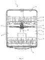
- the Fig. 1 shows a schematic front view of a dishwasher 1.
- the dishwasher 1 is preferably a household dishwasher.
- the dishwasher 1 has a washing container 2, which by means of a in the Fig. 1 not shown door is waterproof closed.
- the washing container 2 is cuboid.
- the washing container 2 has two oppositely disposed side walls 3, 4, a ceiling 5, a cover 5 arranged opposite the bottom 6 and a door opposite positioned rear wall 7.
- the washing container 2 is preferably made of a steel sheet.
- the rinse tank 2 may be at least partially made of a plastic material.
- the bottom 6 may be made of a plastic material.
- the washing container 2 can be arranged in a housing of the dishwasher 1.
- the dishwasher 1 has at least two Spülgutingn 8, 9.
- the Spülguter 8 can be referred to as upper Spülgutage or as upper basket, the Spellerguter 9 can be referred to as lower Spülguta or as a lower basket of the dishwasher 1.
- the Spülgutagen 8, 9 are grid-shaped.
- the Spülgutagen 8, 9 are adapted to receive items to be washed.
- the Spülgutagen 8, 9 are with the help in the Fig. 1 not shown leadership institutions out of the washing compartment 2 out and back in this mobile.
- On the rear wall 7 of the washing container 2, a feed pipe 10 is attached.
- the feed tube 10 is made of a plastic material, for example.
- the feed tube 10 can be snapped with the rear wall 7, clipped, screwed or riveted.
- a in the Fig. 1 not shown pump sump may be provided, to which a heating pump can be connected. With the help of the heating pump, the feed tube 10 can be acted upon with rinsing liquor.
- the supply pipe 10 leads along the rear wall 7 up to the ceiling 5.
- a roof spraying device for distributing the rinsing liquor may be provided.
- a Sprüharman extract 11 is provided between the Sprüharman extract 11 is provided. The Sprüharman extract 11 can be attached to the upper Spülgutage 8 and with this in the washing container 2 into or out of this mobile.
- the spray arm assembly 11 includes an inlet tube 12, which by means of a coupling device is releasably connected to the feed tube 10.
- the Sprüharman extract 11 further comprises a rotatably mounted on the inlet pipe 12 spray arm 13.
- the spray arm 13 may also be referred to as the upper spray arm 13.
- the dishwasher 1 may further include a in the Fig. 1 Not shown lower spray arm, which is arranged under the Spülguta 9.
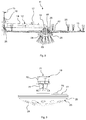
- the Fig. 2 shows the Sprüharman extract 11 in a schematic sectional view.
- the inlet pipe 12 has a slightly inclined from the horizontal tubular base portion 14.
- a coupling device 15 is provided, by means of which the inlet pipe 12 with the feed tube 10 is detachably connectable.
- a snap hook 16 is further provided, which is adapted to lock in the Spülgutation 8, in particular in a wire of Spülgutage 8.
- a hook 17 is also provided on the base portion 14, which is also hooked into the Spülgutability 8.
- the inlet pipe 12 is preferably made of a plastic material.
- the base portion 14 further comprises at one of the coupling means 15 remote from the second end portion on a 90 ° downward in the direction of the bottom 6 curved portion 18 on curvature.
- At the bend portion 18 is in the Fig. 3 shown bearing device 19 attached.
- the bearing device 19 has snap hooks 20 which can be latched to the curved section 18 in the form of a bayonet closure. As a result, the bearing device 19 is rotationally fixed to the curved portion 18.
- the spray arm 13 is rotatably mounted on the bearing device 19.
- the bearing device 19 has an inflow opening 21, through which rinsing water can enter from the inlet pipe 12 into the bearing device 19 and can flow into the spray arm 13 through lateral openings 22.
- the inflow of the wash liquor into the spray arm 13 is in the Fig. 2 represented by arrows.
- the spray arm assembly 11 further comprises a closure device 23 for closing the bearing device 19 on the face side.
- the closure device 23 is preferably made of a plastic material.
- the closure device 23 is fluidically connected to the inlet pipe 12.
- the closure device 23 has at least a spray nozzle 24 on.
- the closure device 23 preferably has a multiplicity of spray nozzles 24.
- the spray nozzles 24 are oriented in the direction of the bottom 6.
- the spray nozzles 24 of the closure device 23 are preferably oriented away from the spray arm 13. In particular, the spray nozzles 24 are oriented in the direction of the Spülgutage 9.
- the spray arm 13 also has top-side spray nozzles 25, which are preferably directed in the direction of the Spülguta 8. Furthermore, the spray arm 13 may have lateral spray nozzles 26, which are adapted to set the spray arm 13 in rotation as soon as it is flowed through by wash liquor.
- the spray arm 13 is arranged between the inlet pipe 12, in particular the curved portion 18 and the closure device 23.
- the closure device 23 is provided on the underside of the spray arm 13.
- the spray arm 13 can furthermore, in addition to the spray nozzles 25, 26 pointing upwards, also have underside spray nozzles, which are oriented in the direction of the bottom 6.
- the closure device 23 has a closure element 27 arranged in a rotationally fixed manner on the inlet pipe 12 and in particular non-rotatably mounted on the bearing device 19 and a spray element 28 rotatable relative to the closure element 27.
- the closure element 27 and the spray element 28 may be firmly connected to each other, so that the spray element 28 is not rotatable relative to the bearing device 19.
- the spray nozzles 24 of the spray element 28 may be oriented to cause the spray element 28 to rotate as flushing fluid passes through the spray nozzles 24.
- the closure element 27 may be rotatable relative to the bearing device 19 together with the spray element 28.
- the closure device 23 may further comprise spray nozzles 29 provided on the closure element 27, which are directed in the direction of the spray arm 13.
- the spray element 28 is in particular dome-shaped.
- the closure device 23 may be removable from the storage device 19.
Landscapes
- Washing And Drying Of Tableware (AREA)
Abstract
Die Erfindung betrifft eine Sprüharmanordnung (11) für eine Geschirrspülmaschine (1), mit einem Sprüharm (13), einem Einlaufrohr (12), an dem der Sprüharm (13) mit Hilfe einer Lagereinrichtung (19) drehbar befestigt ist, und einer Verschlusseinrichtung (23) zum Verschließen der Lagereinrichtung (19), wobei die Verschlusseinrichtung (23) zumindest eine Sprühdüse (24) aufweist.The invention relates to a spray arm arrangement (11) for a dishwasher (1), comprising a spray arm (13), an inlet pipe (12) to which the spray arm (13) is rotatably mounted by means of a bearing device (19), and a closure device (10). 23) for closing the bearing device (19), wherein the closure device (23) has at least one spray nozzle (24).
Description
Die vorliegende Erfindung betrifft eine Sprüharmanordnung für eine Geschirrspülmaschine und eine Geschirrspülmaschine mit einer derartigen Sprüharmanordnung.The present invention relates to a spray arm arrangement for a dishwasher and a dishwasher with such a spray arm arrangement.
Eine Geschirrspülmaschine weist einen Spülbehälter mit in dem Spülbehälter angeordneten Spülgutaufnahmen auf. In dem Spülbehälter kann weiterhin ein Sprüharm vorgesehen sein, der dazu eingerichtet ist, in den Spülgutaufnahmen aufgenommenes Spülgut mit Spülflotte zu beaufschlagen.A dishwasher has a washing container with Spülgutaufnahmen arranged in the washing container. In the rinsing container, a spray arm can furthermore be provided, which is set up to apply rinse liquor accommodated in the items to be washed.
Die
Vor diesem Hintergrund besteht eine Aufgabe der vorliegenden Erfindung darin, eine verbesserte Sprüharmanordnung zur Verfügung zu stellen.Against this background, an object of the present invention is to provide an improved Sprüharmanordnung.
Demgemäß wird eine Sprüharmanordnung für eine Geschirrspülmaschine vorgeschlagen. Die Sprüharmanordnung umfasst einen Sprüharm, ein Einlaufrohr, an dem der Sprüharm mit Hilfe einer Lagereinrichtung drehbar befestigt ist, und eine Verschlusseinrichtung zum Verschließen der Lagereinrichtung, wobei die Verschlusseinrichtung zumindest eine Sprühdüse aufweist.Accordingly, a spray arm arrangement for a dishwasher is proposed. The spray arm assembly comprises a spray arm, an inlet tube to which the spray arm is rotatably mounted by means of a bearing device, and a closure device for closing the bearing device, wherein the closure device has at least one spray nozzle.
Die Verschlusseinrichtung erfüllt eine Doppelfunktion. Dadurch, dass die Verschlusseinrichtung zumindest eine Sprühdüse aufweist, kann diese neben der Verschlussfunktion auch eine Sprühfunktion erfüllen. Insbesondere weist die Geschirrspülmaschine zwei Spülgutaufnahmen zum Aufnehmen von Spülgut auf. Vorzugsweise sind eine untere Spülgutaufnahme oder ein Unterkorb und eine obere Spülgutaufnahme oder ein Oberkorb vorgesehen. Mit Hilfe der Verschlusseinrichtung kann eine verbesserte Reinigungsleistung im Unterkorb erreicht werden. Vorzugsweise weist die Verschlusseinrichtung eine Vielzahl Sprühdüsen auf. Der Sprüharm kann ebenfalls Sprühdüsen aufweisen. Die Sprühdüsen sind vorzugsweise oberseitig an dem Sprüharm vorgesehen und in Richtung des Oberkorbs gerichtet. Zusätzlich kann der Sprüharm unterseitig angeordnete Sprühdüsen aufweisen, die in Richtung des Unterkorbs orientiert sind. Der Sprüharm, das Einlaufrohr, die Lagereinrichtung und/oder die Verschlusseinrichtung können aus einem Kunststoffmaterial gefertigt sein.The closure device fulfills a dual function. Because the closure device has at least one spray nozzle, it can also fulfill a spray function in addition to the closure function. In particular, the dishwasher has two Spülgutaufnahmen for receiving items to be washed. Preferably, a lower Spülgutaufnahme or a lower basket and an upper Spülgutaufnahme or a top basket provided. With the help of the closure device, an improved cleaning performance in the lower basket can be achieved. Preferably, the closure device has a plurality of spray nozzles. The spray arm may also have spray nozzles. The spray nozzles are preferably provided on the upper side of the spray arm and directed in the direction of the upper basket. In addition, the spray arm may have bottom-mounted spray nozzles, which are oriented in the direction of the lower basket. The spray arm, the inlet pipe, the bearing device and / or the closure device can be made of a plastic material.
Gemäß einer Ausführungsform ist die Verschlusseinrichtung mit dem Einlaufrohr verbunden.According to one embodiment, the closure device is connected to the inlet pipe.
Insbesondere ist die Verschlusseinrichtung mit Hilfe der Lagereinrichtung mit dem Einlaufrohr verbunden. Die Lagereinrichtung ist vorzugsweise mit Hilfe eines Bajonettverschlusses mit dem Einlaufrohr gekoppelt. Das Einlaufrohr weist einen Krümmungsabschnitt auf, der in Richtung des Unterkorbs orientiert ist. An dem Krümmungsabschnitt ist die Lagereinrichtung befestigt.In particular, the closure device is connected to the inlet pipe with the aid of the bearing device. The bearing device is preferably coupled to the inlet tube by means of a bayonet closure. The inlet pipe has a curved portion which is oriented in the direction of the lower basket. At the curved portion, the bearing device is attached.
Gemäß einer weiteren Ausführungsform ist der Sprüharm zwischen dem Einlaufrohr und der Verschlusseinrichtung angeordnet.According to a further embodiment, the spray arm is arranged between the inlet pipe and the closure device.
Der Sprüharm ist an der Lagereinrichtung vorzugsweise gleitgelagert. Insbesondere ist die Lagereinrichtung spielbehaftet, so dass der Sprüharm bei einer Drehbewegung gleichzeitig eine Taumelbewegung ausführt. Dies erhöht die Reinigungsleistung.The spray arm is preferably slide-mounted on the bearing device. In particular, the bearing device is subject to play, so that the spray arm simultaneously performs a tumbling motion during a rotational movement. This increases the cleaning performance.
Gemäß einer weiteren Ausführungsform ist die Verschlusseinrichtung unterseitig an dem Sprüharm vorgesehen.According to a further embodiment, the closure device is provided on the underside of the spray arm.
Die Verschlusseinrichtung ist vorzugsweise von der Lagereinrichtung trennbar. Vorzugsweise weist die Verschlusseinrichtung einen größeren Durchmesser auf als die Lagereinrichtung. Hierdurch ist eine günstige Handhabung der Verschlusseinrichtung beim Öffnen der Lagereinrichtung gewährleistet. Die Lagereinrichtung kann zum Austausch des Sprüharms oder zu Reinigungszwecken geöffnet werden.The closure device is preferably separable from the storage device. Preferably, the closure device has a larger diameter than the bearing device. This ensures a favorable handling of the closure device when opening the storage facility. The storage facility can be opened for replacement of the spray arm or for cleaning purposes.
Gemäß einer weiteren Ausführungsform ist die zumindest eine Sprühdüse von dem Sprüharm weg orientiert.According to a further embodiment, the at least one spray nozzle is oriented away from the spray arm.
Insbesondere ist die zumindest eine Sprühdüse in Richtung des Unterkorbs orientiert. Vorzugsweise weist die Verschlusseinrichtung eine Vielzahl Sprühdüsen auf. Eine verbesserte Reinigungsleistung an vorbestimmten Positionen in den Spülgutaufnahmen kann durch definierte starre oder bewegliche Sprühstrahlen erreicht werden.In particular, the at least one spray nozzle is oriented in the direction of the lower basket. Preferably, the closure device has a plurality of spray nozzles. An improved cleaning performance at predetermined positions in the Spülgutaufnahmen can be achieved by defined fixed or movable sprays.
Gemäß einer weiteren Ausführungsform weist die Verschlusseinrichtung ein drehfest an der Lagereinrichtung angeordnetes Verschlusselement und ein relativ zu dem Verschlusselement drehbares Sprühelement auf.In accordance with a further embodiment, the closure device has a closure element arranged rotatably on the bearing device and a spray element rotatable relative to the closure element.
Alternativ kann das Sprühelement drehfest mit dem Verschlusselement verbunden sein. Weiterhin kann das Verschlusselement zusammen mit dem Sprühelement relativ zu der Lagereinrichtung verdrehbar sein.Alternatively, the spray element can be connected in a rotationally fixed manner to the closure element. Furthermore, the closure element can be rotatable together with the spray element relative to the bearing device.
Gemäß einer weiteren Ausführungsform ist die zumindest eine Sprühdüse so angeordnet, dass sie das Sprühelement beim Durchströmen von Spülflotte durch die zumindest eine Sprühdüse in Rotation versetzt.According to a further embodiment, the at least one spray nozzle is arranged so that it sets the spray element in the flow of rinsing fluid through the at least one spray nozzle in rotation.
Vorzugsweise weist die Verschlusseinrichtung eine Vielzahl Sprühdüsen auf, die relativ zueinander unterschiedlich geneigt sind.Preferably, the closure device has a plurality of spray nozzles, which are inclined differently relative to each other.
Gemäß einer weiteren Ausführungsform ist das Sprühelement kuppelförmig.According to a further embodiment, the spray element is dome-shaped.
Insbesondere ist das Sprühelement sphärisch. Das Sprühelement ist vorzugsweise ein dünnwandiges Kunststoffbauteil mit einer Wandstärke zwischen 0,3mm und 3mm.In particular, the spray element is spherical. The spray element is preferably a thin-walled plastic component with a wall thickness between 0.3 mm and 3 mm.
Gemäß einer weiteren Ausführungsform umfasst die Verschlusseinrichtung eine weitere Sprühdüse, die zu dem Sprüharm hin orientiert ist.According to a further embodiment, the closure device comprises a further spray nozzle, which is oriented towards the spray arm.
Vorzugsweise sind an der Verschlusseinrichtung, insbesondere an dem Verschlusselement, mehrere Sprühdüsen vorgesehen, die zu dem Sprüharm hin orientiert sind. Hierdurch wird die Reinigungsleistung in dem Oberkorb verbessert.Preferably, a plurality of spray nozzles are provided on the closure device, in particular on the closure element, which are oriented towards the spray arm. As a result, the cleaning performance is improved in the upper basket.
Weiterhin wird eine Geschirrspülmaschine mit einer derartigen Sprüharmanordnung vorgeschlagen.Furthermore, a dishwasher is proposed with such Sprüharmanordnung.
Die Geschirrspülmaschine ist vorzugsweise eine Haushalts-Geschirrspülmaschine. Die Geschirrspülmaschine kann einen Spülbehälter aufweisen, in dem die Spülgutaufnahmen angeordnet sind. Vorzugsweise sind in dem Spülbehälter zwei Spülgutaufnahmen, insbesondere der Oberkorb und der Unterkorb, angeordnet. Die Sprüharmanordnung ist vorzugsweise zwischen den Spülgutaufnahmen angeordnet. Insbesondere kann die Sprüharmanordnung an dem Oberkorb eingehängt sein.The dishwasher is preferably a household dishwasher. The dishwasher may have a washing container, in which the Spülgutaufnahmen are arranged. Preferably two Spülgutaufnahmen, in particular the upper basket and the lower basket are arranged in the washing. The Sprüharmanordnung is preferably arranged between the Spülgutaufnahmen. In particular, the Sprüharmanordnung can be mounted on the upper basket.
Weitere mögliche Implementierungen der Sprüharmanordnung und/oder der Geschirrspülmaschine umfassen auch nicht explizit genannte Kombinationen von zuvor oder im Folgenden bezüglich der Ausführungsbeispiele beschriebenen Merkmale oder Ausführungsformen. Dabei wird der Fachmann auch Einzelaspekte als Verbesserungen oder Ergänzungen zu der jeweiligen Grundform der Sprüharmanordnung und/oder der Geschirrspülmaschine hinzufügen.Further possible implementations of the spray arm arrangement and / or the dishwasher also include not explicitly mentioned combinations of features or embodiments described above or below with regard to the exemplary embodiments. The person skilled in the art will also add individual aspects as improvements or additions to the respective basic form of the spray arm arrangement and / or the dishwasher.
Weitere vorteilhafte Ausgestaltungen und Aspekte der Sprüharmanordnung und/oder der Geschirrspülmaschine sind Gegenstand der Unteransprüche sowie der im Folgenden beschriebenen Ausführungsbeispiele der Sprüharmanordnung und/oder der Geschirrspülmaschine. Im Weiteren werden die Sprüharmanordnung und/oder die Geschirrspülmaschine anhand von bevorzugten Ausführungsformen unter Bezugnahme auf die beigelegten Figuren näher erläutert.
-
Fig. 1 zeigt eine schematische Vorderansicht einer Ausführungsform einer Geschirrspülmaschine; -
Fig. 2 zeigt eine schematische Schnittansicht einer Ausführungsform einer Sprüharmanordnung für die Geschirrspülmaschine gemäßFig. 1 ; und -
Fig. 3 zeigt eine schematische Seitenansicht einer Ausführungsform einer Lagereinrichtung für die Sprüharmanordnung gemäßFig. 2 .
-
Fig. 1 shows a schematic front view of an embodiment of a dishwasher; -
Fig. 2 shows a schematic sectional view of an embodiment of a Sprüharmanordnung for the dishwasher according toFig. 1 ; and -
Fig. 3 shows a schematic side view of an embodiment of a storage device for the Sprüharmanordnung according toFig. 2 ,
In den Figuren sind gleiche oder funktionsgleiche Elemente mit denselben Bezugszeichen versehen worden, sofern nichts anderes angegeben ist.In the figures, the same or functionally identical elements have been given the same reference numerals, unless stated otherwise.
Die
Die Geschirrspülmaschine 1 weist zumindest zwei Spülgutaufnahmen 8, 9 auf. Die Spülgutaufnahme 8 kann als obere Spülgutaufnahme oder als Oberkorb, die Spülgutaufnahme 9 kann als untere Spülgutaufnahme oder als Unterkorb der Geschirrspülmaschine 1 bezeichnet werden. Die Spülgutaufnahmen 8, 9 sind gitterförmig. Die Spülgutaufnahmen 8, 9 sind dazu eingerichtet, Spülgut aufzunehmen. Die Spülgutaufnahmen 8, 9 sind mit Hilfe in der
Das Zuführrohr 10 kann mit der Rückwand 7 verschnappt, verclipst, verschraubt oder vernietet sein. An dem Boden 6 kann ein in der
Die
Die Lagereinrichtung 19 weist Schnapphaken 20 auf, die mit dem Krümmungsabschnitt 18 in Form eines Bajonettverschlusses verrastbar sind. Hierdurch ist die Lagereinrichtung 19 verdrehfest an dem Krümmungsabschnitt 18 festgelegt. Der Sprüharm 13 ist drehbar an der Lagereinrichtung 19 gelagert. Die Lagereinrichtung 19 weist eine Einströmöffnung 21 auf, durch die Spülflotte von dem Einlaufrohr 12 in die Lagereinrichtung 19 eintreten und durch seitliche Öffnungen 22 in den Sprüharm 13 hineinströmen kann.The bearing
Das Einströmen der Spülflotte in den Sprüharm 13 ist in der
Der Sprüharm 13 ist zwischen dem Einlaufrohr 12, insbesondere dem Krümmungsabschnitt 18 und der Verschlusseinrichtung 23 angeordnet. Insbesondere ist die Verschlusseinrichtung 23 unterseitig an dem Sprüharm 13 vorgesehen. Der Sprüharm 13 kann weiterhin zusätzlich zu den nach oben gerichteten Sprühdüsen 25, 26 auch unterseitige Sprühdüsen aufweisen, die in Richtung des Bodens 6 orientiert sind. Die Verschlusseinrichtung 23 weist ein drehfest an dem Einlaufrohr 12 und insbesondere drehfest an der Lagereinrichtung 19 angeordnetes Verschlusselement 27 und ein relativ zu dem Verschlusselement 27 drehbares Sprühelement 28 auf.The
Alternativ können das Verschlusselement 27 und das Sprühelement 28 fest miteinander verbunden sein, so dass das Sprühelement 28 nicht rotierbar gegenüber der Lagereinrichtung 19 ist. Insbesondere können die Sprühdüsen 24 des Sprühelements 28 so orientiert sein, dass diese das Sprühelement 28 in Rotation versetzen, sobald Spülflotte durch die Sprühdüsen 24 strömt. Optional kann das Verschlusselement 27 zusammen mit dem Sprühelement 28 relativ zu der Lagereinrichtung 19 verdrehbar sein. Die Verschlusseinrichtung 23 kann weiterhin an dem Verschlusselement 27 vorgesehene Sprühdüsen 29 aufweisen, die in Richtung des Sprüharms 13 gerichtet sind. Das Sprühelement 28 ist insbesondere kuppelförmig. Die Verschlusseinrichtung 23 kann von der Lagereinrichtung 19 abnehmbar sein.Alternatively, the
Vom Einlaufrohr 12 wird Spülflotte in den Sprüharm 13 und in die Verschlusseinrichtung 23 geleitet. Hierdurch wird nicht nur über den Sprüharm 13 das Spülgut in der oberen Spülgutaufnahme 8 gereinigt, sondern es erfolgt auch eine zusätzliche Reinigung des Spülguts in der unteren Spülgutaufnahme 9 mit Hilfe des in der Verschlusseinrichtung 23 integrierten Sprühelements 28. Hierdurch erhält die Verschlusseinrichtung 23 eine Doppelfunktion. Zum einen hält die Verschlusseinrichtung 23 den Sprüharm 13 an der Lagereinrichtung 19, zum anderen weist die Verschlusseinrichtung 23 eine Sprühfunktion auf. Hierdurch kann die Reinigungsleistung in der unteren Spülgutaufnahme 9 verbessert werden. Die Reinigungsleistung kann weiterhin dadurch verbessert werden, dass definierte starre oder bewegliche Sprühstrahlen vorgesehen werden. Durch die Größe der Verschlusseinrichtung 23 kann diese einfach von der Sprüharmanordnung 11 abgezogen werden, um den Sprüharm 13 auszuwechseln.From the
Obwohl die vorliegende Erfindung anhand von Ausführungsbeispielen beschrieben wurde, ist sie vielfältig modifizierbar.Although the present invention has been described with reference to embodiments, it is variously modifiable.
- 11
- Geschirrspülmaschinedishwasher
- 22
- Spülbehälterrinse tank
- 33
- SeitenwandSide wall
- 44
- SeitenwandSide wall
- 55
- Deckeblanket
- 66
- Bodenground
- 77
- Rückwandrear wall
- 88th
- SpülgutaufnahmeSpülgutaufnahme
- 99
- SpülgutaufnahmeSpülgutaufnahme
- 1010
- Zuführrohrfeed
- 1111
- Sprüharmanordnungspray arm
- 1212
- Einlaufrohrinlet pipe
- 1313
- Sprüharmspray arm
- 1414
- Basisabschnittbase section
- 1515
- Kupplungseinrichtungcoupling device
- 1616
- Schnapphakensnap hooks
- 1717
- Hakenhook
- 1818
- Krümmungsabschnittcurved section
- 1919
- LagereinrichtungStorage facility
- 2020
- Schnapphakensnap hooks
- 2121
- Einströmöffnunginflow
- 2222
- Öffnungopening
- 2323
- Verschlusseinrichtungclosure device
- 2424
- Sprühdüsespray nozzle
- 2525
- Sprühdüsespray nozzle
- 2626
- Sprühdüsespray nozzle
- 2727
- Verschlusselementclosure element
- 2828
- Sprühelementspraying
- 2929
- Sprühdüsespray nozzle
Claims (10)
Priority Applications (1)
| Application Number | Priority Date | Filing Date | Title |
|---|---|---|---|
| PL16162734T PL3085293T3 (en) | 2015-04-24 | 2016-03-30 | Spray arm assembly and dishwasher |
Applications Claiming Priority (1)
| Application Number | Priority Date | Filing Date | Title |
|---|---|---|---|
| DE102015207588.5A DE102015207588A1 (en) | 2015-04-24 | 2015-04-24 | Spray arm assembly and dishwasher |
Publications (2)
| Publication Number | Publication Date |
|---|---|
| EP3085293A1 true EP3085293A1 (en) | 2016-10-26 |
| EP3085293B1 EP3085293B1 (en) | 2019-08-07 |
Family
ID=55640629
Family Applications (1)
| Application Number | Title | Priority Date | Filing Date |
|---|---|---|---|
| EP16162734.4A Active EP3085293B1 (en) | 2015-04-24 | 2016-03-30 | Spray arm assembly and dishwasher |
Country Status (3)
| Country | Link |
|---|---|
| EP (1) | EP3085293B1 (en) |
| DE (1) | DE102015207588A1 (en) |
| PL (1) | PL3085293T3 (en) |
Cited By (6)
| Publication number | Priority date | Publication date | Assignee | Title |
|---|---|---|---|---|
| CN111163673A (en) * | 2017-09-29 | 2020-05-15 | Bsh家用电器有限公司 | household dishwasher |
| CN112040828A (en) * | 2018-04-26 | 2020-12-04 | Bsh家用电器有限公司 | Domestic dishwasher with a spray device |
| US11026555B2 (en) | 2015-12-21 | 2021-06-08 | Electrolux Appliances Aktiebolag | Dishwasher comprising a wash arm arrangement |
| US11389043B2 (en) | 2017-10-31 | 2022-07-19 | Electrolux Appliances Aktiebolag | Dishwasher spray arm assembly |
| US11464391B2 (en) | 2017-10-31 | 2022-10-11 | Electrolux Appliances Aktiebolag | Spray arm assembly |
| US11612299B2 (en) | 2017-10-31 | 2023-03-28 | Electrolux Appliances Aktiebolag | Wash arm assembly |
Families Citing this family (4)
| Publication number | Priority date | Publication date | Assignee | Title |
|---|---|---|---|---|
| PL3481269T3 (en) | 2016-07-08 | 2021-09-13 | Electrolux Appliances Aktiebolag | Wash arm assembly |
| DE102022207320A1 (en) * | 2022-07-18 | 2024-01-18 | BSH Hausgeräte GmbH | Dishwasher and washware holder with expansion option |
| DE102024206777A1 (en) * | 2024-07-18 | 2026-01-22 | BSH Hausgeräte GmbH | dishwasher |
| DE102024208439A1 (en) * | 2024-09-05 | 2026-03-05 | BSH Hausgeräte GmbH | Dishwashing tray with support geometry for offset placement of dishes |
Citations (7)
| Publication number | Priority date | Publication date | Assignee | Title |
|---|---|---|---|---|
| DE1628625A1 (en) * | 1965-07-26 | 1970-08-20 | Hobart Mfg Co | Liquid distribution system for dishwashers |
| US3538927A (en) * | 1967-04-27 | 1970-11-10 | Electrolux Ab | Dishwashing machine |
| JPS59103640A (en) * | 1983-11-10 | 1984-06-15 | 松下電器産業株式会社 | Tablewear washer |
| DE29509724U1 (en) * | 1994-06-16 | 1995-08-24 | Zanussi Elettrodomestici S.P.A., Pordenone | Dishwasher with rotating spray wing |
| DE19642911A1 (en) | 1996-10-17 | 1998-04-23 | Bosch Siemens Hausgeraete | Dishwashing machine spray arm mounting |
| EP2067428A2 (en) * | 2007-12-05 | 2009-06-10 | Premark FEG L.L.C. | Improved washing and/or rinsing device, and dishwashing machine featuring such a device |
| EP2710945A1 (en) * | 2012-09-19 | 2014-03-26 | LG Electronics, Inc. | Dishwashing machine |
Family Cites Families (1)
| Publication number | Priority date | Publication date | Assignee | Title |
|---|---|---|---|---|
| US4884585A (en) * | 1988-10-21 | 1989-12-05 | Oh Yang H | Rotary sprayer for an automatic dishwasher |
-
2015
- 2015-04-24 DE DE102015207588.5A patent/DE102015207588A1/en not_active Withdrawn
-
2016
- 2016-03-30 PL PL16162734T patent/PL3085293T3/en unknown
- 2016-03-30 EP EP16162734.4A patent/EP3085293B1/en active Active
Patent Citations (7)
| Publication number | Priority date | Publication date | Assignee | Title |
|---|---|---|---|---|
| DE1628625A1 (en) * | 1965-07-26 | 1970-08-20 | Hobart Mfg Co | Liquid distribution system for dishwashers |
| US3538927A (en) * | 1967-04-27 | 1970-11-10 | Electrolux Ab | Dishwashing machine |
| JPS59103640A (en) * | 1983-11-10 | 1984-06-15 | 松下電器産業株式会社 | Tablewear washer |
| DE29509724U1 (en) * | 1994-06-16 | 1995-08-24 | Zanussi Elettrodomestici S.P.A., Pordenone | Dishwasher with rotating spray wing |
| DE19642911A1 (en) | 1996-10-17 | 1998-04-23 | Bosch Siemens Hausgeraete | Dishwashing machine spray arm mounting |
| EP2067428A2 (en) * | 2007-12-05 | 2009-06-10 | Premark FEG L.L.C. | Improved washing and/or rinsing device, and dishwashing machine featuring such a device |
| EP2710945A1 (en) * | 2012-09-19 | 2014-03-26 | LG Electronics, Inc. | Dishwashing machine |
Cited By (7)
| Publication number | Priority date | Publication date | Assignee | Title |
|---|---|---|---|---|
| US11026555B2 (en) | 2015-12-21 | 2021-06-08 | Electrolux Appliances Aktiebolag | Dishwasher comprising a wash arm arrangement |
| CN111163673A (en) * | 2017-09-29 | 2020-05-15 | Bsh家用电器有限公司 | household dishwasher |
| US11389043B2 (en) | 2017-10-31 | 2022-07-19 | Electrolux Appliances Aktiebolag | Dishwasher spray arm assembly |
| US11464391B2 (en) | 2017-10-31 | 2022-10-11 | Electrolux Appliances Aktiebolag | Spray arm assembly |
| US11612299B2 (en) | 2017-10-31 | 2023-03-28 | Electrolux Appliances Aktiebolag | Wash arm assembly |
| CN112040828A (en) * | 2018-04-26 | 2020-12-04 | Bsh家用电器有限公司 | Domestic dishwasher with a spray device |
| CN112040828B (en) * | 2018-04-26 | 2024-04-19 | Bsh家用电器有限公司 | Household dishwasher with spraying device |
Also Published As
| Publication number | Publication date |
|---|---|
| DE102015207588A1 (en) | 2016-10-27 |
| PL3085293T3 (en) | 2020-01-31 |
| EP3085293B1 (en) | 2019-08-07 |
Similar Documents
| Publication | Publication Date | Title |
|---|---|---|
| EP3085293B1 (en) | Spray arm assembly and dishwasher | |
| EP3285632B1 (en) | Spray arm and dishwasher | |
| EP1708608B1 (en) | Crockery basket for a dishwasher machine, comprising an intensive washing zone | |
| DE102012217568B4 (en) | dishwasher | |
| WO2000012942A1 (en) | Method for cleaning a cooking appliance and corresponding device | |
| EP2601877B1 (en) | Dishwasher with automatic reversal of the direction of rotation of the spray arm | |
| DE2410733A1 (en) | WINDOW WASHER | |
| DE1428320A1 (en) | Dish washing machine | |
| EP4003127B1 (en) | Domestic dishwasher | |
| DE1503785A1 (en) | Dishwasher | |
| DE102004018878B4 (en) | Dishwasher with a washing container in which at least one spray arm is arranged | |
| DE102010043021B4 (en) | Dishwasher, in particular household dishwasher | |
| WO2006069827A1 (en) | Dishwasher provided with deflecting screens | |
| EP2901908B1 (en) | Filter assembly, wash tub and water-bearing household device | |
| DE102014100318B4 (en) | dishwasher | |
| DE102017105589B4 (en) | Spraying device for a dishwasher | |
| EP1382287B1 (en) | Spraying device for an automatic dishwasher | |
| DE102008025207A1 (en) | Dishwasher for cleaning e.g. saucepans, has steam device with steam nozzle formed as recoiling wheel, jet pipe and plate that include steam exit openings distributed over pipe and/or plate | |
| DE102019211400B3 (en) | Household dishwasher | |
| EP3897334B1 (en) | Domestic dishwasher | |
| DE1628737A1 (en) | Hatch for dishwashers or dishwashers | |
| DE102008010057B4 (en) | Cleaning machine for butcher equipment | |
| DE363621C (en) | Liquid distributors, especially for dishwashers | |
| DE102007051100A1 (en) | Washing device for drinking glass i.e. beer glass, has washing container and rinsing system provided with respective direct outlets either for cold water or for warm water with temperature of preset degree Celsius | |
| DE1957141A1 (en) | Spray device for dishwashers |
Legal Events
| Date | Code | Title | Description |
|---|---|---|---|
| PUAI | Public reference made under article 153(3) epc to a published international application that has entered the european phase |
Free format text: ORIGINAL CODE: 0009012 |
|
| AK | Designated contracting states |
Kind code of ref document: A1 Designated state(s): AL AT BE BG CH CY CZ DE DK EE ES FI FR GB GR HR HU IE IS IT LI LT LU LV MC MK MT NL NO PL PT RO RS SE SI SK SM TR |
|
| AX | Request for extension of the european patent |
Extension state: BA ME |
|
| 17P | Request for examination filed |
Effective date: 20170426 |
|
| RBV | Designated contracting states (corrected) |
Designated state(s): AL AT BE BG CH CY CZ DE DK EE ES FI FR GB GR HR HU IE IS IT LI LT LU LV MC MK MT NL NO PL PT RO RS SE SI SK SM TR |
|
| STAA | Information on the status of an ep patent application or granted ep patent |
Free format text: STATUS: REQUEST FOR EXAMINATION WAS MADE |
|
| GRAP | Despatch of communication of intention to grant a patent |
Free format text: ORIGINAL CODE: EPIDOSNIGR1 |
|
| STAA | Information on the status of an ep patent application or granted ep patent |
Free format text: STATUS: GRANT OF PATENT IS INTENDED |
|
| INTG | Intention to grant announced |
Effective date: 20190228 |
|
| GRAS | Grant fee paid |
Free format text: ORIGINAL CODE: EPIDOSNIGR3 |
|
| GRAA | (expected) grant |
Free format text: ORIGINAL CODE: 0009210 |
|
| STAA | Information on the status of an ep patent application or granted ep patent |
Free format text: STATUS: THE PATENT HAS BEEN GRANTED |
|
| AK | Designated contracting states |
Kind code of ref document: B1 Designated state(s): AL AT BE BG CH CY CZ DE DK EE ES FI FR GB GR HR HU IE IS IT LI LT LU LV MC MK MT NL NO PL PT RO RS SE SI SK SM TR |
|
| REG | Reference to a national code |
Ref country code: GB Ref legal event code: FG4D Free format text: NOT ENGLISH |
|
| REG | Reference to a national code |
Ref country code: CH Ref legal event code: EP Ref country code: AT Ref legal event code: REF Ref document number: 1162557 Country of ref document: AT Kind code of ref document: T Effective date: 20190815 |
|
| REG | Reference to a national code |
Ref country code: DE Ref legal event code: R096 Ref document number: 502016005864 Country of ref document: DE |
|
| REG | Reference to a national code |
Ref country code: IE Ref legal event code: FG4D Free format text: LANGUAGE OF EP DOCUMENT: GERMAN |
|
| REG | Reference to a national code |
Ref country code: NL Ref legal event code: MP Effective date: 20190807 |
|
| REG | Reference to a national code |
Ref country code: LT Ref legal event code: MG4D |
|
| PG25 | Lapsed in a contracting state [announced via postgrant information from national office to epo] |
Ref country code: FI Free format text: LAPSE BECAUSE OF FAILURE TO SUBMIT A TRANSLATION OF THE DESCRIPTION OR TO PAY THE FEE WITHIN THE PRESCRIBED TIME-LIMIT Effective date: 20190807 Ref country code: HR Free format text: LAPSE BECAUSE OF FAILURE TO SUBMIT A TRANSLATION OF THE DESCRIPTION OR TO PAY THE FEE WITHIN THE PRESCRIBED TIME-LIMIT Effective date: 20190807 Ref country code: PT Free format text: LAPSE BECAUSE OF FAILURE TO SUBMIT A TRANSLATION OF THE DESCRIPTION OR TO PAY THE FEE WITHIN THE PRESCRIBED TIME-LIMIT Effective date: 20191209 Ref country code: SE Free format text: LAPSE BECAUSE OF FAILURE TO SUBMIT A TRANSLATION OF THE DESCRIPTION OR TO PAY THE FEE WITHIN THE PRESCRIBED TIME-LIMIT Effective date: 20190807 Ref country code: NO Free format text: LAPSE BECAUSE OF FAILURE TO SUBMIT A TRANSLATION OF THE DESCRIPTION OR TO PAY THE FEE WITHIN THE PRESCRIBED TIME-LIMIT Effective date: 20191107 Ref country code: BG Free format text: LAPSE BECAUSE OF FAILURE TO SUBMIT A TRANSLATION OF THE DESCRIPTION OR TO PAY THE FEE WITHIN THE PRESCRIBED TIME-LIMIT Effective date: 20191107 Ref country code: NL Free format text: LAPSE BECAUSE OF FAILURE TO SUBMIT A TRANSLATION OF THE DESCRIPTION OR TO PAY THE FEE WITHIN THE PRESCRIBED TIME-LIMIT Effective date: 20190807 Ref country code: LT Free format text: LAPSE BECAUSE OF FAILURE TO SUBMIT A TRANSLATION OF THE DESCRIPTION OR TO PAY THE FEE WITHIN THE PRESCRIBED TIME-LIMIT Effective date: 20190807 |
|
| PG25 | Lapsed in a contracting state [announced via postgrant information from national office to epo] |
Ref country code: GR Free format text: LAPSE BECAUSE OF FAILURE TO SUBMIT A TRANSLATION OF THE DESCRIPTION OR TO PAY THE FEE WITHIN THE PRESCRIBED TIME-LIMIT Effective date: 20191108 Ref country code: ES Free format text: LAPSE BECAUSE OF FAILURE TO SUBMIT A TRANSLATION OF THE DESCRIPTION OR TO PAY THE FEE WITHIN THE PRESCRIBED TIME-LIMIT Effective date: 20190807 Ref country code: LV Free format text: LAPSE BECAUSE OF FAILURE TO SUBMIT A TRANSLATION OF THE DESCRIPTION OR TO PAY THE FEE WITHIN THE PRESCRIBED TIME-LIMIT Effective date: 20190807 Ref country code: AL Free format text: LAPSE BECAUSE OF FAILURE TO SUBMIT A TRANSLATION OF THE DESCRIPTION OR TO PAY THE FEE WITHIN THE PRESCRIBED TIME-LIMIT Effective date: 20190807 Ref country code: RS Free format text: LAPSE BECAUSE OF FAILURE TO SUBMIT A TRANSLATION OF THE DESCRIPTION OR TO PAY THE FEE WITHIN THE PRESCRIBED TIME-LIMIT Effective date: 20190807 Ref country code: IS Free format text: LAPSE BECAUSE OF FAILURE TO SUBMIT A TRANSLATION OF THE DESCRIPTION OR TO PAY THE FEE WITHIN THE PRESCRIBED TIME-LIMIT Effective date: 20191207 |
|
| PG25 | Lapsed in a contracting state [announced via postgrant information from national office to epo] |
Ref country code: EE Free format text: LAPSE BECAUSE OF FAILURE TO SUBMIT A TRANSLATION OF THE DESCRIPTION OR TO PAY THE FEE WITHIN THE PRESCRIBED TIME-LIMIT Effective date: 20190807 Ref country code: RO Free format text: LAPSE BECAUSE OF FAILURE TO SUBMIT A TRANSLATION OF THE DESCRIPTION OR TO PAY THE FEE WITHIN THE PRESCRIBED TIME-LIMIT Effective date: 20190807 Ref country code: IT Free format text: LAPSE BECAUSE OF FAILURE TO SUBMIT A TRANSLATION OF THE DESCRIPTION OR TO PAY THE FEE WITHIN THE PRESCRIBED TIME-LIMIT Effective date: 20190807 Ref country code: DK Free format text: LAPSE BECAUSE OF FAILURE TO SUBMIT A TRANSLATION OF THE DESCRIPTION OR TO PAY THE FEE WITHIN THE PRESCRIBED TIME-LIMIT Effective date: 20190807 |
|
| PG25 | Lapsed in a contracting state [announced via postgrant information from national office to epo] |
Ref country code: SK Free format text: LAPSE BECAUSE OF FAILURE TO SUBMIT A TRANSLATION OF THE DESCRIPTION OR TO PAY THE FEE WITHIN THE PRESCRIBED TIME-LIMIT Effective date: 20190807 Ref country code: CZ Free format text: LAPSE BECAUSE OF FAILURE TO SUBMIT A TRANSLATION OF THE DESCRIPTION OR TO PAY THE FEE WITHIN THE PRESCRIBED TIME-LIMIT Effective date: 20190807 Ref country code: IS Free format text: LAPSE BECAUSE OF FAILURE TO SUBMIT A TRANSLATION OF THE DESCRIPTION OR TO PAY THE FEE WITHIN THE PRESCRIBED TIME-LIMIT Effective date: 20200224 Ref country code: SM Free format text: LAPSE BECAUSE OF FAILURE TO SUBMIT A TRANSLATION OF THE DESCRIPTION OR TO PAY THE FEE WITHIN THE PRESCRIBED TIME-LIMIT Effective date: 20190807 |
|
| REG | Reference to a national code |
Ref country code: DE Ref legal event code: R097 Ref document number: 502016005864 Country of ref document: DE |
|
| PLBE | No opposition filed within time limit |
Free format text: ORIGINAL CODE: 0009261 |
|
| STAA | Information on the status of an ep patent application or granted ep patent |
Free format text: STATUS: NO OPPOSITION FILED WITHIN TIME LIMIT |
|
| PG2D | Information on lapse in contracting state deleted |
Ref country code: IS |
|
| 26N | No opposition filed |
Effective date: 20200603 |
|
| PG25 | Lapsed in a contracting state [announced via postgrant information from national office to epo] |
Ref country code: SI Free format text: LAPSE BECAUSE OF FAILURE TO SUBMIT A TRANSLATION OF THE DESCRIPTION OR TO PAY THE FEE WITHIN THE PRESCRIBED TIME-LIMIT Effective date: 20190807 |
|
| PG25 | Lapsed in a contracting state [announced via postgrant information from national office to epo] |
Ref country code: MC Free format text: LAPSE BECAUSE OF FAILURE TO SUBMIT A TRANSLATION OF THE DESCRIPTION OR TO PAY THE FEE WITHIN THE PRESCRIBED TIME-LIMIT Effective date: 20190807 |
|
| REG | Reference to a national code |
Ref country code: CH Ref legal event code: PL |
|
| REG | Reference to a national code |
Ref country code: BE Ref legal event code: MM Effective date: 20200331 |
|
| PG25 | Lapsed in a contracting state [announced via postgrant information from national office to epo] |
Ref country code: LU Free format text: LAPSE BECAUSE OF NON-PAYMENT OF DUE FEES Effective date: 20200330 |
|
| PG25 | Lapsed in a contracting state [announced via postgrant information from national office to epo] |
Ref country code: FR Free format text: LAPSE BECAUSE OF NON-PAYMENT OF DUE FEES Effective date: 20200331 Ref country code: LI Free format text: LAPSE BECAUSE OF NON-PAYMENT OF DUE FEES Effective date: 20200331 Ref country code: IE Free format text: LAPSE BECAUSE OF NON-PAYMENT OF DUE FEES Effective date: 20200330 Ref country code: CH Free format text: LAPSE BECAUSE OF NON-PAYMENT OF DUE FEES Effective date: 20200331 |
|
| PG25 | Lapsed in a contracting state [announced via postgrant information from national office to epo] |
Ref country code: BE Free format text: LAPSE BECAUSE OF NON-PAYMENT OF DUE FEES Effective date: 20200331 |
|
| GBPC | Gb: european patent ceased through non-payment of renewal fee |
Effective date: 20200330 |
|
| PG25 | Lapsed in a contracting state [announced via postgrant information from national office to epo] |
Ref country code: GB Free format text: LAPSE BECAUSE OF NON-PAYMENT OF DUE FEES Effective date: 20200330 |
|
| REG | Reference to a national code |
Ref country code: AT Ref legal event code: MM01 Ref document number: 1162557 Country of ref document: AT Kind code of ref document: T Effective date: 20210330 |
|
| PG25 | Lapsed in a contracting state [announced via postgrant information from national office to epo] |
Ref country code: MT Free format text: LAPSE BECAUSE OF FAILURE TO SUBMIT A TRANSLATION OF THE DESCRIPTION OR TO PAY THE FEE WITHIN THE PRESCRIBED TIME-LIMIT Effective date: 20190807 Ref country code: CY Free format text: LAPSE BECAUSE OF FAILURE TO SUBMIT A TRANSLATION OF THE DESCRIPTION OR TO PAY THE FEE WITHIN THE PRESCRIBED TIME-LIMIT Effective date: 20190807 |
|
| PG25 | Lapsed in a contracting state [announced via postgrant information from national office to epo] |
Ref country code: MK Free format text: LAPSE BECAUSE OF FAILURE TO SUBMIT A TRANSLATION OF THE DESCRIPTION OR TO PAY THE FEE WITHIN THE PRESCRIBED TIME-LIMIT Effective date: 20190807 |
|
| PG25 | Lapsed in a contracting state [announced via postgrant information from national office to epo] |
Ref country code: AT Free format text: LAPSE BECAUSE OF NON-PAYMENT OF DUE FEES Effective date: 20210330 |
|
| PGFP | Annual fee paid to national office [announced via postgrant information from national office to epo] |
Ref country code: DE Payment date: 20250331 Year of fee payment: 10 |
|
| PGFP | Annual fee paid to national office [announced via postgrant information from national office to epo] |
Ref country code: PL Payment date: 20250318 Year of fee payment: 10 |
|
| PGFP | Annual fee paid to national office [announced via postgrant information from national office to epo] |
Ref country code: TR Payment date: 20250321 Year of fee payment: 10 |