EP2601877B1 - Dishwasher with automatic reversal of the direction of rotation of the spray arm - Google Patents
Dishwasher with automatic reversal of the direction of rotation of the spray arm Download PDFInfo
- Publication number
- EP2601877B1 EP2601877B1 EP12401244.4A EP12401244A EP2601877B1 EP 2601877 B1 EP2601877 B1 EP 2601877B1 EP 12401244 A EP12401244 A EP 12401244A EP 2601877 B1 EP2601877 B1 EP 2601877B1
- Authority
- EP
- European Patent Office
- Prior art keywords
- spray arm
- distribution device
- distribution
- distribution chamber
- spray
- Prior art date
- Legal status (The legal status is an assumption and is not a legal conclusion. Google has not performed a legal analysis and makes no representation as to the accuracy of the status listed.)
- Active
Links
- 239000007921 spray Substances 0.000 title claims description 102
- 238000005406 washing Methods 0.000 claims description 18
- 230000006835 compression Effects 0.000 claims description 4
- 238000007906 compression Methods 0.000 claims description 4
- 239000012530 fluid Substances 0.000 description 7
- 230000008859 change Effects 0.000 description 6
- 239000007788 liquid Substances 0.000 description 5
- XLYOFNOQVPJJNP-UHFFFAOYSA-N water Substances O XLYOFNOQVPJJNP-UHFFFAOYSA-N 0.000 description 5
- 238000010276 construction Methods 0.000 description 3
- 238000004851 dishwashing Methods 0.000 description 3
- 238000004140 cleaning Methods 0.000 description 2
- 238000011010 flushing procedure Methods 0.000 description 2
- 239000008237 rinsing water Substances 0.000 description 2
- 238000005507 spraying Methods 0.000 description 2
- 230000009471 action Effects 0.000 description 1
- 230000004913 activation Effects 0.000 description 1
- 230000000994 depressogenic effect Effects 0.000 description 1
- 210000003746 feather Anatomy 0.000 description 1
- 230000006872 improvement Effects 0.000 description 1
Images


Classifications
-
- A—HUMAN NECESSITIES
- A47—FURNITURE; DOMESTIC ARTICLES OR APPLIANCES; COFFEE MILLS; SPICE MILLS; SUCTION CLEANERS IN GENERAL
- A47L—DOMESTIC WASHING OR CLEANING; SUCTION CLEANERS IN GENERAL
- A47L15/00—Washing or rinsing machines for crockery or tableware
- A47L15/14—Washing or rinsing machines for crockery or tableware with stationary crockery baskets and spraying devices within the cleaning chamber
- A47L15/18—Washing or rinsing machines for crockery or tableware with stationary crockery baskets and spraying devices within the cleaning chamber with movably-mounted spraying devices
- A47L15/22—Rotary spraying devices
- A47L15/23—Rotary spraying devices moved by means of the sprays
-
- A—HUMAN NECESSITIES
- A47—FURNITURE; DOMESTIC ARTICLES OR APPLIANCES; COFFEE MILLS; SPICE MILLS; SUCTION CLEANERS IN GENERAL
- A47L—DOMESTIC WASHING OR CLEANING; SUCTION CLEANERS IN GENERAL
- A47L15/00—Washing or rinsing machines for crockery or tableware
- A47L15/42—Details
- A47L15/4278—Nozzles
- A47L15/4282—Arrangements to change or modify spray pattern or direction
Definitions
- the invention relates to a dishwasher having a washing compartment and a spray system provided in the washing compartment, which has a rotatably mounted spray arm, wherein the spray arm drive nozzles, which drive nozzles serve a rotary drive of the spray arm in the left direction on the one hand and in the right direction on the other.
- Dishwashers of the type mentioned are known from the prior art per se. A separate documentary proof is therefore not required at this point.
- Generic dishwashers have a Spülbottich, which in turn provides a Spülraum.
- the washing compartment is accessible via an opening in the washing tub, which opening can be closed in a fluid-tight manner by means of a door pivotably arranged on the washing tub.
- the washing compartment of the dishwasher serves to receive items to be cleaned. This is applied as part of a designated Spülprogrammablaufs by means of rinsing liquid, the so-called wash liquor.
- a dishwashing machine has a spray system provided in the washing compartment for loading items to be cleaned with washing liquor.
- a spray system typically has at least one rotatably mounted spray arm.
- several such spray arms are provided, and depending on the design of the dishwasher two or three spray arms are common practice.
- Each spray arm is connected to a supply line for rinsing liquor.
- rinsing liquor passes through this supply line to the spray arm, via which the rinsing liquor is discharged in the direction of the items to be cleaned.
- the rinsing liquor emitted by the spray arm collects in the washing compartment and is guided in an open flow circuit for a renewed spraying of the dishes.
- a circulation pump is used, which continuously circulates the rinsing liquor during a proper program implementation.
- not all the spray arms are used at the same time in a designated program sequence. It is rather a feed to different sections of the program different spray arms with rinsing liquor instead, for the purpose of water saving preferably not more than two spray arms are operated simultaneously with rinsing water.
- a water switch cooperating with the circulation pump is regularly used, wherein a feeding of the spray arms takes place as a function of the position of the water distributor.
- the DE 3816408 A1 discloses a dishwasher in which drive nozzles are provided for a rotary drive of the spray arm in the left direction and drive nozzles for a rotary drive of the spray arm in the right direction.
- "Left direction” means a drive of the spray arm in the counterclockwise direction and "right direction” in the opposite direction, ie in the clockwise direction.
- the respective drive nozzles are connected to two separate channels in the spray arm, which are supplied via two separate supply lines with rinsing liquid.
- the supply lines are connected to separate output connections of the water separator.
- the DE 103 55 343 B3 discloses a dishwashing machine in which a spray arm has two groups of nozzles. These are in fluid communication with a distribution chamber provided by the spray arm. When used as intended, rinse liquor flows into the distribution chamber of the spray arm, from where one or the other nozzle group is operated with rinsing liquor. The feeding of the nozzle groups with rinsing liquor takes place purely by chance over a ball present in the distribution chamber. When loading the spray arm with rinsing fluid, this ball is spent independently of control and completely randomly in a position in which either one nozzle group or the other nozzle group is released or locked. A targeted feeding of one or the other nozzle group with rinsing liquor is not possible.
- the DE 7024995 U describes a dishwasher with a spray arm having different chambers, wherein an adjustable aperture allows an alternative loading of the different chambers.
- the DE 1265366 B discloses a dishwasher with a spray arm and disposed therein a liquid distribution device with which a reversal of the direction of rotation of the spray arm is automatically effected by controlling or changing the Spülflottenstroms.
- the object of the invention to further develop a dishwasher of the type mentioned in that an improved coverage of the washing compartment with rinse liquor is achieved with the aim of improved Spülgutgraphy at the same time simplified, inexpensive and robust construction.
- the invention proposes a dishwasher with the features of claim 1.
- the dishwasher according to the invention has a spray arm, which is equipped with a distribution chamber and a distributor for rinsing liquor.
- the distribution chamber is thus arranged within the spray arm and is supplied with rinsing liquid via only one supply line.
- the distributor is rotatably disposed within the distribution chamber of the spray arm. Depending on its position, it alternately releases either the drive nozzles for a rotary drive of the spray arm in the left direction or the drive nozzles for a rotary drive of the spray arm in the right direction.
- it comes with every new loading of the spray arm with rinsing water to a reversal of direction.
- the embodiment of the invention provides an improvement here, as a result of reversing the direction of rotation of the spray arm with respect to the items to be cleaned causes a beam direction change, a beam shape change and a change in Strahlaufterrorismwinkel so that different spray jet characteristics are achieved. As a result, a better cleaning result can be achieved.
- the distribution device according to the invention according to a further feature of the invention has a base body. This carries closure means, by means of which depending on the relative rotational position of the distributor within the distribution chamber release of the drive nozzles is formed, either the drive nozzles for a rotary drive of the spray arm in the left direction or the drive nozzles are released for a rotary drive of the spray arm in the right direction.
- a spray arm preferably has two wings which are each formed starting from the distribution chamber of the spray arm.
- Each wing has two channels and each of these channels is connected to at least one drive nozzle.
- the channels of the spray arm fluidly connected to the drive nozzles can be closed.
- the closure means are plate-shaped and formed corresponding to the channel inlet openings. If, in the intended application, a channel inlet opening is closed by means of a plate-shaped closure means, then no rinse liquor can flow into this channel, with which the drive nozzle belonging to this channel is not charged with rinsing liquor.
- the distribution device is arranged according to a further feature of the invention with the interposition of a compression spring within the distribution chamber. It is held under spring bias in the direction of its axis of rotation due to this spring. In this case, the spring counteracts the direction of inflow of a washing liquor flowing into the spray arm.
- the spring is dimensioned with regard to its spring force so that the distributor is depressed against the spring force when flushing water flowing into the spray arm.
- the distribution device In the case of a lack of rinsing liquor feed, the distribution device, on the other hand, is held in its extended normal position following the spring action of the compression spring.
- the distribution device and the distribution chamber have according to a further feature of the invention each have a slide track, wherein the two slide tracks are in operative connection with each other.
- the operative connection is designed such that a stepwise rotation of the distributor relative to the distribution chamber is effected.
- About the slide tracks an automatic rotational movement of the distributor is achieved for the purpose of reversing the direction of rotation. The twisting movement takes place automatically during a relative movement of distributor and distribution chamber, in particular if they move toward each other.
- the slide tracks have mutually facing inclined surfaces over which, in the case of engagement, a rotational movement of the distributor is achieved relative to the distributor chamber and thus also relative to the spray arm.
- the slide tracks cause a gradual rotation of the distributor relative to the distribution chamber, and preferably by 45 °.
- the main body of the distributor has the feed side over a baffle section. Upon impingement of the spray arm with rinse liquor, the rinse liquor entering the spray arm encounters this baffle section. There is an on all sides preferably uniform discharge of the rinsing liquor, so that a uniform loading of the shared channels of the spray arm can be done with rinsing liquor.
- each spray arm of the dishwasher can be designed in accordance with the invention.
- the construction according to the invention causes a change in the direction of rotation with each new loading of the spray arm with rinsing. This is achieved by a recorded from the distribution chamber of the spray arm distribution device, which rotates with each new loading of the spray arm with rinsing fluid by a predetermined angle of rotation, preferably 45 °, which in each case an activation of the spray provided by the spray drive either for a left-hand rotation of the spray arm or a clockwise rotation the spray arm takes place.
- the invention discloses a particularly simple and inexpensive way to achieve an automatic reversal of the direction of the spray arm.
- the direction of rotation reversal is effected directly by the pressure of the rinsing liquor and is thus adjustable with little effort and without further interference-prone aids in a simple manner by controlling the Spülflottenstroms.
- a dishwashing machine not shown in the figures has a washing compartment and a spraying system provided in the washing compartment.
- the spray system is used for the loading of items to be cleaned with rinsing liquid, also called rinsing liquor.
- the spray system has preferably in individual layers one above the other arranged spray arms, which are rotatably mounted.
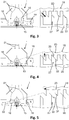
- a spray arm 1 is exemplary in FIG. 1 shown.
- the spray arm 1 has a distribution chamber 14. This distribution chamber 14 is connected to a supply line for rinsing liquor. In the proper charging case of the spray arm 1 with rinsing fluid this passes through the associated supply line into the distribution chamber 14 of the spray arm. 1
- the spray arm 1 provides two wings 2 and 3, each extending from the distribution chamber 14 opposite each other. Each of the two wings 2 and 3 is divided and has two channels, wherein the wing 2 via the channels 12 and 13 and the wing 3 via the channels 10 and 11 has.
- Each of the channels 10, 11, 12 and 13 is fluidly connected to a respective end of the associated wing 2 and 3 formed drive nozzle 4 and 5 respectively.
- the channels 10 and 13 each with a drive nozzle 5 and the channels 11 and 12 each with a drive nozzle 4 in fluid communication.
- the channels 10 to 13 are also connected to spray nozzles 8, is discharged through the intended use case rinse liquor in the direction of to be cleaned items.
- the drive nozzles 4 and 5 are used in the case of loading a rotary drive of the spray arm 1 about its axis of rotation 17 either in the left direction according to arrow 36, d. H. counterclockwise or in the opposite direction, d. H. in the right direction as indicated by arrow 37 in a clockwise direction.
- a rotational movement of the spray arm 1 in the left direction is achieved in that the drive nozzles 4 are charged in the direction of arrow 6 with rinsing, while the fluidically connected to the drive nozzles 5 channels 10 and 13 are kept closed for rinsing.
- the drive nozzles 5 fluidically connected to the channels 10 and 13 are to be unlocked, with simultaneous closing circuit of the channels 11 and 12, which are fluidically connected to the drive nozzles 4.
- distributing device 15 serves the structure and operation of the distributor 15 results in particular from the FIGS. 2 to 5 ,
- the distribution device 15 is designed to be rotatable about the axis of rotation 17 relative to the distribution chamber 14. It has a plate-shaped base body 18, the feed side a baffle section 19 for intended use in the direction of arrow 21 in the distribution chamber 14 inflowing rinse.
- the distributor 15 also has closure means 16, which are formed in the embodiment shown as a circular segment-shaped plate sections, which are distributed evenly around the axis of rotation 17 around supported by the base body 18, as can be seen in particular from the illustration FIGS. 1 . 6 and 7 results.
- the orientation of the closure means 16 is selected so that, with simultaneous opening, ie release of the channels 10 and 13, the two other channels 11 and 12 are closed are. In an opening or release of the channels 11 and 12, however, the other two channels 10 and 13 are closed.
- This factual context results from a synopsis of the FIGS. 6 and 7 , It puts FIG. 6 corresponding to the arrow 30 the clockwise and FIG. 7 in correspondence of the arrow 31, the left rotation of the spray arm 1.
- the distribution device 15 having the closure means 16 is to be rotated about the rotation axis 17. In this case, a rotational movement takes place automatically with the beginning of each new loading of the spray arm 1 with rinsing liquor.
- the distributor 15 has a slide track 23. This provides pin-shaped projections 24 which are equipped with an oblique surface 32 at the ends.
- the bottom 26 of the distribution chamber 14 is also equipped with a slide track 27.
- This has webs 28, the Verteil originateds person have an inclined surface 33.
- the slide tracks 23 and 27 and their respective projections 24 and 28 respectively supported oblique surfaces 32 and 33 act together in the intended use case.
- the closure means 16 of the distributor 15 have a reference to the plane of the drawing FIG. 2 upper end edge 34.
- This upper end edge 34 is formed by a provided from the wall of the distribution chamber 14 annular edge 35 opposite.
- the end edge 34 and the annular edge 35 carry a correspondingly formed to each other toothing or comparable contour.
- the distributor 15 is arranged with the interposition of a compression spring 20 within the distribution chamber 14.
- the deflected normal position of the distributor 15 is in FIG. 2 shown. In this normal position, the slide tracks 23 and 27 are disengaged.
- FIG. 3 lets the distributor 15 recognize in a spring-loaded normal position.
- the distributor 15 is in such a relative position to the distribution chamber 14 that the channels 12 and 11 are closed by the corresponding closure means 16.
- the two other channels 10 and 13 are meanwhile open.
- the distributor device 15 returns to the normal position, ie with reference to the plane of the drawing, according to the spring force caused by the spring 20 FIGS. 2 to 5 back up.
- the toothing provided by the closing edges 34 of the closure means 16 engages in the toothing provided by the opposing annular edge 35, as a result of which a subsequent rotational movement of the distributor 15 occurs relative to the distribution chamber 14, namely by such an angle that the Sloping surfaces 32 and 33 are at least partially brought into coincidence, so that when a renewed introduction of wash liquor in the spray arm 1 at a lowering of the distributor 15 an operative connection between the two inclined surfaces 32 and 33 can come about, as described above with reference to FIG.
- the geometric dimensions of the slide tracks 23 and 27 are chosen so that the distance 9 between the center line of an extension 24 and the center line of a release 25 is dimensioned such that in the course of a proper loading of the spray arm with rinsing a twisting motion the distributor 15 is achieved by preferably 45 °.
Description
Die Erfindung betrifft eine Geschirrspülmaschine mit einem Spülraum und einem im Spülraum vorgesehenen Sprühsystem, das einen drehbar gelagerten Sprüharm aufweist, wobei der Sprüharm Antriebsdüsen aufweist, welche Antriebsdüsen einem Drehantrieb des Sprüharms in Linksrichtung einerseits sowie in Rechtsrichtung andererseits dienen.The invention relates to a dishwasher having a washing compartment and a spray system provided in the washing compartment, which has a rotatably mounted spray arm, wherein the spray arm drive nozzles, which drive nozzles serve a rotary drive of the spray arm in the left direction on the one hand and in the right direction on the other.
Geschirrspülmaschinen der eingangs genannten Art sind aus dem Stand der Technik an sich bekannt. Eines gesonderten druckschriftlichen Nachweises bedarf es an dieser Stelle deshalb nicht.Dishwashers of the type mentioned are known from the prior art per se. A separate documentary proof is therefore not required at this point.
Gattungsgemäße Geschirrspülmaschinen verfügen über einen Spülbottich, der seinerseits einen Spülraum bereitstellt. Der Spülraum ist über eine Öffnung im Spülbottich zugänglich, welche Öffnung mittels einer verschwenkbar am Spülbottich angeordneten Tür fluiddicht verschließbar ist.Generic dishwashers have a Spülbottich, which in turn provides a Spülraum. The washing compartment is accessible via an opening in the washing tub, which opening can be closed in a fluid-tight manner by means of a door pivotably arranged on the washing tub.
Im bestimmungsgemäßen Verwendungsfall dient der Spülraum der Geschirrspülmaschine der Aufnahme von zu reinigendem Spülgut. Dieses wird im Rahmen eines bestimmungsgemäßen Spülprogrammablaufs mittels Spülflüssigkeit, der sogenannten Spülflotte beaufschlagt.When used as intended, the washing compartment of the dishwasher serves to receive items to be cleaned. This is applied as part of a designated Spülprogrammablaufs by means of rinsing liquid, the so-called wash liquor.
Zur Beaufschlagung von zu reinigendem Spülgut mit Spülflotte verfügt eine Geschirrspülmaschine über ein im Spülraum vorgesehenes Sprühsystem. Ein solches System verfügt typischerweise über wenigstens einen drehbar gelagerten Sprüharm. In der Regel sind mehrere solcher Sprüharme vorgesehen, wobei je nach Ausgestaltung der Geschirrspülmaschine zwei oder drei Sprüharme gängige Praxis sind.A dishwashing machine has a spray system provided in the washing compartment for loading items to be cleaned with washing liquor. Such a system typically has at least one rotatably mounted spray arm. In general, several such spray arms are provided, and depending on the design of the dishwasher two or three spray arms are common practice.
Ein jeder Sprüharm ist an eine Zuleitung für Spülflotte angeschlossen. Über diese Zuleitung gelangt im Betriebsfall Spülflotte zum Sprüharm, über welchen die Spülflotte in Richtung auf das zu reinigende Spülgut abgegeben wird. Die vom Sprüharm abgegebene Spülflotte sammelt sich im Spülraum und wird für eine erneute Besprühung des Spülguts in einem offenen Strömungskreislauf geführt. Zu diesem Zweck kommt eine Umwälzpumpe zum Einsatz, die die Spülflotte während einer bestimmungsgemäßen Programmdurchführung stetig umwälzt.Each spray arm is connected to a supply line for rinsing liquor. In this case, rinsing liquor passes through this supply line to the spray arm, via which the rinsing liquor is discharged in the direction of the items to be cleaned. The rinsing liquor emitted by the spray arm collects in the washing compartment and is guided in an open flow circuit for a renewed spraying of the dishes. For this purpose, a circulation pump is used, which continuously circulates the rinsing liquor during a proper program implementation.
Typischerweise kommen bei einer Geschirrspülmaschine der eingangs genannten Art nicht alle Sprüharme gleichzeitig bei einem bestimmungsgemäßen Programmablauf zum Einsatz. Es findet vielmehr zu unterschiedlichen Programmabschnitten eine Beschickung unterschiedlicher Sprüharme mit Spülflotte statt, wobei zum Zwecke der Wassereinsparung bevorzugterweise nicht mehr als zwei Sprüharme gleichzeitig mit Spülflotte bedient werden. Zur Beschickung unterschiedlicher Sprüharme mit Spülflotte kommt regelmäßig eine mit der Umwälzpumpe zusammenwirkende Wasserweiche zum Einsatz, wobei eine Beschickung der Sprüharme in Abhängigkeit der Stellung der Wasserweiche erfolgt.Typically, in a dishwasher of the type mentioned above, not all the spray arms are used at the same time in a designated program sequence. It is rather a feed to different sections of the program different spray arms with rinsing liquor instead, for the purpose of water saving preferably not more than two spray arms are operated simultaneously with rinsing water. For feeding different spray arms with rinsing fluid, a water switch cooperating with the circulation pump is regularly used, wherein a feeding of the spray arms takes place as a function of the position of the water distributor.
Zum Zwecke eines Drehantriebes des Sprüharms verfügt dieser über Antriebsdüsen. Die
Die
Die
Die
Es ist ausgehend vom Vorbeschriebenen die Aufgabe der Erfindung, eine Geschirrspülmaschine der eingangs genannten Art dahingehend weiterzuentwickeln, dass eine verbesserte Abdeckung des Spülraums mit Spülflotte mit dem Ziel einer verbesserten Spülgutreinigung bei gleichzeitig vereinfachtem, preiswertem und robustem Aufbau erreicht ist.It is based on the above, the object of the invention to further develop a dishwasher of the type mentioned in that an improved coverage of the washing compartment with rinse liquor is achieved with the aim of improved Spülgutreinigung at the same time simplified, inexpensive and robust construction.
Zur Lösung dieser Aufgabe wird mit der Erfindung eine Geschirrspülmaschine mit den Merkmalen von Anspruch 1 vorgeschlagen.To solve this problem, the invention proposes a dishwasher with the features of
Die Geschirrspülmaschine nach der Erfindung verfügt über einen Sprüharm, der mit einer Verteilkammer und einer Verteileinrichtung für Spülflotte ausgerüstet ist. Die Verteilkammer ist somit innerhalb des Sprüharms angeordnet und wird über lediglich eine Zuführleitung mit Spülflüssigkeit beschickt. Die Verteileinrichtung ist verdrehbar innerhalb der Verteilkammer des Sprüharms angeordnet. Sie gibt je nach ihrer Stellung abwechselnd entweder die Antriebsdüsen für einen Drehantrieb des Sprüharms in Linksrichtung oder die Antriebsdüsen für einen Drehantrieb des Sprüharms in Rechtsrichtung frei. In vorteilhafter Weise kommt es so mit einer jeden Neubeschickung des Sprüharms mit Spülflotte zu einer Drehrichtungsumkehr. Hat also in einem vorangegangenen Programmabschnitt eine Verdrehbewegung des Sprüharms beispielsweise in Linksrichtung stattgefunden, so wird nach einer Beendigung dieses Programmabschnittes und anschließender Neubeschickung des Sprüharms mit Spülflotte eine Verdrehbewegung des Sprüharms in Rechtsrichtung durchgeführt werden. Die erfindungsgemäße Ausgestaltung erbringt mithin bei jeder Neubeschickung des Sprüharms mit Spülflotte einen sich umkehrenden, d. h. einen sich in seiner Drehrichtung abwechselnden Richtungssinn.The dishwasher according to the invention has a spray arm, which is equipped with a distribution chamber and a distributor for rinsing liquor. The distribution chamber is thus arranged within the spray arm and is supplied with rinsing liquid via only one supply line. The distributor is rotatably disposed within the distribution chamber of the spray arm. Depending on its position, it alternately releases either the drive nozzles for a rotary drive of the spray arm in the left direction or the drive nozzles for a rotary drive of the spray arm in the right direction. Advantageously, it comes with every new loading of the spray arm with rinsing water to a reversal of direction. Thus, if a twisting movement of the spray arm has taken place, for example, in the left-hand direction in a preceding program section, a twisting movement of the spray arm in the right-hand direction will be carried out after completion of this program section and subsequent recharge of the spray arm with wash liquor. The design according to the invention therefore yields a reversing upon each new loading of the spray arm with rinsing liquor, d. H. a sense of direction alternating in its direction of rotation.
Aufgrund der alternierenden Drehrichtung ergeben sich hinsichtlich des vom Spülraum der Spülmaschine aufgenommenen Spülgutes von Drehrichtungsumkehr zu Drehrichtungsumkehr unterschiedliche Spülflottenstrahlrichtungen, Auftreffwinkel und/oder Spülflottenstrahlformen. Aufgrund dessen stellt sich eine optimierte Abdeckung des Spülraums durch unterschiedliche Sprühbilder ein, was im Ergebnis in vorteilhafter Weise zu einem verbesserten Reinigungsresultat führt.Due to the alternating direction of rotation, different wash liquor jet directions, incidence angles and / or wash liquor jet shapes result with regard to the items to be washed picked up by the dishwasher's dishwasher compartment from the reversal of the direction of rotation to the reversal of the direction of rotation. Due to this, an optimized coverage of the washing compartment sets by different spray patterns, which results in an advantageous manner to an improved cleaning result.
Bei Spülmaschinen der eingangs genannten Art kommen typischerweise eine Mehrzahl von Sprüharmen zum Einsatz, die jeweils in einer Sprühebene wirken. Dabei können sich die Anforderungen an die Sprühstrahlcharakteristik eines Sprüharmes während eines Programmablaufes ändern. Gleiches gilt für die Realisierung unterschiedlicher Spülprogramme bzw. Spülphasen, wie z. B. Feinprogramm, Topfreinigungsprogramm, Siebreinigungsprogramm und dergleichen. Aus diesem Grunde stellt die Sprühstrahlcharakteristik der Sprüharme vorbekannter Geschirrspülmaschinen einen Kompromiss dar, der möglichst allen Anforderungen gerecht wird.In dishwashers of the type mentioned initially typically a plurality of spray arms are used, each acting in a spray level. The requirements for the spray jet characteristic of a spray arm can change during a program run. The same applies to the realization of different washing programs or rinsing phases, such. B. Fine program, pot cleaning program, sieve cleaning program and the like. For this reason, the spray jet characteristic the spray arms of prior art dishwashers is a compromise that meets all requirements as possible.
Die erfindungsgemäße Ausgestaltung schafft hier eine Verbesserung, da sie im Ergebnis durch eine Drehrichtungsumkehr des Sprüharms mit Bezug auf das zu reinigende Spülgut eine Strahlrichtungsveränderung, eine Strahlformveränderung sowie eine Veränderung im Strahlauftreffwinkel bewirkt, so dass unterschiedliche Sprühstrahlcharakteristiken erreicht sind. Damit kann im Ergebnis ein besseres Reinigungsresultat erreicht werden.The embodiment of the invention provides an improvement here, as a result of reversing the direction of rotation of the spray arm with respect to the items to be cleaned causes a beam direction change, a beam shape change and a change in Strahlauftreffwinkel so that different spray jet characteristics are achieved. As a result, a better cleaning result can be achieved.
Die Verteileinrichtung nach der Erfindung verfügt gemäß einem weiteren Merkmal der Erfindung über einen Grundkörper. Dieser trägt Verschlussmittel, mittels welcher je nach relativer Verdrehstellung der Verteileinrichtung innerhalb der Verteilkammer eine Freigabe der Antriebsdüsen ausgebildet ist, wobei entweder die Antriebsdüsen für einen Drehantrieb des Sprüharms in Linksrichtung oder die Antriebsdüsen für einen Drehantrieb des Sprüharms in Rechtsrichtung freigegeben sind.The distribution device according to the invention according to a further feature of the invention has a base body. This carries closure means, by means of which depending on the relative rotational position of the distributor within the distribution chamber release of the drive nozzles is formed, either the drive nozzles for a rotary drive of the spray arm in the left direction or the drive nozzles are released for a rotary drive of the spray arm in the right direction.
Ein Sprüharm verfügt bevorzugterweise über zwei Flügel, die jeweils ausgehend von der Verteilkammer des Sprüharms ausgebildet sind. Dabei verfügt jeder Flügel über zwei Kanäle und jeder dieser Kanäle ist jeweils an zumindest eine Antriebsdüse angeschlossen.A spray arm preferably has two wings which are each formed starting from the distribution chamber of the spray arm. Each wing has two channels and each of these channels is connected to at least one drive nozzle.
Mittels der vom Grundkörper der Verteileinrichtung bereitgestellten Verschlussmittel können die mit den Antriebsdüsen strömungstechnisch verbundenen Kanäle des Sprüharms verschlossen werden. Im einfachsten Ausführungsfall sind die Verschlussmittel plattenförmig ausgebildet und korrespondierend zu den Kanaleintrittsöffnungen ausgebildet. Ist im bestimmungsgemäßen Anwendungsfall eine Kanaleintrittsöffnung mittels eines plattenförmigen Verschlussmittels verschlossen ausgebildet, so kann in diesen Kanal keine Spülflotte einströmen, womit die diesem Kanal zugehörige Antriebsdüse nicht mit Spülflotte beschickt wird.By means of the closure means provided by the base body of the distributor, the channels of the spray arm fluidly connected to the drive nozzles can be closed. In the simplest embodiment, the closure means are plate-shaped and formed corresponding to the channel inlet openings. If, in the intended application, a channel inlet opening is closed by means of a plate-shaped closure means, then no rinse liquor can flow into this channel, with which the drive nozzle belonging to this channel is not charged with rinsing liquor.
Die Verteileinrichtung ist gemäß einem weiteren Merkmal der Erfindung unter Zwischenordnung einer Druckfeder innerhalb der Verteilkammer angeordnet. Sie ist aufgrund dieser Feder in Richtung ihrer Drehachse unter Federvorspannung gehalten. Dabei wirkt die Feder entgegen der Einströmrichtung einer in den Sprüharm einströmenden Spülflotte. Die Feder ist hinsichtlich ihrer Federkraft so bemessen, dass die Verteileinrichtung bei in den Sprüharm einströmender Spülflotte entgegen der Federkraft niedergedrückt wird. Bei mangelnder Spülflottenbeschickung wird die Verteileinrichtung hingegen der Federwirkung der Druckfeder folgend in ihrer ausgefahrenen Normalstellung gehalten.The distribution device is arranged according to a further feature of the invention with the interposition of a compression spring within the distribution chamber. It is held under spring bias in the direction of its axis of rotation due to this spring. In this case, the spring counteracts the direction of inflow of a washing liquor flowing into the spray arm. The spring is dimensioned with regard to its spring force so that the distributor is depressed against the spring force when flushing water flowing into the spray arm. In the case of a lack of rinsing liquor feed, the distribution device, on the other hand, is held in its extended normal position following the spring action of the compression spring.
Die Verteileinrichtung und die Verteilkammer verfügen gemäß einem weiteren Merkmal der Erfindung jeweils über eine Kulissenbahn, wobei die beiden Kulissenbahnen in Wirkverbindung miteinander stehen. Die Wirkverbindung ist derart gestaltet, dass eine stufenweise Verdrehung der Verteileinrichtung relativ gegenüber der Verteilkammer bewirkbar ist. Über die Kulissenbahnen wird eine automatische Verdrehbewegung der Verteileinrichtung zum Zwecke der Drehrichtungsumkehr erreicht. Die Verdrehbewegung erfolgt automatisch bei einer Relativbewegung von Verteileinrichtung und Verteilkammer, insbesondere wenn diese sich aufeinander zu bewegen.The distribution device and the distribution chamber have according to a further feature of the invention each have a slide track, wherein the two slide tracks are in operative connection with each other. The operative connection is designed such that a stepwise rotation of the distributor relative to the distribution chamber is effected. About the slide tracks an automatic rotational movement of the distributor is achieved for the purpose of reversing the direction of rotation. The twisting movement takes place automatically during a relative movement of distributor and distribution chamber, in particular if they move toward each other.
Die Kulissenbahnen verfügen zu diesem Zweck über einander zugewandte Schrägflächen, über die im Wirkungseingriffsfall eine Verdrehbewegung der Verteileinrichtung relativ gegenüber der Verteilkammer und damit auch relativ gegenüber dem Sprüharm erreicht ist.For this purpose, the slide tracks have mutually facing inclined surfaces over which, in the case of engagement, a rotational movement of the distributor is achieved relative to the distributor chamber and thus also relative to the spray arm.
Dabei bewirken die Kulissenbahnen eine stufenweise Verdrehung der Verteileinrichtung relativ gegenüber der Verteilkammer, und zwar bevorzugterweise um 45°.In this case, the slide tracks cause a gradual rotation of the distributor relative to the distribution chamber, and preferably by 45 °.
Der Grundkörper der Verteileinrichtung verfügt beschickungsseitig über einen Prallabschnitt. Auf diesen Prallabschnitt trifft bei einer Beschickung des Sprüharms mit Spülflotte die in den Sprüharm eintretende Spülflotte auf. Es erfolgt eine zu allen Seiten bevorzugterweise gleichmäßiger Abführung der Spülflotte, so dass eine gleichmäßige Beaufschlagung der freigegebenen Kanäle des Sprüharms mit Spülflotte erfolgen kann.The main body of the distributor has the feed side over a baffle section. Upon impingement of the spray arm with rinse liquor, the rinse liquor entering the spray arm encounters this baffle section. There is an on all sides preferably uniform discharge of the rinsing liquor, so that a uniform loading of the shared channels of the spray arm can be done with rinsing liquor.
Mit der Erfindung wird insgesamt eine Konstruktion vorgeschlagen, mit der gemäß hinsichtlich eines Sprüharms eine Drehrichtungsumkehr erreicht ist. Dabei kann ein jeder Sprüharm der Geschirrspülmaschine in erfindungsgemäßer Weise ausgebildet sein. Die Konstruktion nach der Erfindung bewirkt bei jeder Neubeschickung des Sprüharms mit Spülflotte eine Änderung der Drehrichtung. Dies wird durch eine von der Verteilkammer des Sprüharms aufgenommene Verteileinrichtung erreicht, die mit einer jeden Neubeschickung des Sprüharms mit Spülflotte um einen vorgegebenen Verdrehwinkel, vorzugsweise 45° weiterdreht, womit jeweils eine Freischaltung der vom Sprüharm bereitgestellten Antriebsdüsen entweder für eine Linksdrehung des Sprüharms oder eine Rechtsdrehung des Sprüharms erfolgt.With the invention, a construction is proposed as a whole, with respect to a direction of rotation is achieved with respect to a Sprüharms. In this case, each spray arm of the dishwasher can be designed in accordance with the invention. The construction according to the invention causes a change in the direction of rotation with each new loading of the spray arm with rinsing. This is achieved by a recorded from the distribution chamber of the spray arm distribution device, which rotates with each new loading of the spray arm with rinsing fluid by a predetermined angle of rotation, preferably 45 °, which in each case an activation of the spray provided by the spray drive either for a left-hand rotation of the spray arm or a clockwise rotation the spray arm takes place.
Durch die Erfindung ist eine besonders einfache und preiswerte Möglichkeit offenbart, eine automatische Drehrichtungsumkehr des Sprüharms zu erreichen. Die Drehrichtungsumkehr wird dabei unmittelbar durch den Druck der Spülflotte bewirkt und ist dadurch mit geringem Aufwand und ohne weitere störanfällige Hilfsmittel auf einfache Weise durch die Steuerung des Spülflottenstroms einstellbar.The invention discloses a particularly simple and inexpensive way to achieve an automatic reversal of the direction of the spray arm. The direction of rotation reversal is effected directly by the pressure of the rinsing liquor and is thus adjustable with little effort and without further interference-prone aids in a simple manner by controlling the Spülflottenstroms.
Weitere Vorteile und Merkmale der Erfindung ergeben sich aus der nachfolgenden Beschreibung anhand der Figuren. Dabei zeigen:
Figur 1- in schematischer Draufsicht von oben einen Sprüharm nach der Erfindung;
Figur 2- in einer schematischen Seitenansicht sowie in einer Ausschnittsdarstellung die Verteileinrichtung nach der Erfindung;
Figur 3- in einer schematischen Seitenansicht sowie in einer Ausschnittsdarstellung die Verteileinrichtung in einer ersten Stellung;
Figur 4- in einer schematischen Seitenansicht sowie in einer Ausschnittsdarstellung die Verteileinrichtung in einer zweiten Stellung;
Figur 5- in einer schematischen Seitenansicht sowie in einer Ausschnittsdarstellung die Verteileinrichtung in einer dritten Stellung;
Figur 6- in einer schematischen Draufsicht von oben die Verteilkammer des erfindungsgemäßen Sprüharms mit einer Verteileinrichtung in einer ersten Stellung und
Figur 7- in einer schematischen Draufsicht von oben die Verteilkammer des erfindungsgemäßen Sprüharms mit einer Verteileinrichtung in einer zweiten Stellung.
- FIG. 1
- a schematic top view of a spray arm according to the invention;
- FIG. 2
- in a schematic side view and in a sectional view of the distribution device according to the invention;
- FIG. 3
- in a schematic side view and in a sectional view of the distribution device in a first position;
- FIG. 4
- in a schematic side view and in a sectional view of the distribution device in a second position;
- FIG. 5
- in a schematic side view and in a sectional view of the distributor in a third position;
- FIG. 6
- in a schematic plan view from above the distribution chamber of the spray arm according to the invention with a distributor in a first position and
- FIG. 7
- in a schematic plan view from above the distribution chamber of the spray arm according to the invention with a distributor in a second position.
Eine in den Figuren nicht näher dargestellte Geschirrspülmaschine nach der Erfindung verfügt über einen Spülraum und ein im Spülraum vorgesehenes Sprühsystem. Dabei dient das Sprühsystem der Beschickung von zu reinigendem Spülgut mit Spülflüssigkeit, auch Spülflotte genannt.A dishwashing machine according to the invention not shown in the figures has a washing compartment and a spraying system provided in the washing compartment. In this case, the spray system is used for the loading of items to be cleaned with rinsing liquid, also called rinsing liquor.
Zur Beschickung von zu reinigendem Spülgut mit Spülflotte verfügt das Sprühsystem über vorzugsweise in einzelnen Lagen übereinander angeordnete Sprüharme, die drehbar gelagert sind. Ein solcher Sprüharm 1 ist exemplarisch in
Der Sprüharm 1 verfügt über eine Verteilkammer 14. Diese Verteilkammer 14 ist an eine Zuführungsleitung für Spülflotte angeschlossen. Im bestimmungsgemäßen Beschickungsfall des Sprüharms 1 mit Spülflotte gelangt diese über die zugehörige Zuführungsleitung in die Verteilkammer 14 des Sprüharms 1.The
Der Sprüharm 1 stellt zwei Flügel 2 und 3 bereit, die sich jeweils ausgehend von der Verteilkammer 14 einander gegenüberliegend erstrecken. Jeder der beiden Flügel 2 und 3 ist unterteilt ausgebildet und verfügt über zwei Kanäle, wobei der Flügel 2 über die Kanäle 12 und 13 und der Flügel 3 über die Kanäle 10 und 11 verfügt.The
Ein jeder der Kanäle 10, 11, 12 und 13 ist an eine jeweils endseitig des zugehörigen Flügels 2 bzw. 3 ausgebildete Antriebsdüse 4 bzw. 5 strömungstechnisch angeschlossen. Dabei stehen die Kanäle 10 und 13 jeweils mit einer Antriebsdüse 5 und die Kanäle 11 und 12 jeweils mit einer Antriebsdüse 4 in strömungstechnischer Verbindung. Die Kanäle 10 bis 13 sind ferner an Sprühdüsen 8 angeschlossen, über die im bestimmungsgemäßen Verwendungsfall Spülflotte in Richtung auf zu reinigendes Spülgut abgegeben wird.Each of the
Die Antriebsdüsen 4 und 5 dienen im Beschickungsfall einem Drehantrieb des Sprüharms 1 um seine Drehachse 17 entweder in Linksrichtung gemäß Pfeil 36, d. h. entgegen des Uhrzeigersinns oder in entgegengesetzter Richtung, d. h. in Rechtsrichtung gemäß Pfeil 37 im Uhrzeigersinn. Dabei wird eine Verdrehbewegung des Sprüharms 1 in Linksrichtung dadurch erreicht, dass die Antriebsdüsen 4 in Richtung des Pfeils 6 mit Spülflotte beschickt werden, während die mit den Antriebsdüsen 5 strömungstechnisch verbundenen Kanäle 10 und 13 für Spülflotte geschlossen halten werden. Für eine Verdrehbewegung des Sprüharms in umgekehrter Richtung, d. h. in Rechtsrichtung sind die mit den Kanälen 10 und 13 strömungstechnisch verbundenen Antriebsdüsen 5 freizuschalten, und zwar bei gleichzeitiger Verschlussschaltung der Kanäle 11 und 12, die mit den Antriebsdüsen 4 strömungstechnisch verbunden sind.The
Zur Beschickung entweder der Kanäle 10 und 13 oder der Kanäle 11 und 12 mit Spülflotte dient eine von der Verteilkammer 14 aufgenommene Verteileinrichtung 15. Der Aufbau und die Funktionsweise der Verteileinrichtung 15 ergibt sich insbesondere aus den
Die Verteileinrichtung 15 ist um die Drehachse 17 relativ zur Verteilkammer 14 verdrehbar ausgebildet. Sie verfügt über einen plattenförmig ausgebildeten Grundkörper 18, der beschickungsseitig einen Prallabschnitt 19 für im bestimmungsgemäßen Verwendungsfall in Pfeilrichtung 21 in die Verteilkammer 14 einströmende Spülflotte.The
Die Verteileinrichtung 15 verfügt darüber hinaus über Verschlussmittel 16, die im gezeigten Ausführungsbeispiel als kreissegmentförmige Plattenabschnitte ausgebildet sind, die gleich verteilt um die Drehachse 17 herum angeordnet von dem Grundkörper 18 getragen sind, wie sich insbesondere aus der Darstellung nach den
Die Ausrichtung der Verschlussmittel 16 ist so gewählt, dass bei gleichzeitiger Öffnung, d. h. Freigabe der Kanäle 10 und 13 die beiden anderen Kanäle 11 und 12 geschlossen sind. Bei einer Öffnung bzw. Freigabe der Kanäle 11 und 12 sind indes die beiden anderen Kanäle 10 und 13 geschlossen. Dieser Sachzusammenhang ergibt sich aus einer Zusammenschau der
Zur Umschaltung vom Rechtslauf nach
Die Verteileinrichtung 15 verfügt über eine Kulissenbahn 23. Diese stellt stiftförmige Fortsätze 24 bereit, die endseitig mit einer Schrägfläche 32 ausgerüstet sind.The
Der Boden 26 der Verteilkammer 14 ist ebenfalls mit einer Kulissenbahn 27 ausgerüstet. Diese verfügt über Stege 28, die verteileinrichtungsseitig über eine Schrägfläche 33 verfügen. Die Kulissenbahnen 23 und 27 bzw. ihre von den Fortsätzen 24 und 28 jeweils getragenen Schrägflächen 32 und 33 wirken im bestimmungsgemäßen Verwendungsfall zusammen.The bottom 26 of the
Zwischen den Fortsätzen 24 der Kulissenbahn 23 sind Freilassungen 25 vorgesehen. Zwischen den Stegen 28 der Kulissenbahn 27 ist jeweils ein Freiraum 29 ausgebildet, wobei ein Freiraum 29 in Breitenrichtung den Abmessungen von zwei Freilassungen 25 und eines Fortsatzes 24 entspricht, wie sich insbesondere aus der Darstellung nach
Die Verschlussmittel 16 der Verteileinrichtung 15 verfügen über eine mit Bezug auf die Zeichnungsebene nach
Die Verteileinrichtung 15 ist unter Zwischenordnung einer Druckfeder 20 innerhalb der Verteilkammer 14 angeordnet. Die ausgelenkte Normalstellung der Verteileinrichtung 15 ist in
Die Funktionsweise der erfindungsgemäßen Ausgestaltung ergibt sich insbesondere aus einer Zusammenschau der
Im Beschickungsfall strömt Spülflott in Entsprechung des Pfeils 21 in die Verteilkammer 14 ein. Infolge dieses Einströmens wird die Verteileinrichtung 15 durch die Spülflotte mit Bezug auf die Zeichnungsebene nach
Sobald die Beschickung des Sprüharms 1 mit Spülflotte stoppt, fährt die Verteileinrichtung 15 in Entsprechung der durch die Feder 20 bewirkten Federkraft wieder in die Normalstellung, d. h. mit Bezug auf die Zeichnungsebene nach den
- 11
- Sprüharmspray arm
- 22
- Flügelwing
- 33
- Flügelwing
- 44
- Antriebsdüsedrive nozzle
- 55
- Antriebsdüsedrive nozzle
- 66
- Pfeilarrow
- 77
- Pfeilarrow
- 88th
- Sprühdüsespray nozzle
- 99
- Abstanddistance
- 1010
- Kanalchannel
- 1111
- Kanalchannel
- 1212
- Kanalchannel
- 1313
- Kanalchannel
- 1414
- Verteilkammerdistribution chamber
- 1515
- Verteileinrichtungdistributor
- 1616
- Verschlussmittelclosure means
- 1717
- Drehachseaxis of rotation
- 1818
- Grundkörperbody
- 1919
- Prallabschnittbaffle section
- 2020
- Federfeather
- 2121
- Pfeilarrow
- 2222
- Pfeilarrow
- 2323
- Kulissenbahnlink path
- 2424
- Fortsatzextension
- 2525
- Freilassungrelease
- 2626
- Bodenground
- 2727
- Kulissenbahnlink path
- 2828
- Stegweb
- 2929
- Freiraumfree space
- 3030
- Pfeilarrow
- 3131
- Pfeilarrow
- 3232
- Schrägflächesloping surface
- 3333
- Schrägflächesloping surface
- 3434
- Abschlusskanteterminal edge
- 3535
- Ringkanteannular edge
- 3636
- Pfeilarrow
- 3737
- Pfeilarrow
Claims (8)
- Dishwasher comprising a washing chamber and a spray system which is provided in the washing chamber and has a rotatably mounted spray arm (1), the spray arm (1) comprising drive nozzles (4, 5), which drive nozzles (4, 5) are for rotationally driving the spray arm (1) in both the left direction and the right direction,
the spray arm (1) comprising a distribution chamber (14), to which the drive nozzles (4, 5) are fluidically connected, and a distribution device (15), which is arranged so as to be rotatable inside the distribution chamber (14), which distribution device alternately either opens the drive nozzles (4) for rotationally driving the spray arm in the left direction or opens the drive nozzles (5) for rotationally driving the spray arm in the right direction,
characterised in that
the distribution device (15) is arranged inside the distribution chamber (14), with the interposition of a compression spring (20), and is spring-preloaded towards the axis of rotation (17) of said distribution device, the distribution device (15) being pressed down against the force of the spring when washing solution flows into the spray arm (1),
and in that the distribution device (15) and the distribution chamber (14) each have a slider track (23, 27), which two slider tracks (23, 27) are operatively interconnected in such a way that, when the distribution device and the distribution chamber move relative to one another, step-by-step rotation of the distribution device (15) relative to the distribution chamber (14) can be brought about. - Dishwasher according to claim 1,
characterised in that
the distribution device (15) comprises a base body (18) that carries closure means (16) by means of which, depending on the relative rotational position of the distribution device (15) inside the distribution chamber (14), the drive nozzles (4) are opened for rotationally driving the spray arm in the left direction or the drive nozzles (5) are opened for rotationally driving the spray arm (1) in the right direction. - Dishwasher according to either of the preceding claims,
characterised in that
the slider tracks (23, 27) have oblique faces (32, 33) that face one another. - Dishwasher according to any of the preceding claims,
characterised in that
the slider tracks (23, 27) cause step-by-step rotation, by 45°, of the distribution device (15) relative to the distribution chamber (14). - Dishwasher according to any of the preceding claims 2 to 4,
characterised in that
the base body (18) of the distribution device (15) comprises a deflector portion (19) on the loading side. - Dishwasher according to any of the preceding claims,
characterised in that
the spray arm (1) comprises two blades (2, 3), each of which extends out from the distribution chamber (14). - Dishwasher according to claim 6,
characterised in that
each blade (2, 3) comprises two channels (10, 11; 12, 13), each channel (10, 11, 12, 13) being connected to a drive nozzle (4, 5). - Dishwasher according to claim 7,
characterised in that
each channel (10, 11, 12, 13) is connected to a plurality of spray nozzles (8).
Applications Claiming Priority (1)
| Application Number | Priority Date | Filing Date | Title |
|---|---|---|---|
| DE102011056065A DE102011056065A1 (en) | 2011-12-06 | 2011-12-06 | dishwasher |
Publications (3)
| Publication Number | Publication Date |
|---|---|
| EP2601877A2 EP2601877A2 (en) | 2013-06-12 |
| EP2601877A3 EP2601877A3 (en) | 2016-03-02 |
| EP2601877B1 true EP2601877B1 (en) | 2018-02-21 |
Family
ID=47504755
Family Applications (1)
| Application Number | Title | Priority Date | Filing Date |
|---|---|---|---|
| EP12401244.4A Active EP2601877B1 (en) | 2011-12-06 | 2012-12-06 | Dishwasher with automatic reversal of the direction of rotation of the spray arm |
Country Status (2)
| Country | Link |
|---|---|
| EP (1) | EP2601877B1 (en) |
| DE (1) | DE102011056065A1 (en) |
Families Citing this family (6)
| Publication number | Priority date | Publication date | Assignee | Title |
|---|---|---|---|---|
| CN106606341B (en) * | 2015-10-21 | 2020-04-28 | 青岛海尔洗碗机有限公司 | Spray header and sprayer |
| KR101943323B1 (en) * | 2017-01-02 | 2019-01-29 | 엘지전자 주식회사 | Dish washer |
| DE102017207990B4 (en) * | 2017-05-11 | 2020-07-30 | Haier Deutschland GmbH | Switchable liquid dispenser with spring element |
| TR201716895A2 (en) * | 2017-10-31 | 2019-05-21 | Arcelik As | ONE WASHING BLADE |
| CN109259693A (en) * | 2018-11-14 | 2019-01-25 | 佛山市顺德区美的洗涤电器制造有限公司 | Gushing arm component and dish-washing machine for dish-washing machine |
| CN112617707A (en) * | 2019-10-08 | 2021-04-09 | 青岛海尔洗碗机有限公司 | Spraying structure and dish washing machine |
Family Cites Families (4)
| Publication number | Priority date | Publication date | Assignee | Title |
|---|---|---|---|---|
| DE7024995U (en) * | 1971-03-11 | Robert Bosch Gmbh | Dishwasher | |
| US3160164A (en) * | 1963-10-03 | 1964-12-08 | Tappan Co | Washer with reversing spray assembly |
| DE3816408A1 (en) | 1988-05-13 | 1989-11-16 | Licentia Gmbh | Dishwashing machine with a changeover device |
| DE10355343B3 (en) | 2003-11-25 | 2005-04-07 | Miele & Cie. Kg | Electric dishwashing machine with circulation pump and rotary spray arm with pseudo-random selection of different spray jet groups |
-
2011
- 2011-12-06 DE DE102011056065A patent/DE102011056065A1/en not_active Withdrawn
-
2012
- 2012-12-06 EP EP12401244.4A patent/EP2601877B1/en active Active
Non-Patent Citations (1)
| Title |
|---|
| None * |
Also Published As
| Publication number | Publication date |
|---|---|
| EP2601877A3 (en) | 2016-03-02 |
| EP2601877A2 (en) | 2013-06-12 |
| DE102011056065A1 (en) | 2013-06-06 |
Similar Documents
| Publication | Publication Date | Title |
|---|---|---|
| EP2601877B1 (en) | Dishwasher with automatic reversal of the direction of rotation of the spray arm | |
| DE60028277T2 (en) | Dishwasher with spray arms | |
| EP2214546B1 (en) | Water-carrying domestic appliance having a water-distribution mechanism | |
| EP2404539B1 (en) | Water distributor for a water conducting domestic appliance | |
| DE60013345T2 (en) | Dishwasher with pulsating water jets | |
| EP1586264B1 (en) | Dishwasher with a tub and a least one sprayarm arranged within the tub | |
| EP2891446B1 (en) | Dishwasher | |
| DE102007057336A1 (en) | Water-conducting household appliance with a water diverter | |
| DE19832982A1 (en) | Dishwashing device for a dishwasher | |
| EP3085293B1 (en) | Spray arm assembly and dishwasher | |
| EP2601878B1 (en) | Dishwasher with automatic reversal of the direction of rotation of the spray arm | |
| EP3833490B1 (en) | Surface-cleaning head | |
| DE7024995U (en) | Dishwasher | |
| EP1334687B2 (en) | Dishwasher | |
| DE19926962B4 (en) | Dishwasher with height-adjustable basket | |
| DE2622785C3 (en) | Dishwasher with a device for controlling the pressure of the washing water in the spray arms | |
| DE102017105589B4 (en) | Spraying device for a dishwasher | |
| EP2789285B1 (en) | Spray nozzle for a dishwasher | |
| DE69911556T2 (en) | Dishwasher with rotating nozzles for homogeneous water spraying | |
| EP3120747B1 (en) | Washing system for a dishwasher, and dishwasher with such a washing system | |
| EP3586713A1 (en) | Spray arm for a dishwasher | |
| DE102017112026A1 (en) | Spraying device and nozzle device for a household appliance, household appliance and method for operating a spraying device for a household appliance | |
| DE102021111959A1 (en) | Water distributor for a dishwasher | |
| DE6938271U (en) | DISHWASHER |
Legal Events
| Date | Code | Title | Description |
|---|---|---|---|
| PUAI | Public reference made under article 153(3) epc to a published international application that has entered the european phase |
Free format text: ORIGINAL CODE: 0009012 |
|
| AK | Designated contracting states |
Kind code of ref document: A2 Designated state(s): AL AT BE BG CH CY CZ DE DK EE ES FI FR GB GR HR HU IE IS IT LI LT LU LV MC MK MT NL NO PL PT RO RS SE SI SK SM TR |
|
| AX | Request for extension of the european patent |
Extension state: BA ME |
|
| PUAL | Search report despatched |
Free format text: ORIGINAL CODE: 0009013 |
|
| AK | Designated contracting states |
Kind code of ref document: A3 Designated state(s): AL AT BE BG CH CY CZ DE DK EE ES FI FR GB GR HR HU IE IS IT LI LT LU LV MC MK MT NL NO PL PT RO RS SE SI SK SM TR |
|
| AX | Request for extension of the european patent |
Extension state: BA ME |
|
| RIC1 | Information provided on ipc code assigned before grant |
Ipc: A47L 15/42 20060101ALI20160125BHEP Ipc: A47L 15/23 20060101AFI20160125BHEP |
|
| 17P | Request for examination filed |
Effective date: 20160902 |
|
| RBV | Designated contracting states (corrected) |
Designated state(s): AL AT BE BG CH CY CZ DE DK EE ES FI FR GB GR HR HU IE IS IT LI LT LU LV MC MK MT NL NO PL PT RO RS SE SI SK SM TR |
|
| 17Q | First examination report despatched |
Effective date: 20170517 |
|
| GRAP | Despatch of communication of intention to grant a patent |
Free format text: ORIGINAL CODE: EPIDOSNIGR1 |
|
| INTG | Intention to grant announced |
Effective date: 20171012 |
|
| GRAS | Grant fee paid |
Free format text: ORIGINAL CODE: EPIDOSNIGR3 |
|
| GRAA | (expected) grant |
Free format text: ORIGINAL CODE: 0009210 |
|
| AK | Designated contracting states |
Kind code of ref document: B1 Designated state(s): AL AT BE BG CH CY CZ DE DK EE ES FI FR GB GR HR HU IE IS IT LI LT LU LV MC MK MT NL NO PL PT RO RS SE SI SK SM TR |
|
| REG | Reference to a national code |
Ref country code: GB Ref legal event code: FG4D Free format text: NOT ENGLISH |
|
| REG | Reference to a national code |
Ref country code: CH Ref legal event code: EP |
|
| REG | Reference to a national code |
Ref country code: AT Ref legal event code: REF Ref document number: 970788 Country of ref document: AT Kind code of ref document: T Effective date: 20180315 |
|
| REG | Reference to a national code |
Ref country code: IE Ref legal event code: FG4D Free format text: LANGUAGE OF EP DOCUMENT: GERMAN |
|
| REG | Reference to a national code |
Ref country code: DE Ref legal event code: R096 Ref document number: 502012012186 Country of ref document: DE |
|
| REG | Reference to a national code |
Ref country code: GB Ref legal event code: 746 Effective date: 20180307 |
|
| REG | Reference to a national code |
Ref country code: DE Ref legal event code: R084 Ref document number: 502012012186 Country of ref document: DE |
|
| REG | Reference to a national code |
Ref country code: NL Ref legal event code: MP Effective date: 20180221 |
|
| REG | Reference to a national code |
Ref country code: LT Ref legal event code: MG4D |
|
| PG25 | Lapsed in a contracting state [announced via postgrant information from national office to epo] |
Ref country code: FI Free format text: LAPSE BECAUSE OF FAILURE TO SUBMIT A TRANSLATION OF THE DESCRIPTION OR TO PAY THE FEE WITHIN THE PRESCRIBED TIME-LIMIT Effective date: 20180221 Ref country code: NO Free format text: LAPSE BECAUSE OF FAILURE TO SUBMIT A TRANSLATION OF THE DESCRIPTION OR TO PAY THE FEE WITHIN THE PRESCRIBED TIME-LIMIT Effective date: 20180521 Ref country code: HR Free format text: LAPSE BECAUSE OF FAILURE TO SUBMIT A TRANSLATION OF THE DESCRIPTION OR TO PAY THE FEE WITHIN THE PRESCRIBED TIME-LIMIT Effective date: 20180221 Ref country code: ES Free format text: LAPSE BECAUSE OF FAILURE TO SUBMIT A TRANSLATION OF THE DESCRIPTION OR TO PAY THE FEE WITHIN THE PRESCRIBED TIME-LIMIT Effective date: 20180221 Ref country code: CY Free format text: LAPSE BECAUSE OF FAILURE TO SUBMIT A TRANSLATION OF THE DESCRIPTION OR TO PAY THE FEE WITHIN THE PRESCRIBED TIME-LIMIT Effective date: 20180221 Ref country code: LT Free format text: LAPSE BECAUSE OF FAILURE TO SUBMIT A TRANSLATION OF THE DESCRIPTION OR TO PAY THE FEE WITHIN THE PRESCRIBED TIME-LIMIT Effective date: 20180221 Ref country code: NL Free format text: LAPSE BECAUSE OF FAILURE TO SUBMIT A TRANSLATION OF THE DESCRIPTION OR TO PAY THE FEE WITHIN THE PRESCRIBED TIME-LIMIT Effective date: 20180221 |
|
| PG25 | Lapsed in a contracting state [announced via postgrant information from national office to epo] |
Ref country code: GR Free format text: LAPSE BECAUSE OF FAILURE TO SUBMIT A TRANSLATION OF THE DESCRIPTION OR TO PAY THE FEE WITHIN THE PRESCRIBED TIME-LIMIT Effective date: 20180522 Ref country code: BG Free format text: LAPSE BECAUSE OF FAILURE TO SUBMIT A TRANSLATION OF THE DESCRIPTION OR TO PAY THE FEE WITHIN THE PRESCRIBED TIME-LIMIT Effective date: 20180521 Ref country code: RS Free format text: LAPSE BECAUSE OF FAILURE TO SUBMIT A TRANSLATION OF THE DESCRIPTION OR TO PAY THE FEE WITHIN THE PRESCRIBED TIME-LIMIT Effective date: 20180221 Ref country code: LV Free format text: LAPSE BECAUSE OF FAILURE TO SUBMIT A TRANSLATION OF THE DESCRIPTION OR TO PAY THE FEE WITHIN THE PRESCRIBED TIME-LIMIT Effective date: 20180221 Ref country code: SE Free format text: LAPSE BECAUSE OF FAILURE TO SUBMIT A TRANSLATION OF THE DESCRIPTION OR TO PAY THE FEE WITHIN THE PRESCRIBED TIME-LIMIT Effective date: 20180221 |
|
| PG25 | Lapsed in a contracting state [announced via postgrant information from national office to epo] |
Ref country code: MT Free format text: LAPSE BECAUSE OF FAILURE TO SUBMIT A TRANSLATION OF THE DESCRIPTION OR TO PAY THE FEE WITHIN THE PRESCRIBED TIME-LIMIT Effective date: 20180221 |
|
| PG25 | Lapsed in a contracting state [announced via postgrant information from national office to epo] |
Ref country code: EE Free format text: LAPSE BECAUSE OF FAILURE TO SUBMIT A TRANSLATION OF THE DESCRIPTION OR TO PAY THE FEE WITHIN THE PRESCRIBED TIME-LIMIT Effective date: 20180221 Ref country code: IT Free format text: LAPSE BECAUSE OF FAILURE TO SUBMIT A TRANSLATION OF THE DESCRIPTION OR TO PAY THE FEE WITHIN THE PRESCRIBED TIME-LIMIT Effective date: 20180221 Ref country code: RO Free format text: LAPSE BECAUSE OF FAILURE TO SUBMIT A TRANSLATION OF THE DESCRIPTION OR TO PAY THE FEE WITHIN THE PRESCRIBED TIME-LIMIT Effective date: 20180221 Ref country code: AL Free format text: LAPSE BECAUSE OF FAILURE TO SUBMIT A TRANSLATION OF THE DESCRIPTION OR TO PAY THE FEE WITHIN THE PRESCRIBED TIME-LIMIT Effective date: 20180221 Ref country code: PL Free format text: LAPSE BECAUSE OF FAILURE TO SUBMIT A TRANSLATION OF THE DESCRIPTION OR TO PAY THE FEE WITHIN THE PRESCRIBED TIME-LIMIT Effective date: 20180221 |
|
| REG | Reference to a national code |
Ref country code: DE Ref legal event code: R097 Ref document number: 502012012186 Country of ref document: DE |
|
| PG25 | Lapsed in a contracting state [announced via postgrant information from national office to epo] |
Ref country code: CZ Free format text: LAPSE BECAUSE OF FAILURE TO SUBMIT A TRANSLATION OF THE DESCRIPTION OR TO PAY THE FEE WITHIN THE PRESCRIBED TIME-LIMIT Effective date: 20180221 Ref country code: SK Free format text: LAPSE BECAUSE OF FAILURE TO SUBMIT A TRANSLATION OF THE DESCRIPTION OR TO PAY THE FEE WITHIN THE PRESCRIBED TIME-LIMIT Effective date: 20180221 Ref country code: DK Free format text: LAPSE BECAUSE OF FAILURE TO SUBMIT A TRANSLATION OF THE DESCRIPTION OR TO PAY THE FEE WITHIN THE PRESCRIBED TIME-LIMIT Effective date: 20180221 Ref country code: SM Free format text: LAPSE BECAUSE OF FAILURE TO SUBMIT A TRANSLATION OF THE DESCRIPTION OR TO PAY THE FEE WITHIN THE PRESCRIBED TIME-LIMIT Effective date: 20180221 |
|
| PLBE | No opposition filed within time limit |
Free format text: ORIGINAL CODE: 0009261 |
|
| STAA | Information on the status of an ep patent application or granted ep patent |
Free format text: STATUS: NO OPPOSITION FILED WITHIN TIME LIMIT |
|
| 26N | No opposition filed |
Effective date: 20181122 |
|
| PG25 | Lapsed in a contracting state [announced via postgrant information from national office to epo] |
Ref country code: SI Free format text: LAPSE BECAUSE OF FAILURE TO SUBMIT A TRANSLATION OF THE DESCRIPTION OR TO PAY THE FEE WITHIN THE PRESCRIBED TIME-LIMIT Effective date: 20180221 |
|
| REG | Reference to a national code |
Ref country code: CH Ref legal event code: PL |
|
| PG25 | Lapsed in a contracting state [announced via postgrant information from national office to epo] |
Ref country code: MC Free format text: LAPSE BECAUSE OF FAILURE TO SUBMIT A TRANSLATION OF THE DESCRIPTION OR TO PAY THE FEE WITHIN THE PRESCRIBED TIME-LIMIT Effective date: 20180221 Ref country code: LU Free format text: LAPSE BECAUSE OF NON-PAYMENT OF DUE FEES Effective date: 20181206 |
|
| REG | Reference to a national code |
Ref country code: IE Ref legal event code: MM4A |
|
| REG | Reference to a national code |
Ref country code: BE Ref legal event code: MM Effective date: 20181231 |
|
| PG25 | Lapsed in a contracting state [announced via postgrant information from national office to epo] |
Ref country code: IE Free format text: LAPSE BECAUSE OF NON-PAYMENT OF DUE FEES Effective date: 20181206 |
|
| PG25 | Lapsed in a contracting state [announced via postgrant information from national office to epo] |
Ref country code: BE Free format text: LAPSE BECAUSE OF NON-PAYMENT OF DUE FEES Effective date: 20181231 |
|
| PG25 | Lapsed in a contracting state [announced via postgrant information from national office to epo] |
Ref country code: LI Free format text: LAPSE BECAUSE OF NON-PAYMENT OF DUE FEES Effective date: 20181231 Ref country code: CH Free format text: LAPSE BECAUSE OF NON-PAYMENT OF DUE FEES Effective date: 20181231 |
|
| REG | Reference to a national code |
Ref country code: AT Ref legal event code: MM01 Ref document number: 970788 Country of ref document: AT Kind code of ref document: T Effective date: 20181206 |
|
| PG25 | Lapsed in a contracting state [announced via postgrant information from national office to epo] |
Ref country code: TR Free format text: LAPSE BECAUSE OF FAILURE TO SUBMIT A TRANSLATION OF THE DESCRIPTION OR TO PAY THE FEE WITHIN THE PRESCRIBED TIME-LIMIT Effective date: 20180221 |
|
| PG25 | Lapsed in a contracting state [announced via postgrant information from national office to epo] |
Ref country code: AT Free format text: LAPSE BECAUSE OF NON-PAYMENT OF DUE FEES Effective date: 20181206 |
|
| PG25 | Lapsed in a contracting state [announced via postgrant information from national office to epo] |
Ref country code: PT Free format text: LAPSE BECAUSE OF FAILURE TO SUBMIT A TRANSLATION OF THE DESCRIPTION OR TO PAY THE FEE WITHIN THE PRESCRIBED TIME-LIMIT Effective date: 20180221 |
|
| PG25 | Lapsed in a contracting state [announced via postgrant information from national office to epo] |
Ref country code: HU Free format text: LAPSE BECAUSE OF FAILURE TO SUBMIT A TRANSLATION OF THE DESCRIPTION OR TO PAY THE FEE WITHIN THE PRESCRIBED TIME-LIMIT; INVALID AB INITIO Effective date: 20121206 Ref country code: MK Free format text: LAPSE BECAUSE OF NON-PAYMENT OF DUE FEES Effective date: 20180221 |
|
| PG25 | Lapsed in a contracting state [announced via postgrant information from national office to epo] |
Ref country code: IS Free format text: LAPSE BECAUSE OF FAILURE TO SUBMIT A TRANSLATION OF THE DESCRIPTION OR TO PAY THE FEE WITHIN THE PRESCRIBED TIME-LIMIT Effective date: 20180621 |
|
| PGFP | Annual fee paid to national office [announced via postgrant information from national office to epo] |
Ref country code: GB Payment date: 20221220 Year of fee payment: 11 Ref country code: FR Payment date: 20221222 Year of fee payment: 11 |
|
| P01 | Opt-out of the competence of the unified patent court (upc) registered |
Effective date: 20230529 |
|
| PGFP | Annual fee paid to national office [announced via postgrant information from national office to epo] |
Ref country code: DE Payment date: 20231231 Year of fee payment: 12 |