EP3120747B1 - Washing system for a dishwasher, and dishwasher with such a washing system - Google Patents
Washing system for a dishwasher, and dishwasher with such a washing system Download PDFInfo
- Publication number
- EP3120747B1 EP3120747B1 EP16180467.9A EP16180467A EP3120747B1 EP 3120747 B1 EP3120747 B1 EP 3120747B1 EP 16180467 A EP16180467 A EP 16180467A EP 3120747 B1 EP3120747 B1 EP 3120747B1
- Authority
- EP
- European Patent Office
- Prior art keywords
- washing
- dispensing
- arm segment
- axis
- rotation
- Prior art date
- Legal status (The legal status is an assumption and is not a legal conclusion. Google has not performed a legal analysis and makes no representation as to the accuracy of the status listed.)
- Active
Links
- 238000005406 washing Methods 0.000 title claims description 136
- 239000012530 fluid Substances 0.000 claims description 18
- 230000005855 radiation Effects 0.000 description 14
- 230000008901 benefit Effects 0.000 description 6
- 238000004140 cleaning Methods 0.000 description 5
- 238000009826 distribution Methods 0.000 description 4
- 239000007921 spray Substances 0.000 description 4
- 230000000694 effects Effects 0.000 description 3
- 239000007788 liquid Substances 0.000 description 3
- 230000008859 change Effects 0.000 description 2
- 230000006835 compression Effects 0.000 description 2
- 238000007906 compression Methods 0.000 description 2
- 230000002349 favourable effect Effects 0.000 description 2
- 239000000463 material Substances 0.000 description 2
- 238000005520 cutting process Methods 0.000 description 1
- 230000003993 interaction Effects 0.000 description 1
- 238000000034 method Methods 0.000 description 1
- 230000008569 process Effects 0.000 description 1
- 230000009467 reduction Effects 0.000 description 1
- 230000007480 spreading Effects 0.000 description 1
- 238000003892 spreading Methods 0.000 description 1
Images

Classifications
-
- A—HUMAN NECESSITIES
- A47—FURNITURE; DOMESTIC ARTICLES OR APPLIANCES; COFFEE MILLS; SPICE MILLS; SUCTION CLEANERS IN GENERAL
- A47L—DOMESTIC WASHING OR CLEANING; SUCTION CLEANERS IN GENERAL
- A47L15/00—Washing or rinsing machines for crockery or tableware
- A47L15/14—Washing or rinsing machines for crockery or tableware with stationary crockery baskets and spraying devices within the cleaning chamber
- A47L15/18—Washing or rinsing machines for crockery or tableware with stationary crockery baskets and spraying devices within the cleaning chamber with movably-mounted spraying devices
- A47L15/22—Rotary spraying devices
- A47L15/23—Rotary spraying devices moved by means of the sprays
-
- A—HUMAN NECESSITIES
- A47—FURNITURE; DOMESTIC ARTICLES OR APPLIANCES; COFFEE MILLS; SPICE MILLS; SUCTION CLEANERS IN GENERAL
- A47L—DOMESTIC WASHING OR CLEANING; SUCTION CLEANERS IN GENERAL
- A47L15/00—Washing or rinsing machines for crockery or tableware
- A47L15/42—Details
- A47L15/4278—Nozzles
Definitions
- the present invention relates to a washing system for a dishwasher and a dishwasher which is equipped with such a washing system.
- a washing system is typically designed in the form of so-called washing arms to which a fluid medium, usually a cleaning liquid, is applied, the fluid medium then being dispensed via dispensing elements, in particular nozzles, and directed onto the dishes to be cleaned.
- a fluid medium usually a cleaning liquid
- a dishwasher comprises at least one such washing system, but typically several such washing systems or wash arms are arranged at different points in the dishwasher, in particular below and / or above the positions in the dishwasher in which dishes are positioned for cleaning, for example in corresponding washing baskets.
- a washing system or washing arm is movably mounted, the washing system or washing arm usually executing a rotary movement about an axis of rotation during operation, so that a washing system or washing arm covers a certain surface area within the dishwasher.
- Such a guard system is, for example, from the DE 10 2012 104 026 A1 known.
- This document discloses a washing system and a dishwasher with a washing system, the dishwasher comprising a plurality of washing systems or washing arms, which are each rotated about an axis of rotation.
- a washing system is known in which, in addition to the nozzles, splitting or spreading elements are also provided which extend at least partially over the associated nozzles so that they influence the course of the spray.
- a washing arm for a cleaning machine for cleaning medical and pharmaceutical utensils is known, in which the nozzles on both halves of the washing arm are designed so that they are directed in the same direction.
- a dishwasher which comprises a wash arm which has a non-rectilinear main axis with a kink which is designed so that this leads to a change in the flow direction of the liquid that is transported within the wash arm in order to achieve a change in direction Apply pressure to the rinse arm so that it is driven in the direction of rotation.
- Another wash arm is known on which different spray nozzles are arranged, at least some of the spray nozzles being adjustable or coverable so that the individual spray nozzles can also be activated or deactivated so that the wash arm can be adjusted depending on the load status of a dishwasher .
- a wash arm is also known on which a plurality of nozzles can be arranged in a distributed manner on wash arm segments, these nozzles being inserted into openings in the wash arm.
- a washing system for a dishwasher in particular for a commercial dishwasher, according to claim 1
- a dishwasher in particular a commercial dishwasher, according to claim 15.
- Claims 2 to 14 relate to particularly advantageous embodiments of a washing system according to claim 1.
- a washing system for a dishwasher which comprises a wash arm which is rotatable about an axis of rotation R, the wash arm comprising at least one wash arm segment which extends from the axis of rotation R.
- the at least one wash arm segment comprises several dispensing elements for dispensing a fluid medium, wherein according to the invention each wash arm segment comprises at least three dispensing elements, ie comprises a total of N number of dispensing elements, with N ⁇ 3.
- the individual delivery elements of a wash arm segment are arranged in different positions of the wash arm segment in such a way that a connecting line between the axis of rotation R and a first delivery element A 1 of the at least one wash arm segment which has the shortest distance r 1 of all delivery elements A n of this wash arm segment to the axis of rotation , with a connecting line between the axis of rotation R and another delivery element A n of the same wash arm segment forms an interior angle ⁇ n .
- the position of a delivery element A n is therefore determined on the one hand by its distance r n from the axis of rotation R and on the other hand by an angular position relative to an angular position of the delivery element A 1 , which has the shortest distance r 1 of all delivery elements, so that each Output element A n is assigned a distance r n from the axis of rotation R and an interior angle ⁇ n .
- an associated interior angle ⁇ n is greater than an interior angle ⁇ n-1 of another delivery element A n-1 of the same wash arm segment if the distance r n of the delivery element A n from the axis of rotation R is greater than the distance r n-1 of the delivery element A n-1 from the axis of rotation R.
- a washing system with delivery elements arranged in this way has the advantage that the delivery elements are optimally arranged so that, on the one hand, sufficient and good coverage of the areas of the dishwasher in which dishes are positioned for cleaning is ensured, while at the same time it can be ensured that a Overlapping of the delivery areas of the individual delivery elements, typically delivery cones, can be greatly reduced and preferably completely avoided, at least up to a certain distance from the delivery elements that is relevant for washing the items to be washed in the dishwasher, in particular the distance between the delivery elements and the positions , in which the items to be washed are typically positioned in the dishwasher, for example in corresponding washing baskets.
- the washing system therefore provides an optimized distribution of the dispensing elements on a wash arm segment; in addition, such an arrangement of dispensing elements in a wash arm segment also has the advantage that the flow is optimized when the fluid medium is supplied within a feed channel within the wash arm segment leads to an overflow of Nozzles is greatly reduced by the fluid medium within the feed channel.
- a particularly low-loss system is made available, which thus saves energy, and on the other hand, the constancy and the quality of the delivery of the fluid medium by the delivery elements are improved.
- the washing system of the present invention therefore provides a flow-optimized and thus energy-efficient system which, moreover, delivers improved washing results with less effort, in particular with less energy expenditure.
- All the dispensing elements are preferably arranged on one side of the washing system, namely on the side facing the items to be washed.
- a washing system that has dispensing elements on both sides, i.e. above and below, for example when a washing system is arranged in such a way that items to be washed can be arranged both above and below the washing system.
- the delivery elements are arranged on a wash arm segment in such a way that an interior angle ⁇ max for the delivery element A max , which on the wash arm segment has the greatest distance r max of all delivery elements of this wash arm segment from the axis of rotation R, is at least 60 °. In a particularly preferred embodiment, this angle ⁇ max is preferably at least 80 °. The angle ⁇ max is particularly preferably in a range from 60 ° to 80 °.
- dispensing elements are arranged in such a way that items to be washed or a specific Area of items to be washed are acted upon with the fluid medium by different dispensing elements of an individual wash arm segment without the dispensing elements influencing one another or the dispensing areas or dispensing cones of the dispensing elements overlapping.
- the delivery elements are arranged on a wash arm segment in such a way that a difference between two interior angles ⁇ n and ⁇ n-1 for two different delivery elements A n and A n-1 on a wash arm segment is at least 2 °. In particularly preferred embodiments, the difference is even at least 3 ° or even at least 5 °.
- the difference between two interior angles is always at least 2 °, while in at least some other delivery elements the difference is greater, for example at least 3 ° or at least 5 °, so that differences between two interior angles between "adjacent" delivery elements, i.e. between two delivery elements, which have the smallest difference in terms of their distance r from the axis of rotation R, always amount to at least 2 °, but in some cases are also larger.
- the delivery elements A n on a wash arm segment are preferably each at different distances r n from the axis of rotation R arranged, which enables a particularly preferred distribution of the delivery elements in the radial direction and therefore intensifies the above-mentioned effects.
- the wash arm comprises at least two wash arm segments, which extend from the axis of rotation R in different directions, preferably exactly two wash arm segments are provided, which extend from the axis of rotation R in different directions, in particular in opposite directions.
- the washing system is preferably designed such that a cross section of the washing arm in a plane perpendicular to the axis of rotation R is essentially S-shaped.
- the wash arm is S-shaped, for example in a plan view, that is to say in a view of the wash arm in the direction of the axis of rotation.
- the wash arm is S-shaped or in the form of an inverse or mirror-shaped one S is trained.
- Such a design of the wash arm has the result that the wash arm, taking into account the special arrangement of the dispensing elements according to this invention, can be manufactured with little material expenditure and thus with low weight.
- the internal angle ⁇ max for the delivery element A max which has the greatest distance r max on a wash arm segment, is very large, for example 40 ° or more
- the number of dispensing elements and / or the position of the dispensing elements on one wash arm segment is different from the number and / or the position of the dispensing elements on another wash arm segment of the washing system.
- the individual wash arm segments may be identical with regard to the distance r n and the interior angle ⁇ n , a different arrangement of the dispensing elements on individual wash arm segments means that the wash ware of each of the wash arm segments differs with the fluid medium is acted upon, which improves the washing result even further.
- each wash arm segment comprises a feed channel designed as a cavity for receiving a fluid medium and for feeding the fluid medium to the delivery elements, the feed channel being designed so that the cross section of the feed channel extends in a plane perpendicular to a tangent to a center line of the Wash arm segment tapers with increasing distance from the axis of rotation R.
- the tapering can take place continuously, but it is also possible that a gradual tapering is provided, it is also possible that the tapering takes place partly continuously and partly via steps.
- the center line is to be understood as a line which, in a plan view of the washing system in the direction of the axis of rotation R, starting from the axis of rotation R in a plane that runs perpendicular to the axis of rotation R, extends in both directions of the extent of the Wash arm segments extends so that the distance between the center line and a front edge of the wash arm segment is the same as the distance between the center line and a rear edge of the wash arm segment.
- the center line therefore divides the wash arm segments, with regard to a cross-sectional plane or viewing plane that runs perpendicular to the axis of rotation R, into two largely equal partial areas.
- This refinement has the advantage that flow speeds that are as uniform as possible are generated, so that turbulence within the feed channel is largely avoided.
- the tapering of the supply channel with increasing distance from the axis of rotation is formed to an extent that is essentially proportional to the decrease in a volume flow of the fluid medium, with increasing distance from the axis of rotation, which is caused by the delivery of the fluid medium by the delivery elements .
- This ensures in a particularly effective way that the flow rate within the feed channel remains largely constant.
- the resulting avoidance or at least reduction of turbulence leads, on the one hand, to the washing system being energetically more favorable, and also to the fact that the delivery characteristics of the delivery elements can be controlled and maintained particularly precisely, and there are very slight fluctuations in the delivery characteristics.
- all delivery elements of the wash arm segment are arranged in an area from a center line of the wash arm segment to a lateral boundary of the wash arm segment, which is at the front in the direction of rotation of the wash arm or in the direction of movement of a wash arm segment.
- This arrangement of the dispensing elements in an edge region has the effect, in particular, that the fluid medium in the feed channel further reduces the overflow of the dispensing elements, which further improves the energetic efficiency and the washing result to be achieved.
- the delivery elements are preferably designed as nozzles, and at least not all of the nozzles of a wash arm segment or of a wash system preferably have the same emission characteristics.
- the radiation characteristics of a nozzle can be influenced on the one hand by the spatial positioning and the position of the nozzle.
- the radiation area which is typically a radiation cone or a radiation fan, can be essentially rotationally symmetrical, but it can also not be rotationally symmetrical, so that a rotation of the nozzle around its axis also changes the radiation characteristics.
- a selection of different radiation characteristics of nozzles therefore makes it possible, in connection with the special positioning of the delivery elements on a wash arm segment, to ensure good coverage of the different areas of the dishwasher, for example also to arrange delivery elements more densely, with an overlap of the radiation areas and a mutual negative influence of the Avoid radiation areas that would be caused by this.
- the delivery elements are preferably arranged more densely in an outer region of the wash arm segment than in an inner region of the wash arm segment. This is preferred because, due to the rotational movement of the washing system during the rinsing process, the radially outer areas must cover a larger area and a larger area than the radially inner areas. In this way, a consistently good washing result can be achieved, regardless of where the items to be washed are located within the dishwasher, for example in an outer area of a washing basket or in an inner area.
- Such a compression of delivery elements in an outer area can be provided both for a single wash arm segment, however, compression in an outer area is also particularly preferred with regard to several interacting wash arm segments or an entire wash system with different wash arm segments.
- At least one delivery element A n is designed and arranged on a wash arm segment such that a main radiation direction or a central axis of the delivery area is tilted relative to the axis of rotation R by an angle ( ⁇ 1).
- At least two dispensing elements A n are designed as nozzles on a wash arm segment, the nozzles each having an elongated dispensing opening so that a longitudinal axis of each of the dispensing openings is defined, which extends in the direction of the longest extent of the dispensing opening , the two dispensing elements being arranged in such a way that the longitudinal axes of the two dispensing elements do not run parallel to one another and a longitudinal axis of at least one dispensing opening lies in such a way that it or its extension does not intersect the axis of rotation R.
- This different design of the dispensing elements also means that overlapping of the radiation areas can be avoided even better, but at the same time all relevant areas of the dishwasher are reliably covered so that a very good washing result can be achieved.
- the present invention also relates to a dishwasher, in particular a commercial dishwasher, which comprises at least one washing system according to one of the preceding claims.
- a dishwasher generally comprises a plurality of washing systems, which are preferably arranged below and / or above, for example, washing baskets, into which items to be washed can be inserted within a dishwasher.
- a particularly preferred dishwasher comprises, for example, two washing racks, with a first washing system being arranged under a lower washing rack, while a second washing system is arranged between the two washing racks, and with an additional washing system optionally being arranged above the upper washing rack.
- the washing system which is arranged below the lower washing rack, so that items to be washed can only be positioned above the washing system, only has dispensing elements, in particular nozzles, on its upper side.
- a washing system which is arranged in such a way that items to be washed can only be positioned under this washing system in the dishwasher has dispensing elements only on its underside. Washing systems which are arranged in such a way that items to be washed can be positioned both above and below, preferably have dispensing elements on both the top and the bottom.
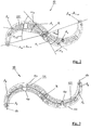
- FIGS 1 to 3 show an embodiment of a washing system 10 according to the invention, the washing system shown comprising a total of two washing arm segments.
- the washing system 10 is designed such that it can be rotated about an axis of rotation R when it is installed and operated in a dishwasher, in particular in a commercial dishwasher.
- the two wash arm segments 100 of the wash system 10 are seen in FIG Figures 1 to 3 , designed as an inverse S or question mark.
- the delivery elements A n are only arranged on one side, namely on the side facing the items to be washed after the washing system has been installed in a dishwasher.
- the delivery element that is closest to the axis of rotation R on a wash arm segment 100 is referred to as delivery element A 1
- the delivery element that is the greatest distance from the axis of rotation R is designated as delivery element A max (in the embodiment shown also delivery element A 10 ). That in the Figures 1 to 3
- the washing system 10 shown rotates when properly installed in a dishwasher, in the view shown in the figures, clockwise.
- each wash arm segment 100 which is in the direction of rotation or the direction of rotation of the wash system 10 or in the direction of movement of the wash arm segment 100, is therefore referred to as the front lateral delimitation 120, while the lateral delimitation, which is in the direction of rotation or direction of rotation of the wash system or in the direction of movement of the Wash arm segment is located at the rear, is referred to as the rear lateral boundary 140 of the respective wash arm segment 100.
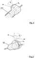
- Fig. 2 illustrates in particular the positioning of the delivery elements A n on the wash arm segments 100 and explains the interior angles ⁇ n .
- each wash arm segment 100 comprises a total of 10 delivery elements A 1 to A 10 , the delivery element A 1 being the delivery element which has the smallest distance r 1 from the axis of rotation R, while the delivery element A 10 (which corresponds to the delivery element A max ) is the delivery element that is at the greatest distance from the axis of rotation R.
- a connecting line between the axis of rotation R and a dispensing element forms an interior angle a with a connecting line between the axis of rotation R and another dispensing element.
- the washing arm segment shown on the left is shown, for example, the interior angle ⁇ 5 , which corresponds to the angle that, at the axis of rotation R, between a connecting line that extends from the axis of rotation R to the dispensing element A 1 and a connecting line that extends between the axis of rotation R and the delivery element A 5 extends, is formed.
- the interior angle ⁇ 5 which corresponds to the angle that, at the axis of rotation R, between a connecting line that extends from the axis of rotation R to the dispensing element A 1 and a connecting line that extends between the axis of rotation R and the delivery element A 5 extends, is formed.
- wash arm segment 100 On the right-hand side shown wash arm segment 100 is shown analogously an interior angle ⁇ 2 , which corresponds to the angle that, on the axis of rotation R, between a connecting line that extends from the axis of rotation R to the dispensing element A 1 and a connecting line that extends between the axis of rotation R and the delivery element A 2 is formed.
- the position of the dispensing element A 1 which is the smallest distance from the axis of rotation R, is therefore defined by the distance r 1 , while the relative positioning of all other dispensing elements A n relative to the first dispensing element A 1 is defined by the respective distance from the axis of rotation R. , namely r n , and by the corresponding interior angle ⁇ n .
- the interior angle ⁇ 1 which is assigned to the first output element A 1 , is always 0 °.
- the position of the delivery element A max which is at the greatest distance from the axis of rotation R, therefore defines the interior angle ⁇ max .
- the interior angle ⁇ max of the wash arm segment 100 which is shown in Fig. 2 shown on the right is greater than 75 ° and in this embodiment is about 80 °.
- two angles can also be defined between two connecting lines that meet in the axis of rotation R, the interior angle ⁇ n in the sense of this invention always being the smaller of the two angles.
- the other, larger angle which, however, was not referred to in the definition of this invention, has a size of 360 ° - ⁇ n .
- FIG. 13 shows a view in which a center line 130 is drawn in for each of the wash arm segments 100.
- the center line is determined in a top view or alternatively in a view from below, i.e. in a view parallel to the axis of rotation R, the center line being arranged in this view so that the distance from the center line is in a plane perpendicular to the axis of rotation R, in which the The center line runs, viewed, to a front lateral delimitation 120 of the wash arm segment is just as large as the distance to a rear lateral delimitation 140 of the wash arm segment 100.
- all the delivery members are in a range of the center line of the Why it is in a range of the center line of the Why it is in a range from the center line 130 starting in a direction towards the front lateral delimitation 120 of the wash arm segment 100.
- all dispensing elements A n are designed in the form of nozzles, the nozzles having an elongated dispensing opening so that a longitudinal axis of each dispensing opening is defined which extends in each case along the longest extent of the dispensing openings.
- the dispensing elements designed as nozzles are designed and arranged in such a way that, on each of the wash arm segments 100, the longitudinal axes of the dispensing openings of most of the dispensing elements A n extend so that they intersect the axis of rotation R.
- two delivery elements namely the delivery elements A 7 and A 9 , are designed in such a way that the longitudinal axes or their extensions do not intersect the axis of rotation R, rather the longitudinal axis of the delivery element A 7 is approximately 45 compared to such an arrangement ° rotated, while the longitudinal axis of the dispensing opening of the dispensing element A 9 is rotated approximately 90 ° with respect to such an orientation.
- Figure 4 shows a partial cross section through a wash arm segment of a washing system according to the invention, the partial cross section being guided through an area of the wash arm segment in which a delivery element A n is provided, which in this embodiment is designed as a nozzle.
- the nozzle is designed in such a way that it has an emission region which essentially has the shape of a cone, the opening angle of the cone being denoted by ⁇ 1.
- the opening angle ⁇ 1 can be identical for all delivery elements A n , which are arranged on a wash arm segment 100, but the opening angle can vary from nozzle to nozzle or also in the case of a nozzle as a function of the cutting plane. Preferred opening angles are in a range from 30 ° to 80 °, in particular in a range from 50 ° to 70 °. In the case of the Figure 4 The embodiment shown, the opening angle ⁇ 1 is just under 60 °.
- the dispensing device A n in this embodiment is designed in such a way that a central axis of the opening cone or a main emission direction of the dispensing area runs essentially perpendicularly, that is, parallel to the axis of rotation R.
- Fig. 5 shows another partial cross-section through a wash arm segment 100 of a washing system 10 according to the invention, a dispensing element A n also being provided in this cross-section.
- This delivery element A n also has an essentially conical delivery area, the cone having an opening angle of ⁇ 2 , which, in this embodiment, is just as large as ⁇ 1 , but in other embodiments can also be configured differently from ⁇ 1.
- a central axis of the opening cone or the radiation cone or a main radiation direction of the delivery area is tilted relative to the vertical, i.e. relative to the axis of rotation R, by an angle ⁇ 1 , which in this embodiment is about 30 °.
- the emission characteristics of the delivery elements A n can vary from one another, both by changing the opening angle ⁇ 1 , ⁇ 2 , and by changing the angle ⁇ 1 , at an angle relative to the axis of rotation R, with the nozzles also relative to the central axis, of course 180 can be rotated, which also changes the radiation characteristics in the case of non-symmetrical radiation areas of the nozzle.
Description
Die vorliegende Erfindung betrifft ein Waschsystem für eine Geschirrspülmaschine und eine Geschirrspülmaschine, die mit einem solchen Waschsystem ausgestattet ist.The present invention relates to a washing system for a dishwasher and a dishwasher which is equipped with such a washing system.
Ein Waschsystem ist typischerweise in der Form von sogenannten Wascharmen ausgebildet, die mit einem fluiden Medium, in der Regel einer Reinigungsflüssigkeit, beaufschlagt werden, wobei das fluide Medium dann über Abgabeelemente, insbesondere Düsen, abgegeben und auf das zu reinigende Geschirr geleitet wird.A washing system is typically designed in the form of so-called washing arms to which a fluid medium, usually a cleaning liquid, is applied, the fluid medium then being dispensed via dispensing elements, in particular nozzles, and directed onto the dishes to be cleaned.
Eine Geschirrspülmaschine umfasst mindestens ein solches Waschsystem, typischerweise werden aber mehrere solcher Waschsysteme oder Wascharme an verschiedenen Stellen in der Geschirrspülmaschine angeordnet, insbesondere unter und/oder über den Positionen in der Geschirrspülmaschine, in denen Geschirr zur Reinigung positioniert wird, beispielsweise in entsprechenden Waschkörben.A dishwasher comprises at least one such washing system, but typically several such washing systems or wash arms are arranged at different points in the dishwasher, in particular below and / or above the positions in the dishwasher in which dishes are positioned for cleaning, for example in corresponding washing baskets.
Ein Waschsystem bzw. Wascharm ist beweglich gelagert, wobei das Waschsystem bzw. der Wascharm während des Betriebs üblicherweise eine Drehbewegung um eine Rotationsachse ausführt, so dass ein Waschsystem bzw. ein Wascharm einen bestimmten Flächenbereich innerhalb der Geschirrspülmaschine abdeckt.A washing system or washing arm is movably mounted, the washing system or washing arm usually executing a rotary movement about an axis of rotation during operation, so that a washing system or washing arm covers a certain surface area within the dishwasher.
Ein solches Wachsystem ist beispielsweise aus der
Aus der
Aus der
Aus der
Aus der
Aus der
Basierend auf dem oben genannten Stand der Technik ist es eine Aufgabe der vorliegenden Erfindung, ein optimiertes Waschsystem zur Verfügung zu stellen, das besonders effektiv arbeitet und möglichst zuverlässig gute Spülerfolge erzielt.Based on the above-mentioned prior art, it is an object of the present invention to provide an optimized washing system which works particularly effectively and achieves good washing results as reliably as possible.
Diese Aufgabe wird durch ein Waschsystem für eine Geschirrspülmaschine, insbesondere für eine gewerbliche Geschirrspülmaschine, gemäß Anspruch 1, und eine Geschirrspülmaschine, insbesondere eine gewerbliche Geschirrspülmaschine, nach Anspruch 15 gelöst. Die Ansprüche 2 bis 14 betreffen besonders vorteilhafte Ausführungsformen eines Waschsystems gemäß Anspruch 1.This object is achieved by a washing system for a dishwasher, in particular for a commercial dishwasher, according to claim 1, and a dishwasher, in particular a commercial dishwasher, according to claim 15. Claims 2 to 14 relate to particularly advantageous embodiments of a washing system according to claim 1.
Gemäß der Erfindung wird ein Waschsystem für eine Geschirrspülmaschine zur Verfügung gestellt, das einen Wascharm umfasst, der um eine Drehachse R drehbar ist, wobei der Wascharm mindestens ein Wascharmsegment umfasst, das sich von der Drehachse R aus erstreckt. Das mindestens eine Wascharmsegment umfasst mehrere Abgabeelemente zur Abgabe eines fluiden Mediums, wobei gemäß der Erfindung jedes Wascharmsegment mindestens drei Abgabeelemente umfasst, d.h. insgesamt eine Anzahl N von Abgabeelementen umfasst, mit N ≥ 3. Jedes der Abgabeelemente ist mit Abstand von der Drehachse R angeordnet, so dass jedem Abgabeelement An ein zugehöriger Abstand rn zugewiesen ist, wobei dies für alle Abgabeelemente gilt, so dass n in einem Bereich von 1-N liegt (n = 1...N).According to the invention, a washing system for a dishwasher is provided which comprises a wash arm which is rotatable about an axis of rotation R, the wash arm comprising at least one wash arm segment which extends from the axis of rotation R. The at least one wash arm segment comprises several dispensing elements for dispensing a fluid medium, wherein according to the invention each wash arm segment comprises at least three dispensing elements, ie comprises a total of N number of dispensing elements, with N ≥ 3. Each of the dispensing elements is arranged at a distance from the axis of rotation R, so that an associated distance r n is assigned to each delivery element A n , this being true for all delivery elements, so that n lies in a range from 1-N (n = 1... N).
Die einzelnen Abgabeelemente eines Wascharmsegments sind auf unterschiedlichen Positionen des Wascharmsegments angeordnet, und zwar so, dass eine Verbindungslinie zwischen der Drehachse R und einem ersten Abgabeelement A1 des mindestens einem Wascharmsegments, das den kürzesten Abstand r1 aller Abgabeelemente An dieses Wascharmsegments zur Drehachse aufweist, mit einer Verbindungslinie zwischen der Drehachse R und einem anderen Abgabeelement An des selben Wascharmsegments einen Innenwinkel αn bildet.The individual delivery elements of a wash arm segment are arranged in different positions of the wash arm segment in such a way that a connecting line between the axis of rotation R and a first delivery element A 1 of the at least one wash arm segment which has the shortest distance r 1 of all delivery elements A n of this wash arm segment to the axis of rotation , with a connecting line between the axis of rotation R and another delivery element A n of the same wash arm segment forms an interior angle α n .
Die Position eines Abgabeelements An wird daher zum einen durch seinen Abstand rn von der Drehachse R und zum anderen von einer Winkelposition, relativ zu einer Winkelposition des Abgabeelements A1, das den kürzesten Abstand r1 aller Abgabeelemente aufweist, bestimmt, so dass jedem Abgabeelement An ein Abstand rn von der Drehachse R und ein Innenwinkel αn zugeordnet ist.The position of a delivery element A n is therefore determined on the one hand by its distance r n from the axis of rotation R and on the other hand by an angular position relative to an angular position of the delivery element A 1 , which has the shortest distance r 1 of all delivery elements, so that each Output element A n is assigned a distance r n from the axis of rotation R and an interior angle α n .
Gemäß der Erfindung gilt für jedes Abgabeelement An eines Wascharmsegments, dass ein zugehöriger Innenwinkel αn größer ist als ein Innenwinkel αn-1 eines anderen Abgabeelements An-1 des selben Wascharmsegments, wenn der Abstand rn des Abgabeelements An von der Drehachse R größer ist als der Abstand rn-1 des Abgabeelements An-1 von der Drehachse R.According to the invention, for each delivery element A n of a wash arm segment, an associated interior angle α n is greater than an interior angle α n-1 of another delivery element A n-1 of the same wash arm segment if the distance r n of the delivery element A n from the axis of rotation R is greater than the distance r n-1 of the delivery element A n-1 from the axis of rotation R.
In diesem Zusammenhang ist darauf hinzuweisen, dass im Hinblick auf zwei Verbindungslinien, einer Verbindungslinie zwischen der Drehachse R und einem ersten Abgabeelement und einer Verbindungslinie zwischen der Drehachse R und einem zweiten Abgabeelement auf demselben Wascharmsegment, die sich daher in der Drehachse R schneiden, zwei Winkel definiert werden können, die sich von ihrem Betrag unterscheiden, wenn die beiden Abgabeelemente nicht so angeordnet sind, dass sich die beiden Verbindungslinien parallel erstrecken. Unter einem Innenwinkel im Sinne der Erfindung ist jedoch immer der kleinere dieser beiden Winkel zu verstehen.In this context, it should be pointed out that with regard to two connecting lines, a connecting line between the axis of rotation R and a first dispensing element and a connecting line between the axis of rotation R and a second dispensing element on the same wash arm segment, which therefore intersect in the axis of rotation R, two angles can be defined that differ in their amount if the two delivery elements are not arranged so that the two connecting lines extend parallel. An interior angle within the meaning of the invention, however, is always to be understood as the smaller of these two angles.
Ein Waschsystem mit solchermaßen angeordneten Abgabeelementen hat den Vorteil, dass die Abgabeelemente optimal angeordnet sind, so dass zum einen eine ausreichende und gute Abdeckung der Bereiche der Geschirrspülmaschine, in denen Geschirr zur Reinigung positioniert wird, gewährleistet ist, während gleichzeitig sichergestellt werden kann, dass ein Überschneiden der Abgabebereiche der einzelnen Abgabeelemente, typischerweise Abgabekegel, stark vermindert und bevorzugt vollständig vermieden werden kann, zumindest bis zu einem bestimmten Abstand von den Abgabeelementen, der für das Spülen des in die Geschirrspülmaschine einzusetzenden Spülguts relevant ist, insbesondere der Abstand der Abgabeelemente zu den Positionen, in denen typischerweise das Spülgut in der Geschirrspülmaschine positioniert wird, bspw. in entsprechenden Waschkörben.A washing system with delivery elements arranged in this way has the advantage that the delivery elements are optimally arranged so that, on the one hand, sufficient and good coverage of the areas of the dishwasher in which dishes are positioned for cleaning is ensured, while at the same time it can be ensured that a Overlapping of the delivery areas of the individual delivery elements, typically delivery cones, can be greatly reduced and preferably completely avoided, at least up to a certain distance from the delivery elements that is relevant for washing the items to be washed in the dishwasher, in particular the distance between the delivery elements and the positions , in which the items to be washed are typically positioned in the dishwasher, for example in corresponding washing baskets.
Das Waschsystem stellt daher eine optimierte Verteilung der Abgabeelemente auf einem Wascharmsegment zur Verfügung, darüber hinaus hat eine solche Anordnung von Abgabeelementen in einem Wascharmsegment auch den Vorteil, dass eine Strömungsoptimierung bei der Zuführung des fluiden Mediums innerhalb eines Zuführkanals innerhalb des Wascharmsegments realisiert wird, die dazu führt, dass ein Überströmen von Düsen durch das fluide Medium innerhalb des Zuführkanals stark vermindert wird. Dadurch wird zum einen ein besonders verlustarmes System zur Verfügung gestellt, das damit Energie spart, zum anderen werden die Konstanz und die Qualität der Abgabe des fluiden Mediums durch die Abgabeelemente verbessert.The washing system therefore provides an optimized distribution of the dispensing elements on a wash arm segment; in addition, such an arrangement of dispensing elements in a wash arm segment also has the advantage that the flow is optimized when the fluid medium is supplied within a feed channel within the wash arm segment leads to an overflow of Nozzles is greatly reduced by the fluid medium within the feed channel. As a result, on the one hand, a particularly low-loss system is made available, which thus saves energy, and on the other hand, the constancy and the quality of the delivery of the fluid medium by the delivery elements are improved.
Insgesamt stellt daher das Waschsystem der vorliegenden Erfindung ein strömungsoptimiertes und damit energieeffizientes System zur Verfügung, das darüber hinaus bei weniger Aufwand, insbesondere bei geringerem energetischem Aufwand, verbesserte Spülergebnisse liefert.Overall, the washing system of the present invention therefore provides a flow-optimized and thus energy-efficient system which, moreover, delivers improved washing results with less effort, in particular with less energy expenditure.
Bevorzugt sind sämtliche Abgabeelemente auf einer Seite des Waschsystems angeordnet, nämlich auf der dem Spülgut zugewandten Seite. In besonderen Fällen ist es jedoch auch möglich, ein Waschsystem vorzusehen, das auf beiden Seiten, also oben und unten, Abgabeelemente aufweist, beispielsweise wenn ein Waschsystem so angeordnet ist, dass sowohl oberhalb als auch unterhalb des Waschsystems Spülgut angeordnet werden kann.All the dispensing elements are preferably arranged on one side of the washing system, namely on the side facing the items to be washed. In special cases, however, it is also possible to provide a washing system that has dispensing elements on both sides, i.e. above and below, for example when a washing system is arranged in such a way that items to be washed can be arranged both above and below the washing system.
Gemäß der Erfindung sind die Abgabeelemente auf einem Wascharmsegment so angeordnet, dass ein Innenwinkel αmax für das Abgabeelement Amax, das auf dem Wascharmsegment den größten Abstand rmax aller Abgabeelemente dieses Wascharmsegments von der Drehachse R aufweist, mindestens 60° beträgt. Bei einer besonders bevorzugten Ausführungsform beträgt dieser Winkel αmax bevorzugt mindestens 80°. Besonders bevorzugt liegt der Winkel αmax in einem Bereich von 60° bis 80°.According to the invention, the delivery elements are arranged on a wash arm segment in such a way that an interior angle α max for the delivery element A max , which on the wash arm segment has the greatest distance r max of all delivery elements of this wash arm segment from the axis of rotation R, is at least 60 °. In a particularly preferred embodiment, this angle α max is preferably at least 80 °. The angle α max is particularly preferably in a range from 60 ° to 80 °.
Auf diese Weise wird sichergestellt, dass der oben genannte Effekt besonders gut verwirklicht wird, ferner wird bereits ohne Bewegung bzw. Rotation des Waschsystems bereits ein großer Winkelbereich innerhalb einer Geschirrspülmaschine abgedeckt.In this way, it is ensured that the above-mentioned effect is achieved particularly well; furthermore, a large angular range within a dishwasher is already covered without moving or rotating the washing system.
Auch ist es, insbesondere bei der Abdeckung eines besonders großen Winkelbereichs, besonders gut möglich, Abgabeelemente so anzuordnen, dass ein Spülgut bzw. ein bestimmter Bereich eines Spülguts durch verschiedene Abgabeelemente eines einzelnen Wascharmsegments mit dem fluiden Medium beaufschlagt werden, ohne dass sich die Abgabeelemente gegenseitig beeinflussen bzw. sich die Abgabebereiche oder Abgabekegel der Abgabeelemente überschneiden.It is also particularly possible, especially when covering a particularly large angular range, to arrange dispensing elements in such a way that items to be washed or a specific Area of items to be washed are acted upon with the fluid medium by different dispensing elements of an individual wash arm segment without the dispensing elements influencing one another or the dispensing areas or dispensing cones of the dispensing elements overlapping.
Dadurch wird, mit sehr geringem energetischen Aufwand, sichergestellt, dass ein sehr gutes Spülergebnis erzielt werden kann, insbesondere auch weil bereits nach einmaligem Überstreichen eines bestimmten Bereichs innerhalb der Geschirrspülmaschine mit dem einen Wascharmsegment eine Beaufschlagung des Spülguts mittels zweier oder sogar mehrerer Abgabeelemente ermöglicht wird, wobei die mehrfache Beaufschlagung allerdings nicht gleichzeitig und damit sich gegenseitig beeinflussend, sondern, aufgrund der Position und Anordnung der Abgabeelemente auf dem Wascharmsegment, zeitlich versetzt stattfindet.This ensures, with very little energy expenditure, that a very good wash result can be achieved, in particular also because after a single wash over a certain area within the dishwasher with one wash arm segment, the items to be washed can be acted upon by means of two or even more dispensing elements, However, the multiple exposure does not take place simultaneously and thus mutually influencing, but rather takes place offset in time due to the position and arrangement of the delivery elements on the wash arm segment.
Gemäß einer besonderen Ausführungsform sind die Abgabeelemente auf einem Wascharmsegment so angeordnet, dass eine Differenz zwischen zwei Innenwinkeln αn und αn-1 für zwei unterschiedliche Abgabeelemente An und An-1 auf einem Wascharmsegment mindestens 2° beträgt. Bei besonders bevorzugten Ausführungsformen beträgt die Differenz sogar mindestens 3° oder sogar mindestens 5°.According to a particular embodiment, the delivery elements are arranged on a wash arm segment in such a way that a difference between two interior angles α n and α n-1 for two different delivery elements A n and A n-1 on a wash arm segment is at least 2 °. In particularly preferred embodiments, the difference is even at least 3 ° or even at least 5 °.
Bei besonders bevorzugten Ausführungsformen beträgt die Differenz zwischen zwei Innenwinkeln immer mindestens 2°, während jedoch bei zumindest einigen anderen Abgabeelementen die Differenz größer ist, beispielsweise mindestens 3° oder mindestens 5°, so dass Differenzen zwischen zwei Innenwinkeln zwischen "benachbarten" Abgabeelementen, also zwischen zwei Abgabeelementen, die den geringsten Unterschied im Hinblick auf ihren Abstand r von der Drehachse R aufweisen, immer mindestens 2° betragen, in einigen Fällen jedoch auch größer sind.In particularly preferred embodiments, the difference between two interior angles is always at least 2 °, while in at least some other delivery elements the difference is greater, for example at least 3 ° or at least 5 °, so that differences between two interior angles between "adjacent" delivery elements, i.e. between two delivery elements, which have the smallest difference in terms of their distance r from the axis of rotation R, always amount to at least 2 °, but in some cases are also larger.
Bei einer weiteren Ausführungsform sind die Abgabeelemente An auf einem Wascharmsegment bevorzugt jeweils in unterschiedlichen Abständen rn von der Drehachse R angeordnet, was eine besonders bevorzugte Verteilung der Abgabeelemente in radialer Richtung ermöglicht und daher die oben genannten Effekte verstärkt.In a further embodiment, the delivery elements A n on a wash arm segment are preferably each at different distances r n from the axis of rotation R arranged, which enables a particularly preferred distribution of the delivery elements in the radial direction and therefore intensifies the above-mentioned effects.
Bei einer besonderen Ausführungsform umfasst der Wascharm mindestens zwei Wascharmsegmente, die sich von der Drehachse R aus in unterschiedlichen Richtungen erstrecken, wobei bevorzugt genau zwei Wascharmsegmente vorgesehen sind, die sich von der Drehachse R aus in unterschiedliche Richtungen, insbesondere in entgegengesetzte Richtungen, erstrecken. Dies hat den Vorteil, dass der Wascharm eine besonders bevorzugte Gewichtsverteilung um die Drehachse R darstellt, was für die Rotationsbewegung günstig ist. Auch wird dadurch die Verteilung und das Zusammenwirken der Abgabeelemente auf den einzelnen Wascharmsegmente auf besonders vorteilhafte Weise unterstützt, so dass ein gutes Spülergebnis erzielt werden kann.In a particular embodiment, the wash arm comprises at least two wash arm segments, which extend from the axis of rotation R in different directions, preferably exactly two wash arm segments are provided, which extend from the axis of rotation R in different directions, in particular in opposite directions. This has the advantage that the wash arm represents a particularly preferred weight distribution around the axis of rotation R, which is favorable for the rotational movement. This also supports the distribution and interaction of the dispensing elements on the individual wash arm segments in a particularly advantageous manner, so that a good wash result can be achieved.
Bevorzugt ist das Waschsystem so ausgebildet, dass ein Querschnitt des Wascharms in einer Ebene senkrecht zur Drehachse R im Wesentlichen S-förmig ausgebildet ist. Dies bedeutet, dass der Wascharm bspw. in einer Draufsicht, also in einer Sicht auf den Wascharm in Richtung der Drehachse, S-förmig ausgebildet ist. In diesem Zusammenhang muss darauf hingewiesen werden, dass je nach Blickrichtung auf einen Wascharm, von unten oder von oben, bzw. je nachdem von welcher Seite der oben genannte Querschnitt betrachtet wird, der Wascharm S-förmig oder aber in Form eines inversen bzw. spiegelförmigen S ausgebildet ist.The washing system is preferably designed such that a cross section of the washing arm in a plane perpendicular to the axis of rotation R is essentially S-shaped. This means that the wash arm is S-shaped, for example in a plan view, that is to say in a view of the wash arm in the direction of the axis of rotation. In this context, it must be pointed out that depending on the direction of view of a wash arm, from below or from above, or depending on which side the above-mentioned cross-section is viewed from, the wash arm is S-shaped or in the form of an inverse or mirror-shaped one S is trained.
Eine solche Ausgestaltung des Wascharms führt dazu, dass der Wascharm, unter Berücksichtigung der speziellen Anordnung der Abgabeelemente gemäß dieser Erfindung, mit geringem Materialaufwand und damit mit geringem Gewicht hergestellt werden kann. Insbesondere in den Fällen, in denen der Innenwinkel αmax für das Abgabeelement Amax, das auf einem Wascharmsegment den größten Abstand rmax aufweist, sehr groß ist, beispielsweise 40° oder mehr beträgt, spielt dies eine erhöhte Rolle, was insbesondere dadurch deutlich wird, dass die (gedachte) Verbindungslinie zwischen der Drehachse R und dem Abgabeelement Amax, in der Draufsicht, also in Richtung der Drehachse R gesehen, weitgehend über Bereiche verläuft, die nicht über bzw. unter dem Wascharmsegment liegen, d.h. in diesem Bereich keinerlei Material des Wascharmsegments vorliegt, was das Gesamtgewicht reduziert.Such a design of the wash arm has the result that the wash arm, taking into account the special arrangement of the dispensing elements according to this invention, can be manufactured with little material expenditure and thus with low weight. In particular, in those cases in which the internal angle α max for the delivery element A max , which has the greatest distance r max on a wash arm segment, is very large, for example 40 ° or more, this plays an increased role, which becomes particularly clear that the (imaginary) connecting line between the axis of rotation R and the delivery element A max , seen in plan view, that is, in the direction of the axis of rotation R, largely over areas runs that are not above or below the wash arm segment, ie no material of the wash arm segment is present in this area, which reduces the overall weight.
Bei einer besonderen Ausführungsform ist die Anzahl des Abgabeelements und/oder die Position der Abgabeelemente auf einem Wascharmsegment unterschiedlich zu der Anzahl und/oder der Position der Abgabeelemente auf einem anderen Wascharmsegment des Waschsystems. Zwar ist es auch möglich, dass die einzelnen Wascharmsegmente im Hinblick auf den Abstand rn und den Innenwinkel αn identisch ausgebildet sind, allerdings führt eine unterschiedliche Anordnung der Abgabeelemente auf einzelnen Wascharmsegmenten dazu, dass das Spülgut von jedem der Wascharmsegmente unterschiedlich mit dem fluiden Medium beaufschlagt wird, was das Spülergebnis noch weiter verbessert.In a particular embodiment, the number of dispensing elements and / or the position of the dispensing elements on one wash arm segment is different from the number and / or the position of the dispensing elements on another wash arm segment of the washing system. Although it is also possible for the individual wash arm segments to be identical with regard to the distance r n and the interior angle α n , a different arrangement of the dispensing elements on individual wash arm segments means that the wash ware of each of the wash arm segments differs with the fluid medium is acted upon, which improves the washing result even further.
Bei einer besonderen Ausführungsform umfasst jedes Wascharmsegment einen als Hohlraum ausgebildeten Zuführkanal zur Aufnahme eines fluiden Mediums und zur Zuführung des fluiden Mediums zu den Abgabeelementen, wobei der Zuführkanal so ausgebildet ist, dass sich der Querschnitt des Zuführkanals in einer Ebene senkrecht zu einer Tangente einer Mittellinie des Wascharmsegments mit zunehmendem Abstand von der Drehachse R verjüngt. Die Verjüngung kann dabei kontinuierlich erfolgen, es ist allerdings auch möglich, dass eine stufenweise Verjüngung vorgesehen ist, auch ist es möglich, dass die Verjüngung teilweise kontinuierlich und teilweise über Stufen erfolgt. Unter der Mittellinie ist in diesem Sinne dieser Erfindung eine Linie zu verstehen, die sich, in Draufsicht auf das Waschsystem in Richtung der Drehachse R, ausgehend von der Drehachse R in einer Ebene, die senkrecht zur Drehachse R verläuft, in beide Richtungen der Erstreckung der Wascharmsegmente so erstreckt, dass der Abstand der Mittellinie zu einer vorderen Kante des Wascharmsegments genauso groß ist wie der Abstand der Mittellinie zu einer hinteren Kante des Wascharmsegments. Die Mittellinie teilt daher die Wascharmsegmente, im Hinblick auf eine Querschnittsebene oder Betrachtungsebene, die senkrecht zur Drehachse R verläuft, in zwei weitgehend gleichgroße Teilbereiche.In a particular embodiment, each wash arm segment comprises a feed channel designed as a cavity for receiving a fluid medium and for feeding the fluid medium to the delivery elements, the feed channel being designed so that the cross section of the feed channel extends in a plane perpendicular to a tangent to a center line of the Wash arm segment tapers with increasing distance from the axis of rotation R. The tapering can take place continuously, but it is also possible that a gradual tapering is provided, it is also possible that the tapering takes place partly continuously and partly via steps. In this sense of this invention, the center line is to be understood as a line which, in a plan view of the washing system in the direction of the axis of rotation R, starting from the axis of rotation R in a plane that runs perpendicular to the axis of rotation R, extends in both directions of the extent of the Wash arm segments extends so that the distance between the center line and a front edge of the wash arm segment is the same as the distance between the center line and a rear edge of the wash arm segment. The center line therefore divides the wash arm segments, with regard to a cross-sectional plane or viewing plane that runs perpendicular to the axis of rotation R, into two largely equal partial areas.
Diese Ausgestaltung hat den Vorteil, dass möglichst gleichmäßige Strömungsgeschwindigkeiten erzeugt werden, sodass Turbulenzen innerhalb des Zuführkanals weitgehend vermieden werden.This refinement has the advantage that flow speeds that are as uniform as possible are generated, so that turbulence within the feed channel is largely avoided.
Bevorzugt ist die Verjüngung des Zuführkanals mit zunehmenden Abstand von der Drehachse in einem Ausmaß ausgebildet, das im Wesentlichen proportional zur Abnahme eines Volumenstroms des fluiden Mediums, mit zunehmendem Abstand von der Drehachse, ist, die durch die Abgabe des fluiden Mediums durch die Abgabeelemente hervorgerufen wird. Dadurch wird besonders effektiv sichergestellt, dass die Strömungsgeschwindigkeit innerhalb des Zuführkanals weitgehend konstant bleibt. Die dadurch hervorgerufene Vermeidung oder zumindest Verminderung von Turbulenzen führt zum einen dazu, dass das Waschsystem energetisch günstiger ist, ferner dazu, dass die Abgabecharakteristik der Abgabeelemente besonders exakt gesteuert und eingehalten werden kann, ferner sehr geringe Fluktuationen der Abgabecharakteristik entstehen.Preferably, the tapering of the supply channel with increasing distance from the axis of rotation is formed to an extent that is essentially proportional to the decrease in a volume flow of the fluid medium, with increasing distance from the axis of rotation, which is caused by the delivery of the fluid medium by the delivery elements . This ensures in a particularly effective way that the flow rate within the feed channel remains largely constant. The resulting avoidance or at least reduction of turbulence leads, on the one hand, to the washing system being energetically more favorable, and also to the fact that the delivery characteristics of the delivery elements can be controlled and maintained particularly precisely, and there are very slight fluctuations in the delivery characteristics.
Bei einer besonders bevorzugten Ausführungsform sind alle Abgabeelemente des Wascharmsegmentes in einem Bereich von einer Mittellinie des Wascharmsegmentes bis zu einer seitlichen Begrenzung des Wascharmsegments angeordnet, die in Rotationsrichtung des Wascharmes oder in Bewegungsrichtung eines Wascharmsegments vorne liegt. Diese Anordnung der Abgabeelemente in einem Randbereich hat insbesondere den Effekt, dass ein Überströmen der Abgabeelemente durch das fluide Medium in dem Zuführkanal weiter reduziert wird, was die energetische Effizienz und das zu erzielende Spülergebnis weiter verbessert.In a particularly preferred embodiment, all delivery elements of the wash arm segment are arranged in an area from a center line of the wash arm segment to a lateral boundary of the wash arm segment, which is at the front in the direction of rotation of the wash arm or in the direction of movement of a wash arm segment. This arrangement of the dispensing elements in an edge region has the effect, in particular, that the fluid medium in the feed channel further reduces the overflow of the dispensing elements, which further improves the energetic efficiency and the washing result to be achieved.
Bevorzugt sind die Abgabeelemente als Düsen ausgebildet, wobei ferner bevorzugt zumindest nicht alle Düsen eines Wascharmsegments oder eines Waschsystems die gleiche Abstrahlcharakteristik aufweisen.The delivery elements are preferably designed as nozzles, and at least not all of the nozzles of a wash arm segment or of a wash system preferably have the same emission characteristics.
Die Abstrahlcharakteristik einer Düse kann zum einen durch die räumliche Positionierung und die Stellung der Düse beeinflusst werden. Der Abstrahlbereich, bei dem es sich typischerweise um einen Abstrahlkegel oder einen Abstrahlfächer handelt, kann zwar im Wesentlichen rotationssymmetrisch sein, er kann aber auch nicht rotationssymmetrisch sein, sodass auch eine Rotation der Düse um ihre Achsen die Abstrahlcharakteristik verändert. Eine Auswahl unterschiedlicher Abstrahlcharakteristiken von Düsen ermöglicht es daher, im Zusammenhang mit der besonderen Positionierung der Abgabeelemente auf einem Wascharmsegment, eine gute Abdeckung der verschiedenen Bereiche der Geschirrspülmaschine sicherzustellen, beispielsweise auch Abgabeelemente dichter anzuordnen, wobei dennoch ein Überlappen der Abstrahlbereiche und eine gegenseitige negative Beeinflussung der Abstrahlbereiche, die dadurch hervorgerufen würde, zu vermeiden.The radiation characteristics of a nozzle can be influenced on the one hand by the spatial positioning and the position of the nozzle. The radiation area, which is typically a radiation cone or a radiation fan, can be essentially rotationally symmetrical, but it can also not be rotationally symmetrical, so that a rotation of the nozzle around its axis also changes the radiation characteristics. A selection of different radiation characteristics of nozzles therefore makes it possible, in connection with the special positioning of the delivery elements on a wash arm segment, to ensure good coverage of the different areas of the dishwasher, for example also to arrange delivery elements more densely, with an overlap of the radiation areas and a mutual negative influence of the Avoid radiation areas that would be caused by this.
Bevorzugt sind die Abgabeelemente in einem äußeren Bereich des Wascharmsegments dichter angeordnet als in einem inneren Bereich des Wascharmsegments. Dies ist bevorzugt, weil aufgrund der Rotationsbewegung des Waschsystems während des Spülvorgangs die radial äußeren Bereiche eine größere Fläche und einen größeren Bereich abdecken müssen als die radial innen liegenden Bereiche. Auf diese Weise kann ein gleichmäßig gutes Spülergebnis erzielt wird, unabhängig davon, an welcher Stelle innerhalb der Geschirrspülmaschine sich das Spülgut befindet, beispielsweise in einem äußeren Bereich eines Spülkorbs oder in einem inneren Bereich.The delivery elements are preferably arranged more densely in an outer region of the wash arm segment than in an inner region of the wash arm segment. This is preferred because, due to the rotational movement of the washing system during the rinsing process, the radially outer areas must cover a larger area and a larger area than the radially inner areas. In this way, a consistently good washing result can be achieved, regardless of where the items to be washed are located within the dishwasher, for example in an outer area of a washing basket or in an inner area.
Eine solche Verdichtung von Abgabeelementen in einem äußeren Bereich kann sowohl bei einem einzelnen Wascharmsegment vorgesehen werden, eine Verdichtung in einem äußeren Bereich ist jedoch insbesondere auch im Hinblick auf mehrere, zusammenwirkende Wascharmsegmente beziehungsweise ein gesamtes Waschsystem mit unterschiedlichen Wascharmsegmenten bevorzugt.Such a compression of delivery elements in an outer area can be provided both for a single wash arm segment, however, compression in an outer area is also particularly preferred with regard to several interacting wash arm segments or an entire wash system with different wash arm segments.
Gemäß einer besonderen Ausführung des erfindungsgemäßen Waschsystems ist mindestens ein Abgabeelement An so ausgebildet und auf einem Wascharmsegment angeordnet, dass eine Hauptabstrahlrichtung oder eine Mittelachse des Abgabebereichs relativ zu Drehachse R um einen Winkel (γ1) gekippt ist.According to a particular embodiment of the washing system according to the invention, at least one delivery element A n is designed and arranged on a wash arm segment such that a main radiation direction or a central axis of the delivery area is tilted relative to the axis of rotation R by an angle (γ 1).
Dies hat den Vorteil, dass eine noch bessere Abdeckung der Bereiche der Geschirrspülmaschine sichergestellt wird, wobei ein Überlappen der Abgabebereiche der Abgabeelemente vermieden werden kann. Ferner kann dadurch zusätzlich sichergestellt werden, dass ein Antrieb des Waschsystems durch die Rückstrahlkraft der entsprechend angeordneten Abgabeelemente gewährleistet oder unterstützt wird.This has the advantage that an even better coverage of the areas of the dishwasher is ensured, it being possible to avoid overlapping of the delivery areas of the delivery elements. Furthermore, this can also be ensured that a drive of the washing system is guaranteed or supported by the reflecting force of the correspondingly arranged dispensing elements.
Gemäß einer weiteren bevorzugten Ausführungsform des erfindungsgemäßen Waschsystems sind mindestens zwei Abgabeelemente An auf einem Wascharmsegment als Düsen ausgebildet, wobei die Düsen jeweils eine längliche Abgabeöffnung aufweisen, so dass eine Längsachse jeder der Abgabeöffnungen definiert wird, die sich in Richtung der längsten Ausdehnung der Abgabeöffnung erstreckt, wobei die beiden Abgabeelemente so angeordnet sind, dass die Längsachsen der beiden Abgabeelemente nicht parallel zueinander verlaufen und eine Längsachse mindestens einer Abgabeöffnung so liegt, dass sie bzw. ihre Verlängerung nicht die Drehachse R schneidet.According to a further preferred embodiment of the washing system according to the invention, at least two dispensing elements A n are designed as nozzles on a wash arm segment, the nozzles each having an elongated dispensing opening so that a longitudinal axis of each of the dispensing openings is defined, which extends in the direction of the longest extent of the dispensing opening , the two dispensing elements being arranged in such a way that the longitudinal axes of the two dispensing elements do not run parallel to one another and a longitudinal axis of at least one dispensing opening lies in such a way that it or its extension does not intersect the axis of rotation R.
Auch diese unterschiedliche Ausgestaltung der Abgabeelemente führt dazu, dass eine Überlappung der Abstrahlbereiche noch besser vermieden werden kann, gleichzeitig aber sämtliche relevanten Bereiche der Geschirrspülmaschine zuverlässig abgedeckt werden, so dass ein sehr gutes Spülergebnis erzielt werden kann.This different design of the dispensing elements also means that overlapping of the radiation areas can be avoided even better, but at the same time all relevant areas of the dishwasher are reliably covered so that a very good washing result can be achieved.
Die vorliegende Erfindung betrifft auch eine Geschirrspülmaschine, insbesondere eine gewerbliche Geschirrspülmaschine, die mindestens ein Waschsystem nach einem der vorhergehenden Ansprüche umfasst.The present invention also relates to a dishwasher, in particular a commercial dishwasher, which comprises at least one washing system according to one of the preceding claims.
Wie bereits erwähnt umfasst eine Geschirrspülmaschine in der Regel mehrere Waschsysteme, die bevorzugt unter und/oder über beispielsweise Waschkörben angeordnet sind, in die Spülgut innerhalb einer Geschirrspülmaschine eingesetzt werden kann.As already mentioned, a dishwasher generally comprises a plurality of washing systems, which are preferably arranged below and / or above, for example, washing baskets, into which items to be washed can be inserted within a dishwasher.
Eine besonders bevorzugte Geschirrspülmaschine umfasst beispielsweise zwei Spülkörbe, wobei ein erstes Waschsystem unter einem unteren Spülkorb angeordnet ist, während ein zweites Waschsystem zwischen den beiden Spülkörben angeordnet ist, und wobei gegebenenfalls zusätzlich ein weiteres Waschsystem über dem oberen Spülkorb angeordnet ist.A particularly preferred dishwasher comprises, for example, two washing racks, with a first washing system being arranged under a lower washing rack, while a second washing system is arranged between the two washing racks, and with an additional washing system optionally being arranged above the upper washing rack.
Bei einer solchen Geschirrspülmaschine weist das Waschsystem, das unter dem unteren Spülkorb angeordnet ist, sodass Spülgut lediglich oberhalb des Waschsystems positioniert werden kann, Abgabeelemente, insbesondere Düsen, lediglich auf seiner Oberseite auf. Analog weist ein Waschsystem, das so angeordnet ist, dass Spülgut lediglich unter diesem Waschsystem in der Geschirrspülmaschine positioniert werden kann, Abgabeelemente nur an seiner Unterseite auf. Waschsysteme, die so angeordnet, dass Spülgut sowohl oberhalb als auch unterhalb positioniert werden kann, weisen bevorzugt Abgabeelemente sowohl an der Oberseite als auch an der Unterseite auf.In such a dishwasher, the washing system, which is arranged below the lower washing rack, so that items to be washed can only be positioned above the washing system, only has dispensing elements, in particular nozzles, on its upper side. Analogously, a washing system which is arranged in such a way that items to be washed can only be positioned under this washing system in the dishwasher has dispensing elements only on its underside. Washing systems which are arranged in such a way that items to be washed can be positioned both above and below, preferably have dispensing elements on both the top and the bottom.
Diese und weitere Merkmale und Vorteile der vorliegenden Erfindung werden anhand der nachfolgenden Figuren, die besonders bevorzugte Ausführungsformen der Erfindung zeigen, deutlich:
- Figs. 1
bis 3 - zeigen eine Ausführungsform eines erfindungsgemäßen Waschsystems,
- Fig. 4
- zeigt einen Teilquerschnitt eines Wascharmsegments eines erfindungsgemäßen Waschsystems mit einem Abgabeelement; und
- Fig. 5
- zeigt einen anderen Teilquerschnitt eines Wascharmsegments eines erfindungsgemäßen Waschsystems mit einem anderen Abgabeelement.
- Figs. 1 to 3
- show an embodiment of a washing system according to the invention,
- Fig. 4
- shows a partial cross-section of a wash arm segment of a wash system according to the invention with a dispensing element; and
- Fig. 5
- shows another partial cross-section of a wash arm segment of a wash system according to the invention with a different dispensing element.
Die
Das Waschsystem 10 ist so ausgebildet, dass es um eine Drehachse R gedreht werden kann, wenn es in einer Geschirrspülmaschine, insbesondere in einer gewerblichen Geschirrspülmaschine, eingebaut ist und betrieben wird.The
Die zwei Wascharmsegmente 100 des Waschsystems 10 sind, in der Ansicht der
Bei den in den
In diesem Zusammenhang soll auch darauf hingewiesen werden, dass es prinzipiell auch möglich ist, dass eine andere Ausführungsform eines Waschsystems Abgabeelemente An auf beiden Seiten, sowohl auf einer Oberseite als auch auf einer Unterseite, aufweist, so dass eine Wasch- oder Spülflüssigkeit in beide Richtungen abgegeben werden kann.In this context, it should also be pointed out that it is in principle also possible for another embodiment of a washing system to have dispensing elements A n on both sides, both on an upper side and on a lower side, so that a washing or rinsing liquid in both Directions can be given.
Das Abgabeelement, das auf einem Wascharmsegment 100 den geringsten Abstand zur Drehachse R aufweist, wird als Abgabeelement A1 bezeichnet, das Abgabeelement, das den größten Abstand von der Drehachse R aufweist, wird als Abgabeelement Amax bezeichnet (bei der gezeigten Ausführungsform auch Abgabeelement A10). Das in den
Wie in
Auf dem in
Die Position des Abgabeelements A1, das den geringsten Abstand zur Drehachse R aufweist, wird daher durch den Abstand r1 definiert, während die relative Positionierung aller anderer Abgabeelemente An relativ zum ersten Abgabeelement A1 definiert wird, durch den jeweiligen Abstand zur Drehachse R, nämlich rn, und durch den entsprechenden Innenwinkel αn. In diesem Sinne beträgt der Innenwinkel α1, der dem ersten Abgabeelements A1 zugeordnet ist, immer 0°.The position of the dispensing element A 1 , which is the smallest distance from the axis of rotation R, is therefore defined by the distance r 1 , while the relative positioning of all other dispensing elements A n relative to the first dispensing element A 1 is defined by the respective distance from the axis of rotation R. , namely r n , and by the corresponding interior angle α n . In this sense, the interior angle α 1 , which is assigned to the first output element A 1 , is always 0 °.
Die Position des Abgabeelements Amax, das den größten Abstand von der Drehachse R aufweist, definiert daher den Innenwinkel αmax. Wie oben erläutert, umfasst das Wascharmsegment 100, das in
Der Innenwinkel αmax des Wascharmsegments 100, das in
Wie bereits oben erläutert, können zwischen zwei Verbindungslinien, die in der Drehachse R zusammentreffen, auch jeweils zwei Winkel definiert werden, wobei der Innenwinkel αn im Sinne dieser Erfindung immer der kleinere der beiden Winkel ist. Der andere, größere Winkel, auf den bei der Definition dieser Erfindung jedoch nicht Bezug genommen worden ist, hat daher eine Größe von 360° - αn.As already explained above, two angles can also be defined between two connecting lines that meet in the axis of rotation R, the interior angle α n in the sense of this invention always being the smaller of the two angles. The other, larger angle, which, however, was not referred to in the definition of this invention, has a size of 360 ° -α n .
Wie in
Wie ebenfalls in
Bei dieser Ausführungsform sind die als Düsen ausgebildeten Abgabeelemente so ausgebildet und angeordnet, dass sich, auf jedem der Wascharmsegmente 100, die Längsachsen der Abgabeöffnungen der meisten Abgabeelemente An so erstrecken, dass sie die Drehachse R schneiden. Auf jedem Wascharmsegment 100 sind jedoch zwei Abgabeelemente, nämlich jeweils die Abgabeelemente A7 und A9, so ausgebildet, dass die Längsachsen oder ihre Verlängerungen nicht die Drehachse R schneiden, vielmehr ist die Längsachse des Abgabeelements A7 gegenüber einer solchen Anordnung in etwa um 45° gedreht, während die Längsachse der Abgabeöffnung des Abgabeelements A9 gegenüber einer solchen Ausrichtung in etwa um 90° gedreht ist.In this embodiment, the dispensing elements designed as nozzles are designed and arranged in such a way that, on each of the
Dies verhindert eine Überlappung der Abgabebereiche benachbarter Abgabeelemente und sorgt daher für ein besonders gutes Spülergebnis.This prevents the dispensing areas of adjacent dispensing elements from overlapping and therefore ensures a particularly good wash result.
Der Öffnungswinkel β1 kann für alle Abgabeelement An, die auf einem Wascharmsegment 100 angeordnet sind, identisch sein, der Öffnungswinkel kann jedoch von Düse zu Düse oder auch bei einer Düse in Abhängigkeit von der Schnittebene variieren. Bevorzugte Öffnungswinkel liegen in einem Bereich von 30° bis 80°, insbesondere in einem Bereich von 50° bis 70°. Bei der in der
Wie in
Auch dieses Abgabeelement An weist einen im Wesentlichen kegelförmigen Abgabebereich auf, wobei der Kegel einen Öffnungswinkel von β2 aufweist, der, bei dieser Ausführungsform, genauso groß ist wie β1, bei anderen Ausführungsformen aber auch von β1 unterschiedlich ausgebildet sein kann.This delivery element A n also has an essentially conical delivery area, the cone having an opening angle of β 2 , which, in this embodiment, is just as large as β 1 , but in other embodiments can also be configured differently from β 1.
Wie in
Wie bereits erläutert, können die Abstrahlcharakteristiken der Abgabeelemente An voneinander variieren, sowohl durch Änderungen des Öffnungswinkels β1, β2, als auch durch Änderung des Winkels γ1, in einem Winkel relativ zur Drehachse R, wobei natürlich die Düsen auch relativ zur Mittelachse 180 gedreht werden können, was bei nicht symmetrischen Abstrahlbereichen der Düse ebenfalls die Abstrahlcharakteristik verändert.As already explained, the emission characteristics of the delivery elements A n can vary from one another, both by changing the opening angle β 1 , β 2 , and by changing the angle γ 1 , at an angle relative to the axis of rotation R, with the nozzles also relative to the central axis, of
Die in der Beschreibung, den Ansprüchen und den Figuren offenbarten Merkmale der Erfindung können sowohl einzeln als auch in beliebiger Kombination für die Verwirklichung der Erfindung wesentlich sein.The features of the invention disclosed in the description, the claims and the figures can be essential for the implementation of the invention both individually and in any combination.
Claims (15)
- Washing system for a dishwasher, which comprises a washing arm which is rotatable about an axis of rotation R, wherein the washing arm comprises at least one washing arm segment which extends out from the axis of rotation R,
wherein the at least one washing arm segment comprises N dispensing elements for dispensing a fluid medium, where N ≥ 3, wherein each dispensing element An is arranged spaced apart from the axis of rotation R at a distance rn, where n = 1...N,
wherein a connection line between the axis of rotation R and a first dispensing element A1 of the at least one washing arm segment, which has the shortest distance r1 of all dispensing elements An of this washing arm segment to axis of rotation R, forms in each case an internal angle αn, where n = 2 ... N, with a connection line between the axis of rotation R and that of the other dispensing element An of the same washing arm segment, where n = 2 ... N,
wherein an internal angle αn is greater for each dispensing element An, where n = 2 ... N, of a washing arm segment than an internal angle αn-1 for another dispensing element An-1, where n = 2 ... N, of the same washing arm segment, if the distance rn of the dispensing element An from the axis of rotation R is greater than the distance rn-1 of the dispensing element An-1 from the axis of rotation R, characterized in that the dispensing elements are arranged on the washing arm segment such that a difference between two internal angles αn and αn-1 for two different dispensing elements An and An-1 on the washing arm segment is at least 2°, and
the dispensing elements are arranged on the washing arm segment such that the internal angle αmax for the dispensing element Amax, which, of all dispensing elements on this washing arm segment, has the greatest distance rmax on this washing arm segment from the axis of rotation R, is at least 60°. - Washing system according to claim 1, characterized in that the dispensing elements are arranged on a washing arm segment such that a difference between two internal angles αn and αn-1 for two different dispensing elements An and An-1 on the washing arm segment is at least 3°, preferably at least 5°.
- Washing system according to one of the preceding claims, characterized in that the dispensing elements An on one washing arm segment are respectively arranged at different distances rn from the axis of rotation R.
- Washing system according to one of the preceding claims, characterized in that the washing arm comprises at least two washing arm segments, preferably exactly two washing arm segments, which extend in different directions from the axis of rotation R.
- Washing system according to claim 4, characterized in that a cross section of the washing arm is designed to be substantially S-shaped or in the form of a mirror-image S in a plane perpendicular to the axis of rotation R.
- Washing system according to one of claims 4 to 5, characterized in that the number of dispensing elements and/or the position of the dispensing elements on a washing arm segment differs from the number of dispensing elements and/or the position of the dispensing elements on another washing arm segment.
- Washing system according to one of the preceding claims, characterized in that each washing arm segment has a supply channel, designed as a cavity, for accommodating a fluid medium and for supplying the fluid medium to the dispensing elements, wherein the cross section of the supply channel tapers in a plane perpendicular to a tangent of a center line of the washing arm segment as the distance from the axis of rotation R increases.
- Washing system according to claim 7, characterized in that the tapering of the supply channel takes place by an amount, which is substantially proportional to the decrease of a volume flow of the fluid medium at an increasing distance from the axis of rotation, which decrease of the volume flow is caused by the dispensing of the fluid medium by the dispensing elements.
- Washing system according to one of the preceding claims, characterized in that all dispensing elements An of a washing arm segment lie in an area from a center line of the washing arm segment, which runs in a plane perpendicular to the axis of rotation R, up to a lateral boundary of the washing arm segment, which lies at the front in the movement direction of the washing arm segment.
- Washing system according to one of the preceding claims, characterized in that at least one of the dispensing elements, preferably all dispensing elements, is/are designed as nozzles, wherein preferably at least one nozzle has a different emission characteristic as another nozzle on the same washing arm segment.
- Washing system according to one of the preceding claims, characterized in that, for at least one washing arm segment, the dispensing elements are positioned such that fewer dispensing elements are arranged in the area of the washing arm segment, which extends from the axis of rotation R out to one-half of the maximum radial extension of the washing arm segment, than in the area of the washing arm segment, which extends from one-half of the maximum radial extension of the washing arm segment to the maximum radial extension of the washing arm segment.
- Washing system according to one of the preceding claims, characterized in that the washing arm segments are designed such that fewer dispensing elements are arranged in the areas of the washing arm segments, which extend from the axis of rotation R out to one-half of the maximum radial extension of the washing system, than in the areas of the washing arm segments, which extend from one-half of the maximum radial extension of the washing system to the maximum radial extension of the washing system.
- Washing system according to one of the preceding claims, characterized in that at least one dispensing element An is designed and arranged on a washing arm segment such that a main emission direction or a center axis of the dispensing area of the dispensing element An is tilted by an angle (γ1) relative to the axis of rotation R.
- Washing system according to one of the preceding claims, characterized in that at least two dispensing elements An are designed on a washing arm segment as nozzles, wherein the nozzles each have an elongated dispensing opening, wherein a longitudinal axis is defined for each of the dispensing openings and extends in the direction of the longest extension of the dispensing opening, wherein the two dispensing elements are arranged such that the longitudinal axes of the two dispensing elements do not run parallel to one another, and the longitudinal axis of at least one dispensing opening lies such that it does not intersect with the axis of rotation R.
- Dishwasher, in particular a commercial dishwasher, which comprises at least one washing system according to one of the preceding claims.
Applications Claiming Priority (1)
| Application Number | Priority Date | Filing Date | Title |
|---|---|---|---|
| DE102015111811.4A DE102015111811B4 (en) | 2015-07-21 | 2015-07-21 | Washing system for a dishwasher, and dishwasher with such a washing system |
Publications (2)
| Publication Number | Publication Date |
|---|---|
| EP3120747A1 EP3120747A1 (en) | 2017-01-25 |
| EP3120747B1 true EP3120747B1 (en) | 2021-08-25 |
Family
ID=56497678
Family Applications (1)
| Application Number | Title | Priority Date | Filing Date |
|---|---|---|---|
| EP16180467.9A Active EP3120747B1 (en) | 2015-07-21 | 2016-07-21 | Washing system for a dishwasher, and dishwasher with such a washing system |
Country Status (3)
| Country | Link |
|---|---|
| EP (1) | EP3120747B1 (en) |
| DE (1) | DE102015111811B4 (en) |
| ES (1) | ES2890679T3 (en) |
Family Cites Families (10)
| Publication number | Priority date | Publication date | Assignee | Title |
|---|---|---|---|---|
| IT1240721B (en) | 1990-09-06 | 1993-12-17 | Merloni Elettrodomestici Spa | DISHWASHER MACHINE PERFECTED |
| DE10205008A1 (en) | 2002-02-07 | 2003-08-21 | Electrolux Home Prod Corp | dishwasher |
| US6869029B2 (en) * | 2002-04-02 | 2005-03-22 | Distinctive Appliances, Inc. | Water spray system for a dishwasher |
| EP2571416B1 (en) | 2010-05-19 | 2021-12-29 | Electrolux Home Products Corporation N.V. | Arrangement in a dishwasher |
| DE102010051218A1 (en) | 2010-11-12 | 2012-05-16 | Belimed Ag | Washing arm for a cleaning machine for cleaning medical, pharmaceutical and / or laboratory utensils |
| US20120279536A1 (en) * | 2011-05-04 | 2012-11-08 | Whirlpool Corporation | Dishwasher spray arm with diverting valve |
| US20120285496A1 (en) * | 2011-05-09 | 2012-11-15 | General Electric Company | Dishwasher spray assembly |
| US9179818B2 (en) * | 2012-05-01 | 2015-11-10 | General Electric Company | Spray arm assembly for a dishwasher appliance |
| DE102012104026B4 (en) | 2012-05-08 | 2019-01-17 | Winterhalter Gastronom Gmbh | Dishwashing machine and dishwasher with such a dishwashing system |
| CN203447254U (en) * | 2013-07-10 | 2014-02-26 | 美的集团股份有限公司 | Gushing arm waterway connecting structure and dish washing machine |
-
2015
- 2015-07-21 DE DE102015111811.4A patent/DE102015111811B4/en active Active
-
2016
- 2016-07-21 EP EP16180467.9A patent/EP3120747B1/en active Active
- 2016-07-21 ES ES16180467T patent/ES2890679T3/en active Active
Non-Patent Citations (1)
| Title |
|---|
| None * |
Also Published As
| Publication number | Publication date |
|---|---|
| DE102015111811A1 (en) | 2017-01-26 |
| EP3120747A1 (en) | 2017-01-25 |
| DE102015111811B4 (en) | 2017-02-09 |
| ES2890679T3 (en) | 2022-01-21 |
Similar Documents
| Publication | Publication Date | Title |
|---|---|---|
| DE112005000830B4 (en) | Dispenser of a detergent supply device for a washing machine | |
| DE102005015156A1 (en) | Transport dishwashing machine and spray pipe for it | |
| DE19832982A1 (en) | Dishwashing device for a dishwasher | |
| DE19608030C1 (en) | Industrial dishwashing machine | |
| EP2888394A1 (en) | Device for hydrodynamically strengthening nonwovens, wovens or knitted fabrics | |
| DE7024995U (en) | Dishwasher | |
| EP2601877B1 (en) | Dishwasher with automatic reversal of the direction of rotation of the spray arm | |
| EP2601878B1 (en) | Dishwasher with automatic reversal of the direction of rotation of the spray arm | |
| EP3120747B1 (en) | Washing system for a dishwasher, and dishwasher with such a washing system | |
| EP1681976B1 (en) | Device for controlling spray channels in dishwasher machines | |
| EP2353732B2 (en) | Dispensing bar | |
| DE1926826U (en) | SPRAY DEVICE FOR AUTOMATIC DISHWASHING MACHINES. | |
| EP2868818B1 (en) | Sink assembly | |
| EP3815595B1 (en) | Transport dishwasher | |
| EP2695566B1 (en) | Dishwasher | |
| EP3375564B1 (en) | Machine tool and method for operating same | |
| EP3362329B1 (en) | Vehicle washing system | |
| DE202013105662U1 (en) | Device for positioning a standing person in the center of a nozzle arrangement | |
| EP3747340B1 (en) | Washing basket for dishwashers | |
| DE202017105653U1 (en) | Wire eroding machine for cutting biscuits | |
| DE202009017787U1 (en) | Device for applying a surface layer to cores | |
| DE2536411C3 (en) | Dishwasher for cleaning ring-shaped objects | |
| EP2952129B1 (en) | Sieve system for a dishwasher, and dishwasher with such a sieve system | |
| DE60038718T2 (en) | Device for controlling the amount of regeneration salt taken from the salt reservoir of the softener device of a washing machine | |
| DE102021006330A1 (en) | cleanser |
Legal Events
| Date | Code | Title | Description |
|---|---|---|---|
| PUAI | Public reference made under article 153(3) epc to a published international application that has entered the european phase |
Free format text: ORIGINAL CODE: 0009012 |
|
| STAA | Information on the status of an ep patent application or granted ep patent |
Free format text: STATUS: REQUEST FOR EXAMINATION WAS MADE |
|
| 17P | Request for examination filed |
Effective date: 20161010 |
|
| AK | Designated contracting states |
Kind code of ref document: A1 Designated state(s): AL AT BE BG CH CY CZ DE DK EE ES FI FR GB GR HR HU IE IS IT LI LT LU LV MC MK MT NL NO PL PT RO RS SE SI SK SM TR |
|
| AX | Request for extension of the european patent |
Extension state: BA ME |
|
| STAA | Information on the status of an ep patent application or granted ep patent |
Free format text: STATUS: EXAMINATION IS IN PROGRESS |
|
| 17Q | First examination report despatched |
Effective date: 20170614 |
|
| STAA | Information on the status of an ep patent application or granted ep patent |
Free format text: STATUS: EXAMINATION IS IN PROGRESS |
|
| REG | Reference to a national code |
Ref country code: DE Ref legal event code: R079 Ref document number: 502016013680 Country of ref document: DE Free format text: PREVIOUS MAIN CLASS: A47L0015230000 Ipc: A47L0015420000 |
|
| GRAP | Despatch of communication of intention to grant a patent |
Free format text: ORIGINAL CODE: EPIDOSNIGR1 |
|
| STAA | Information on the status of an ep patent application or granted ep patent |
Free format text: STATUS: GRANT OF PATENT IS INTENDED |
|
| RIC1 | Information provided on ipc code assigned before grant |
Ipc: A47L 15/42 20060101AFI20210203BHEP Ipc: A47L 15/23 20060101ALI20210203BHEP |
|
| INTG | Intention to grant announced |
Effective date: 20210309 |
|
| GRAS | Grant fee paid |
Free format text: ORIGINAL CODE: EPIDOSNIGR3 |
|
| GRAA | (expected) grant |
Free format text: ORIGINAL CODE: 0009210 |
|
| STAA | Information on the status of an ep patent application or granted ep patent |
Free format text: STATUS: THE PATENT HAS BEEN GRANTED |
|
| AK | Designated contracting states |
Kind code of ref document: B1 Designated state(s): AL AT BE BG CH CY CZ DE DK EE ES FI FR GB GR HR HU IE IS IT LI LT LU LV MC MK MT NL NO PL PT RO RS SE SI SK SM TR |
|
| REG | Reference to a national code |
Ref country code: CH Ref legal event code: EP |
|
| REG | Reference to a national code |
Ref country code: DE Ref legal event code: R096 Ref document number: 502016013680 Country of ref document: DE |
|
| REG | Reference to a national code |
Ref country code: IE Ref legal event code: FG4D Free format text: LANGUAGE OF EP DOCUMENT: GERMAN Ref country code: AT Ref legal event code: REF Ref document number: 1422929 Country of ref document: AT Kind code of ref document: T Effective date: 20210915 |
|
| REG | Reference to a national code |
Ref country code: LT Ref legal event code: MG9D |
|
| REG | Reference to a national code |
Ref country code: NL Ref legal event code: MP Effective date: 20210825 |
|
| REG | Reference to a national code |
Ref country code: ES Ref legal event code: FG2A Ref document number: 2890679 Country of ref document: ES Kind code of ref document: T3 Effective date: 20220121 |
|
| PG25 | Lapsed in a contracting state [announced via postgrant information from national office to epo] |
Ref country code: HR Free format text: LAPSE BECAUSE OF FAILURE TO SUBMIT A TRANSLATION OF THE DESCRIPTION OR TO PAY THE FEE WITHIN THE PRESCRIBED TIME-LIMIT Effective date: 20210825 Ref country code: RS Free format text: LAPSE BECAUSE OF FAILURE TO SUBMIT A TRANSLATION OF THE DESCRIPTION OR TO PAY THE FEE WITHIN THE PRESCRIBED TIME-LIMIT Effective date: 20210825 Ref country code: SE Free format text: LAPSE BECAUSE OF FAILURE TO SUBMIT A TRANSLATION OF THE DESCRIPTION OR TO PAY THE FEE WITHIN THE PRESCRIBED TIME-LIMIT Effective date: 20210825 Ref country code: FI Free format text: LAPSE BECAUSE OF FAILURE TO SUBMIT A TRANSLATION OF THE DESCRIPTION OR TO PAY THE FEE WITHIN THE PRESCRIBED TIME-LIMIT Effective date: 20210825 Ref country code: PT Free format text: LAPSE BECAUSE OF FAILURE TO SUBMIT A TRANSLATION OF THE DESCRIPTION OR TO PAY THE FEE WITHIN THE PRESCRIBED TIME-LIMIT Effective date: 20211227 Ref country code: NO Free format text: LAPSE BECAUSE OF FAILURE TO SUBMIT A TRANSLATION OF THE DESCRIPTION OR TO PAY THE FEE WITHIN THE PRESCRIBED TIME-LIMIT Effective date: 20211125 Ref country code: LT Free format text: LAPSE BECAUSE OF FAILURE TO SUBMIT A TRANSLATION OF THE DESCRIPTION OR TO PAY THE FEE WITHIN THE PRESCRIBED TIME-LIMIT Effective date: 20210825 Ref country code: BG Free format text: LAPSE BECAUSE OF FAILURE TO SUBMIT A TRANSLATION OF THE DESCRIPTION OR TO PAY THE FEE WITHIN THE PRESCRIBED TIME-LIMIT Effective date: 20211125 |
|
| PG25 | Lapsed in a contracting state [announced via postgrant information from national office to epo] |
Ref country code: PL Free format text: LAPSE BECAUSE OF FAILURE TO SUBMIT A TRANSLATION OF THE DESCRIPTION OR TO PAY THE FEE WITHIN THE PRESCRIBED TIME-LIMIT Effective date: 20210825 Ref country code: LV Free format text: LAPSE BECAUSE OF FAILURE TO SUBMIT A TRANSLATION OF THE DESCRIPTION OR TO PAY THE FEE WITHIN THE PRESCRIBED TIME-LIMIT Effective date: 20210825 Ref country code: GR Free format text: LAPSE BECAUSE OF FAILURE TO SUBMIT A TRANSLATION OF THE DESCRIPTION OR TO PAY THE FEE WITHIN THE PRESCRIBED TIME-LIMIT Effective date: 20211126 |
|
| PG25 | Lapsed in a contracting state [announced via postgrant information from national office to epo] |
Ref country code: NL Free format text: LAPSE BECAUSE OF FAILURE TO SUBMIT A TRANSLATION OF THE DESCRIPTION OR TO PAY THE FEE WITHIN THE PRESCRIBED TIME-LIMIT Effective date: 20210825 |
|
| PG25 | Lapsed in a contracting state [announced via postgrant information from national office to epo] |
Ref country code: DK Free format text: LAPSE BECAUSE OF FAILURE TO SUBMIT A TRANSLATION OF THE DESCRIPTION OR TO PAY THE FEE WITHIN THE PRESCRIBED TIME-LIMIT Effective date: 20210825 |
|
| REG | Reference to a national code |
Ref country code: DE Ref legal event code: R097 Ref document number: 502016013680 Country of ref document: DE |
|
| PG25 | Lapsed in a contracting state [announced via postgrant information from national office to epo] |
Ref country code: SM Free format text: LAPSE BECAUSE OF FAILURE TO SUBMIT A TRANSLATION OF THE DESCRIPTION OR TO PAY THE FEE WITHIN THE PRESCRIBED TIME-LIMIT Effective date: 20210825 Ref country code: SK Free format text: LAPSE BECAUSE OF FAILURE TO SUBMIT A TRANSLATION OF THE DESCRIPTION OR TO PAY THE FEE WITHIN THE PRESCRIBED TIME-LIMIT Effective date: 20210825 Ref country code: RO Free format text: LAPSE BECAUSE OF FAILURE TO SUBMIT A TRANSLATION OF THE DESCRIPTION OR TO PAY THE FEE WITHIN THE PRESCRIBED TIME-LIMIT Effective date: 20210825 Ref country code: EE Free format text: LAPSE BECAUSE OF FAILURE TO SUBMIT A TRANSLATION OF THE DESCRIPTION OR TO PAY THE FEE WITHIN THE PRESCRIBED TIME-LIMIT Effective date: 20210825 Ref country code: CZ Free format text: LAPSE BECAUSE OF FAILURE TO SUBMIT A TRANSLATION OF THE DESCRIPTION OR TO PAY THE FEE WITHIN THE PRESCRIBED TIME-LIMIT Effective date: 20210825 Ref country code: AL Free format text: LAPSE BECAUSE OF FAILURE TO SUBMIT A TRANSLATION OF THE DESCRIPTION OR TO PAY THE FEE WITHIN THE PRESCRIBED TIME-LIMIT Effective date: 20210825 |
|
| PLBE | No opposition filed within time limit |
Free format text: ORIGINAL CODE: 0009261 |
|
| STAA | Information on the status of an ep patent application or granted ep patent |
Free format text: STATUS: NO OPPOSITION FILED WITHIN TIME LIMIT |
|
| 26N | No opposition filed |
Effective date: 20220527 |
|
| PG25 | Lapsed in a contracting state [announced via postgrant information from national office to epo] |
Ref country code: SI Free format text: LAPSE BECAUSE OF FAILURE TO SUBMIT A TRANSLATION OF THE DESCRIPTION OR TO PAY THE FEE WITHIN THE PRESCRIBED TIME-LIMIT Effective date: 20210825 |
|
| PG25 | Lapsed in a contracting state [announced via postgrant information from national office to epo] |
Ref country code: MC Free format text: LAPSE BECAUSE OF FAILURE TO SUBMIT A TRANSLATION OF THE DESCRIPTION OR TO PAY THE FEE WITHIN THE PRESCRIBED TIME-LIMIT Effective date: 20210825 |
|
| REG | Reference to a national code |
Ref country code: BE Ref legal event code: MM Effective date: 20220731 |
|
| PG25 | Lapsed in a contracting state [announced via postgrant information from national office to epo] |
Ref country code: LU Free format text: LAPSE BECAUSE OF NON-PAYMENT OF DUE FEES Effective date: 20220721 |
|
| PG25 | Lapsed in a contracting state [announced via postgrant information from national office to epo] |
Ref country code: BE Free format text: LAPSE BECAUSE OF NON-PAYMENT OF DUE FEES Effective date: 20220731 |
|
| P01 | Opt-out of the competence of the unified patent court (upc) registered |
Effective date: 20230421 |
|
| PG25 | Lapsed in a contracting state [announced via postgrant information from national office to epo] |
Ref country code: IE Free format text: LAPSE BECAUSE OF NON-PAYMENT OF DUE FEES Effective date: 20220721 |
|
| REG | Reference to a national code |
Ref country code: AT Ref legal event code: MM01 Ref document number: 1422929 Country of ref document: AT Kind code of ref document: T Effective date: 20220721 |
|
| PG25 | Lapsed in a contracting state [announced via postgrant information from national office to epo] |
Ref country code: AT Free format text: LAPSE BECAUSE OF NON-PAYMENT OF DUE FEES Effective date: 20220721 |
|
| PGFP | Annual fee paid to national office [announced via postgrant information from national office to epo] |
Ref country code: IT Payment date: 20230721 Year of fee payment: 8 Ref country code: GB Payment date: 20230725 Year of fee payment: 8 Ref country code: ES Payment date: 20230816 Year of fee payment: 8 Ref country code: CH Payment date: 20230801 Year of fee payment: 8 |
|
| PGFP | Annual fee paid to national office [announced via postgrant information from national office to epo] |
Ref country code: FR Payment date: 20230725 Year of fee payment: 8 Ref country code: DE Payment date: 20230726 Year of fee payment: 8 |
|
| PG25 | Lapsed in a contracting state [announced via postgrant information from national office to epo] |
Ref country code: HU Free format text: LAPSE BECAUSE OF FAILURE TO SUBMIT A TRANSLATION OF THE DESCRIPTION OR TO PAY THE FEE WITHIN THE PRESCRIBED TIME-LIMIT; INVALID AB INITIO Effective date: 20160721 |