EP1585657B1 - Dispositif d'essuie-glace de vehicules automobiles - Google Patents
Dispositif d'essuie-glace de vehicules automobiles Download PDFInfo
- Publication number
- EP1585657B1 EP1585657B1 EP03773482A EP03773482A EP1585657B1 EP 1585657 B1 EP1585657 B1 EP 1585657B1 EP 03773482 A EP03773482 A EP 03773482A EP 03773482 A EP03773482 A EP 03773482A EP 1585657 B1 EP1585657 B1 EP 1585657B1
- Authority
- EP
- European Patent Office
- Prior art keywords
- wiper
- wiper strip
- cap
- wiping device
- spring
- Prior art date
- Legal status (The legal status is an assumption and is not a legal conclusion. Google has not performed a legal analysis and makes no representation as to the accuracy of the status listed.)
- Expired - Lifetime
Links
Images


Classifications
-
- B—PERFORMING OPERATIONS; TRANSPORTING
- B60—VEHICLES IN GENERAL
- B60S—SERVICING, CLEANING, REPAIRING, SUPPORTING, LIFTING, OR MANOEUVRING OF VEHICLES, NOT OTHERWISE PROVIDED FOR
- B60S1/00—Cleaning of vehicles
- B60S1/02—Cleaning windscreens, windows or optical devices
- B60S1/04—Wipers or the like, e.g. scrapers
- B60S1/32—Wipers or the like, e.g. scrapers characterised by constructional features of wiper blade arms or blades
- B60S1/38—Wiper blades
- B60S1/3848—Flat-type wiper blade, i.e. without harness
- B60S1/3886—End caps
- B60S1/3887—Mounting of end caps
- B60S1/3891—Mounting of end caps with locking device
-
- B—PERFORMING OPERATIONS; TRANSPORTING
- B60—VEHICLES IN GENERAL
- B60S—SERVICING, CLEANING, REPAIRING, SUPPORTING, LIFTING, OR MANOEUVRING OF VEHICLES, NOT OTHERWISE PROVIDED FOR
- B60S1/00—Cleaning of vehicles
- B60S1/02—Cleaning windscreens, windows or optical devices
- B60S1/04—Wipers or the like, e.g. scrapers
- B60S1/32—Wipers or the like, e.g. scrapers characterised by constructional features of wiper blade arms or blades
- B60S1/38—Wiper blades
- B60S1/3806—Means, or measures taken, for influencing the aerodynamic quality of the wiper blades
- B60S1/381—Spoilers mounted on the squeegee or on the vertebra
-
- B—PERFORMING OPERATIONS; TRANSPORTING
- B60—VEHICLES IN GENERAL
- B60S—SERVICING, CLEANING, REPAIRING, SUPPORTING, LIFTING, OR MANOEUVRING OF VEHICLES, NOT OTHERWISE PROVIDED FOR
- B60S1/00—Cleaning of vehicles
- B60S1/02—Cleaning windscreens, windows or optical devices
- B60S1/04—Wipers or the like, e.g. scrapers
- B60S1/32—Wipers or the like, e.g. scrapers characterised by constructional features of wiper blade arms or blades
- B60S1/38—Wiper blades
- B60S2001/3812—Means of supporting or holding the squeegee or blade rubber
- B60S2001/3822—Means of supporting or holding the squeegee or blade rubber characterised by additional means to prevent longitudinal sliding of squeegee in support, e.g. clips
Definitions
- the invention relates to a wiper device for windows of motor vehicles with the features mentioned in the preamble of patent claim 1.
- a wiper blade for windows of motor vehicles are known.
- Such a wiper blade typically consists of a wiper strip which is stiffened by means of one or two spring rails and which has a wiper lip which can be applied to the window.
- the curvature and the spring properties of the wiper strip reinforcing spring rails significantly determine the adaptability of the wiper lip to the curvature of the windshield and thus the wiping properties of the wiper blade.
- the wiper blade is fixed approximately centrally by means of an adapter or a coupling part releasably attached to a pivotable wiper arm of the motor vehicle.
- a wiper strip is provided with two laterally mounted spring rails, which are integrally connected to each other at their two ends by means of transverse webs.
- Such one-piece wiper blades are for example in the DE 296 11 722 U1 and in the DE 100 25 710 A1 described. Characteristic here is the permanent connection of the two spring rails with the wiper strip.
- a wiper device for windows of motor vehicles consists of a jointless wiper blade with a wiper strip, a wiper lip arranged thereon and a coupling part connectable to the wiper blade for detachable connection to a pivotable wiper arm of the vehicle.
- the wiper strip has a profile with guide grooves for laterally receiving two spring rails, which are connected to each other at their two ends.
- the invention provides that the wiper strip has a locking device which fixes the spring rails in the wiper strip in a locked position, and which allows in an unlocked position a longitudinal displacement of the spring rails in the guide grooves of the wiper strip.
- the wiper blade made of rubber or other suitable flexible material can be separated from the spring rails and replaced separately when worn.
- the spring rails are firmly connected to the wiper blade and can not be separated from it non-destructively.
- the invention allows a resource-saving replacement of only the used components of the wiper device.
- the locking device comprises a fixable on an upper side of the wiper strip fastening clip, which acts in releasable latching connection with a connecting bridge connecting the spring rails together.
- the fastening clip can be connected to the base strip by means of tabs engaging in the guide grooves and at least one hook which can be pressed into the upper side of a base section of the wiper strip.
- the flat mounting clip in the locked state the connecting bridge partially engage, being locked by means of stop hooks and a spring tongue against the connecting bridge.
- the lock can be released by pressing the elastically deformable spring tongue against the upper side of the base section of the wiper strip.
- the spring rails are each connected in one piece at their ends here, in the present case by means of a connecting bridge. In this way, it is ensured that the spring rails can not be moved apart and are thus fixed at any time laterally fixed in the profile of the wiper strip.
- the wiper strip can be longitudinally be moved against the spring rails when the locking of the mounting clip is released with the connecting bridge.
- the lock consists of stop hooks of the mounting clip, which rest against one edge of the connecting bridge. At its opposite edge is in the locked state, the flexible spring tongue, which can be pushed by pressing down on the wiper strip from the edge away.
- the fastening clip can dip under a longitudinal displacement of the wiper strip against the spring rails under the connecting bridge and the wiper strip can be completely separated in a sliding movement in the longitudinal direction of the spring rails. These slide in a first guide groove on both sides of the wiper strip.
- An embodiment of the invention provides that the lock is releasable by actuation of a securing bracket, which is mounted in a cap located at the end of the wiper blade.
- the cap has a cooperating with the spring tongue, elastically deformable locking cams, which actuates the spring tongue when removing the cap.
- the locking cam also ensures that the cap can only be deducted by a certain amount of force and can not be lost during normal operation of the wiper device. If the cap is still lost, the lock is not solved automatically, but can be solved manually if necessary.
- the actuation of the locking device takes place in this embodiment by removing the cap from the wiper blade.
- An alternative embodiment provides that the lock is releasable by actuation of a securing bracket, which is mounted in a cap located at the end of the wiper blade.
- the cap in this case has a slightly different shape and function and remains even when unlocking the wiper blade.
- the cap is fixed by means of at least one substantially rigid latching cam on the connecting bridge.
- the spring tongue is in this embodiment of the invention during pivoting of the securing bracket by a befmdlichen on this unlocking bracket operable.
- Both alternative embodiments may further provide that the cap has two slide rails, which engage respectively in the guide grooves of the wiper strip.
- the cap has two slide rails, which engage respectively in the guide grooves of the wiper strip.
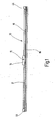
- a wiper device 10 comprises a wiper blade 12 which consists of a wiper strip 16 and a wiper lip 18 formed integrally therewith (cf. FIG. 1 ).
- the wiper lip 18 serves to clean a window of a motor vehicle.
- a coupling member 14 is mounted approximately centrally on the wiper blade 12 and serves for releasable connection with a pivotable wiper arm (not shown).
- the coupling part 14 has a hinge pin 15 whose longitudinal axis is aligned perpendicular to the longitudinal direction of the wiper blade 12.
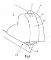
- the wiper blade 12 has a cap 44 whose function is based on the FIGS. 7 to 13 is explained in more detail.
- the wiper blade 12 has a substantially symmetrical profile with a plurality of oppositely disposed guide grooves 24, 26, which are arranged in the wiper strip 16 below one of the wiper lip 18 opposite base portion 25 (see. FIG. 2 ).
- the provided below the base portion 25 first guide grooves 24 serve to receive two spring rails 20, which ensure the desired dimensional stability and Elastin activity of the wiper blade 12 when sweeping the disc.
- the spring rails 20 each consist of a flat, band-like element, which has an approximately rectangular cross-section - and that is largely elastically deformable only in the direction parallel to its narrow sides. Depending on the application, the spring rails 20 can already have a predetermined curvature in the relaxed state.
- the two spring rails 20 each protrude from the first guide groove 24 and are connected to each other at their ends by means of a connecting bridge 22 (see. FIG. 3 ).
- the distance between the two spring rails 20 is kept substantially constant over the entire length thereof by the two connecting bridges 22 welded at the ends.
- Spring rails 20 and connecting bridges 22 may, for example, consist of spring steel or of an elastic plastic, which preferably has a fiber reinforcement.
- the base portion 25 is located between each of the guide rails 20 and the connecting bridge 22, wherein a small distance for insertion of a flat fastening clips 30 (see. Figures 5 and 6 ) remains.
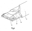
- first guide grooves 24 second guide grooves 26 can be seen, in which possibly a spoiler cover 17 can engage.
- this surrounds the wiper strip 16 only indirectly and is hooked in the laterally protruding from the first guide grooves 24 sections of the spring rails 20 (see. Figures 2 . 4 and 6 ), so that it remains at a separation of the wiper strip 16 of the spring rails 20 at this.
- the spoiler cover 17 is optional and can optionally be omitted.
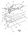
- the mounting clip 30 may be attached to one end of the wiper strip 16 as shown in FIG FIG. 5 is clarified.
- the disk-shaped, preferably made of sheet metal or plastic fastening clip 30 has two lateral tabs 36 which can be bent laterally around the base portion 25 around.
- a spiked hook 32 can be seen on a region pointing towards the end of the wiper strip 16 which, when the fastening clip 30 is pressed in, penetrates vertically into the upper side 23 of the base section 25 and remains there.
- the pointed hook 32 has two barbs 34 which can get caught in the rubber of the wiper strip 16.
- two short, vertically upwardly facing stop hooks 40 can be seen, which can provide in conjunction with a, arranged in a central region of the mounting clip 30 spring tongue 42 for releasable connection with one of the connecting bridges 22.
- At one end of the hook 32 and the stop hook 40 opposite end of the clip 30 is shaped like a spade 38. This contour of the clip 30 facilitates the mounting of the wiper strip 16 by facilitating the insertion of the fastening clip 30 under the connecting bridge 22.
- FIG. 6 illustrates a locked position of the mounting clip 30, the stop hooks 40 abut against a front edge of the connecting bridge 22 and the relaxed spring tongue 42 abuts against the opposite edge of the connecting bridge 22.
- the wiper strip 16 provided with the fastening clip 30 is thus firmly connected to the two spring rails 20.
- the spring tongue 42 is pressed down on the top 23 of the base portion 25. In this position, the wiper strip 16 and the mounting clip 30 to the left (corresponding to FIG. 6 ) are pulled out under the connecting bridge 22.
- the invention provides an actuator in the form of a cap 44 for easier release of the clip 30 before.
- the cap 44 has two slide rails 50, which engage in the first or second guide grooves 24, 26 and can engage around the spring rails 20.
- a hood 48 of the cap 44 is preferably adapted to the contour of the spoiler cover 17.
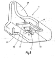
- a first variant of the cap 44 according to the FIGS. 7 and 8th has an elastically deformable locking cam 46 which is located at completely pushed onto the end of the wiper strip 16 cap 44 behind the spring tongue 42 and exerts no force on this.
- the cap 44 is in this case pushed with a stop pin 52 against the wiper strip 16 and the connecting bridge 22.
- the locking cam 46 is suspended elastically by means of a leaf spring and protrudes downward from a cover plate 58, which can form a further stop for the cap 44 by resting on the connecting bridge 22.
- the locking cam 46 has a rear ramp 54 with a ramp angle 56 of, for example, about 75 degrees. Such a ramp angle 56 ensures that the locking cam 46 can slide over the connecting bridge 22 and 44 is not blocked there when removing the cap.
- the spring tongue 42 is actuated by the locking cam 46 pressing thereon, so that the wiper strip 16 can be separated by the spring clip 20 with the fixing clip 30 fixed thereto by a longitudinal displacement.
- the spring stiffness of the spring tongue 42 must be less than that of the suspension of the locking cam 46, so that it is not pushed up before the spring tongue 42 has been pressed below the level of the connecting bridge 22. This mechanism allows for easy separation of a wiper strip 16 with spent wiper lip 18 from the reusable spring rails 20, without having to replace the entire wiper blade 12.
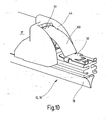
- FIGS. 9 to 13 An alternative embodiment of an unlocking device arranged in the cap 44 is in the FIGS. 9 to 13 illustrated.
- the cap 44 has a pivotally mounted securing bracket 60, which can be adapted in its contour of the curved surface of the cap and pivoted in an elongated recess 59 by a limited angle of about 25 degrees.
- a gripping surface 61 in the upper region of the securing bracket 60 By pressing on a gripping surface 61 in the upper region of the securing bracket 60, the latter can be moved from a locked position (FIG. FIG. 9 ) in an unlocked position ( Figures 10 and 11 ) to be brought.
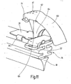
- the securing bracket 60 laterally has two pivot bearings 62 which are mounted on pivot axes 68 (cf. Figures 12 and 13 ) of the cap 44 are rotatably mounted.
- each locking recesses 71 are provided, engage in the corresponding locking projections 72 of the cap 44 and provide a latching of the securing bracket 60 in its normal position.
- An abutment step 66 at the lower end of Entriegelungsbügels 64 finds a stop on the connecting bridge 22, whereby the pivot angle of the securing bracket 60 is limited (see. FIG. 11 ).
- FIG. 10 shows the mounting clip 30 dipping under the cap after it has been unlocked by operation of the bracket 60.
- the cap 44 remains firmly connected in this alternative variant with the spring rails 20 and the spoiler cover 17.
- An ironing stop 70 on the one hand forms a support for the locked bracket 60 and at the same time constitutes a stop for the cap 44, since the ironing stop 70 bears against the edge of the connecting bridge 22 lying opposite the locking cam 46.
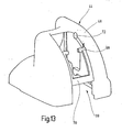
- FIG. 13 illustrates again the second variant of the cap 44 without the arranged in the recess 59 securing bracket 60th
- the illustrated caps 44 may be selectively attached to both ends of the wiper blade 12, but only one of the caps has the functions described.
- the other cap serves only for covering and optical covering of the connecting bridge having an end of the wiper blade.
Abstract
Claims (9)
- Dispositif d'essuie-glace pour des vitres de véhicules automobiles, constitué d'un balai d'essuie-glace non articulé avec une raclette de balai d'essuie-glace, une lèvre de balai d'essuie-glace disposée sur celle-ci, et une partie d'accouplement pouvant être connectée au balai d'essuie-glace, pour la connexion desserrable à un bras d'essuie-glace pivotant du véhicule, la raclette de balai d'essuie-glace comprenant un profilé avec des rainures de guidage pour recevoir latéralement deux rails élastiques, qui sont connectés à chaque fois l'un à l'autre à leurs deux extrémités, la raclette de balai d'essuie-glace (16) présentant un dispositif de verrouillage qui, dans une position verrouillée, fixe les rails élastiques (20) dans la raclette de balai d'essuie-glace (16), et qui, dans une position déverrouillée, permet un coulissement longitudinal des rails élastiques (20) dans les rainures de guidage (24) de la raclette de balai d'essuie-glace (16), le dispositif de verrouillage comprenant une pince de fixation (30) pouvant être fixée sur un côté supérieur (23) de la raclette de balai d'essuie-glace (16), qui coopère dans une connexion d'encliquetage desserrable avec un pont de connexion (22) reliant les rails élastiques (20), caractérisé en ce que la pince de fixation (30) peut être connectée à la raclette de balai d'essuie-glace (16) au moyen de pattes (36) venant en prise dans les rainures de guidage (24) de la raclette de balai d'essuie-glace (16) et d'au moins un crochet pointu (32) pouvant être enfoncé dans le côté supérieur (23) d'une portion de base (25).
- Dispositif d'essuie-glace selon la revendication 1, caractérisé en ce que la pince de fixation (30) vient en prise en partie sous le pont de connexion (22) dans la position verrouillée et est verrouillée au moyen de crochets de butée (40) et d'une langue à ressort (42) contre le pont de connexion (22).
- Dispositif d'essuie-glace selon la revendication 2, caractérisé en ce que le verrouillage peut être desserré par pression de la langue à ressort (42) déformable élastiquement contre le côté supérieur (23) de la portion de base (25) de la raclette de balai d'essuie-glace (16).
- Dispositif d'essuie-glace selon la revendication 3, caractérisé en ce que le verrouillage peut être desserré en enlevant un capuchon (44) de l'extrémité du balai d'essuie-glace (12).
- Dispositif d'essuie-glace selon la revendication 3 ou 4, caractérisé en ce que le capuchon (44) présente une came d'encliquetage (46) déformable élastiquement coopérant avec la langue à ressort (42), qui actionne la langue à ressort (42) lors du retrait du capuchon (44).
- Dispositif d'essuie-glace selon la revendication 3, caractérisé en ce que le verrouillage peut être desserré par l'actionnement d'un étrier de fixation (60) monté dans un capuchon (44) se trouvant à l'extrémité du balai d'essuie-glace (12).
- Dispositif d'essuie-glace selon la revendication 6, caractérisé en ce que la langue à ressort (42) peut être actionnée lors du pivotement de l'étrier de fixation (60) par un étrier de déverrouillage (64) se trouvant sur celui-ci.
- Dispositif d'essuie-glace selon la revendication 6 ou 7, caractérisé en ce que le capuchon (44) est fixé au moyen d'au moins une came d'encliquetage essentiellement rigide (46) sur le pont de connexion (22).
- Dispositif d'essuie-glace selon l'une quelconque des revendications 4 à 8, caractérisé en ce que le capuchon (44) présente deux rails coulissants (50) venant respectivement en prise dans les rainures de guidage (24) de la raclette de balai d'essuie-glace (16).
Applications Claiming Priority (3)
| Application Number | Priority Date | Filing Date | Title |
|---|---|---|---|
| DE10259478 | 2002-12-19 | ||
| DE10259478A DE10259478A1 (de) | 2002-12-19 | 2002-12-19 | Wischvorrichtung für Scheiben von Kraftfahrzeugen |
| PCT/DE2003/003276 WO2004056623A1 (fr) | 2002-12-19 | 2003-10-02 | Dispositif d'essuie-glace de vehicules automobiles |
Publications (2)
| Publication Number | Publication Date |
|---|---|
| EP1585657A1 EP1585657A1 (fr) | 2005-10-19 |
| EP1585657B1 true EP1585657B1 (fr) | 2011-03-02 |
Family
ID=32403950
Family Applications (1)
| Application Number | Title | Priority Date | Filing Date |
|---|---|---|---|
| EP03773482A Expired - Lifetime EP1585657B1 (fr) | 2002-12-19 | 2003-10-02 | Dispositif d'essuie-glace de vehicules automobiles |
Country Status (5)
| Country | Link |
|---|---|
| US (1) | US7581280B2 (fr) |
| EP (1) | EP1585657B1 (fr) |
| JP (1) | JP4732759B2 (fr) |
| DE (2) | DE10259478A1 (fr) |
| WO (1) | WO2004056623A1 (fr) |
Families Citing this family (45)
| Publication number | Priority date | Publication date | Assignee | Title |
|---|---|---|---|---|
| DE102004015423A1 (de) | 2004-03-26 | 2005-10-13 | Robert Bosch Gmbh | Wischblatt |
| DE102004051467A1 (de) * | 2004-05-28 | 2005-12-15 | Robert Bosch Gmbh | Wischblatt |
| US20060207050A1 (en) * | 2004-07-30 | 2006-09-21 | Subramaniam Shanmugham | Windshield wiper structure |
| KR100633643B1 (ko) * | 2004-11-24 | 2006-10-11 | 현대자동차주식회사 | 러버 교체가 가능한 자동차 와이퍼 블레이드의 엔드 클립 |
| DE602005005005T2 (de) * | 2005-01-25 | 2009-02-26 | Federal-Mogul S.A. | Scheibenwischvorrichtung |
| DE602005009653D1 (de) * | 2005-03-02 | 2008-10-23 | Federal Mogul Sa | Scheibenwischervorrichtung |
| DE102005052258A1 (de) | 2005-11-02 | 2007-05-03 | Robert Bosch Gmbh | Wischblatt |
| EP1829758A1 (fr) * | 2006-03-03 | 2007-09-05 | Chin-Lien Lin | Système d'essuie-glace |
| US8745813B2 (en) * | 2006-08-18 | 2014-06-10 | Robert Bosch Gmbh | Wiper blade with a supporting element |
| DE102006059077A1 (de) * | 2006-12-14 | 2008-06-19 | Robert Bosch Gmbh | Wischblatt |
| US7992248B2 (en) † | 2007-05-22 | 2011-08-09 | Federal-Mogul Corporation | Spoilerless flat wiper blade assembly |
| DE102007043528A1 (de) | 2007-09-12 | 2009-03-19 | Robert Bosch Gmbh | Wischblatt |
| FR2922502B1 (fr) | 2007-10-22 | 2010-04-02 | Valeo Systemes Dessuyage | Embout d'extremite pour balai d'essuie-glace |
| DE102008000708A1 (de) * | 2008-03-17 | 2009-09-24 | Robert Bosch Gmbh | Wischblatt |
| KR101098004B1 (ko) | 2009-08-26 | 2011-12-22 | 주식회사 캐프 | 차량 와이퍼용 멀티 어댑터 |
| DE102010042096A1 (de) * | 2009-10-09 | 2011-04-14 | Robert Bosch Gmbh | Wischblatt |
| US20130227809A1 (en) | 2012-02-24 | 2013-09-05 | Pylon Manufacturing Corp. | Wiper blade |
| US8495787B2 (en) | 2010-08-03 | 2013-07-30 | Rally Manufacturing, Inc. | Windshield wiper |
| FR2964618B1 (fr) * | 2010-09-09 | 2012-10-12 | Valeo Systemes Dessuyage | Dispositif de solidarisation d'une lampe sur un balai d'essuyage |
| USD706200S1 (en) | 2010-09-22 | 2014-06-03 | Pylon Manufacturing Corporation | Windshield wiper cover |
| CN103328279B (zh) * | 2010-12-27 | 2015-09-16 | 株式会社美姿把 | 雨刮片及组装该雨刮片的方法 |
| FR2973312B1 (fr) * | 2011-03-31 | 2013-05-03 | Valeo Systemes Dessuyage | Embout d'extremite pour balai d'essuyage |
| US9457768B2 (en) | 2011-04-21 | 2016-10-04 | Pylon Manufacturing Corp. | Vortex damping wiper blade |
| US9174609B2 (en) | 2011-04-21 | 2015-11-03 | Pylon Manufacturing Corp. | Wiper blade with cover |
| DE102011078163A1 (de) * | 2011-06-28 | 2013-01-03 | Robert Bosch Gmbh | Wischblattvorrichtung |
| CA2843527C (fr) | 2011-07-28 | 2018-11-27 | Pylon Manufacturing Corp. | Adaptateur, raccord et ensemble d'essuie-glace |
| US9108595B2 (en) | 2011-07-29 | 2015-08-18 | Pylon Manufacturing Corporation | Windshield wiper connector |
| CA2843637C (fr) | 2011-07-29 | 2018-12-11 | Pylon Manufacturing Corp. | Connecteur d'essuie-glace |
| US8806700B2 (en) | 2011-07-29 | 2014-08-19 | Pylon Manufacturing Corporation | Wiper blade connector |
| US20130219649A1 (en) | 2012-02-24 | 2013-08-29 | Pylon Manufacturing Corp. | Wiper blade |
| US10829092B2 (en) | 2012-09-24 | 2020-11-10 | Pylon Manufacturing Corp. | Wiper blade with modular mounting base |
| US10166951B2 (en) | 2013-03-15 | 2019-01-01 | Pylon Manufacturing Corp. | Windshield wiper connector |
| KR101474838B1 (ko) | 2013-07-01 | 2014-12-22 | 주식회사 캐프 | 와이퍼 블레이드 조립체 |
| US9505380B2 (en) | 2014-03-07 | 2016-11-29 | Pylon Manufacturing Corp. | Windshield wiper connector and assembly |
| USD787308S1 (en) | 2014-10-03 | 2017-05-23 | Pylon Manufacturing Corp. | Wiper blade package |
| USD777079S1 (en) | 2014-10-03 | 2017-01-24 | Pylon Manufacturing Corp. | Wiper blade frame |
| EP3368383B1 (fr) | 2015-10-26 | 2021-08-04 | Pylon Manufacturing Corp. | Balai d'essuie-glace |
| US11040705B2 (en) | 2016-05-19 | 2021-06-22 | Pylon Manufacturing Corp. | Windshield wiper connector |
| US10717414B2 (en) | 2016-05-19 | 2020-07-21 | Pylon Manufacturing Corporation | Windshield wiper blade |
| US10513246B2 (en) | 2016-05-19 | 2019-12-24 | Pylon Manufacturing Corp. | Windshield wiper connector |
| CN109311452A (zh) | 2016-05-19 | 2019-02-05 | 电缆塔制造有限公司 | 挡风玻璃雨刮器连接器 |
| US10766462B2 (en) | 2016-05-19 | 2020-09-08 | Pylon Manufacturing Corporation | Windshield wiper connector |
| WO2018081791A1 (fr) | 2016-10-31 | 2018-05-03 | Pylon Manufacturing Corp. | Balai d'essuie-glace pourvu d'une coiffe |
| CN109795452B (zh) * | 2019-03-25 | 2020-08-11 | 厦门富可汽车配件有限公司 | 一种雨刷胶条防脱结构及其雨刷 |
| KR200494732Y1 (ko) * | 2020-07-31 | 2021-12-09 | 점 수 연 | 차량용 윈도우 브러쉬의 고정구 |
Citations (1)
| Publication number | Priority date | Publication date | Assignee | Title |
|---|---|---|---|---|
| US5493750A (en) * | 1992-02-04 | 1996-02-27 | Robert Bosch Gmbh | Blade assembly for wiping motor vehicle windscreens |
Family Cites Families (16)
| Publication number | Priority date | Publication date | Assignee | Title |
|---|---|---|---|---|
| US3116507A (en) * | 1960-05-02 | 1964-01-07 | Trico Products Corp | Windshield wiper system |
| US3626544A (en) * | 1970-09-16 | 1971-12-14 | Roberk Co The | Clip for windshield wiper blade refill |
| US4075731A (en) * | 1975-10-28 | 1978-02-28 | The Anderson Company | Windshield wiper refill unit |
| JPS5853548A (ja) * | 1981-09-22 | 1983-03-30 | Ichikoh Ind Ltd | ワイパ−ブレ−ドの組付方法 |
| NL8600342A (nl) | 1986-02-12 | 1987-09-01 | Philips Nv | Woordgeorganiseerd naar inhoud adresseerbaar geheugen. |
| JPH0195461U (fr) * | 1987-12-18 | 1989-06-23 | ||
| IT1241627B (it) * | 1990-12-07 | 1994-01-25 | Champion Spark Plug Divisione | Braccio tergitore per dispositivi tergicristallo di veicoli |
| JPH06229331A (ja) | 1993-01-30 | 1994-08-16 | Suzuki Motor Corp | 内燃機関の燃料通路制御装置 |
| DE29611722U1 (de) | 1996-07-05 | 1997-11-06 | Bosch Gmbh Robert | Wischblatt für Scheiben von Kraftfahrzeugen |
| JP2995613B2 (ja) * | 1996-07-11 | 1999-12-27 | マルエヌ株式会社 | ワイパーブレードを構成するステーのラバーリボン抱え爪に取付けられるリボンホルダーを装着したラバーリボンの両端に配置する固定具 |
| US5933910A (en) | 1997-09-24 | 1999-08-10 | Acd Tridon Inc. | Retainer clip for windshield wiper refill |
| JP2000071944A (ja) * | 1998-08-31 | 2000-03-07 | Asmo Co Ltd | ワイパーブレード |
| DE19951363A1 (de) | 1999-10-26 | 2001-05-03 | Bosch Gmbh Robert | Wischblatt für Scheiben von Kraftfahrzeugen |
| DE10025710A1 (de) | 2000-02-23 | 2001-08-30 | Bosch Gmbh Robert | Wischblatt für Scheiben insbesondere von Kraftfahrzeugen |
| DE10025706A1 (de) * | 2000-05-25 | 2001-11-29 | Bosch Gmbh Robert | Wischblatt zum Reinigen von Fahrzeugscheiben |
| DE10054235A1 (de) * | 2000-11-02 | 2002-05-08 | Valeo Auto Electric Gmbh | Wischvorrichtung |
-
2002
- 2002-12-19 DE DE10259478A patent/DE10259478A1/de not_active Withdrawn
-
2003
- 2003-10-02 US US10/538,948 patent/US7581280B2/en active Active
- 2003-10-02 JP JP2004561014A patent/JP4732759B2/ja not_active Expired - Lifetime
- 2003-10-02 EP EP03773482A patent/EP1585657B1/fr not_active Expired - Lifetime
- 2003-10-02 WO PCT/DE2003/003276 patent/WO2004056623A1/fr active Application Filing
- 2003-10-02 DE DE50313517T patent/DE50313517D1/de not_active Expired - Lifetime
Patent Citations (1)
| Publication number | Priority date | Publication date | Assignee | Title |
|---|---|---|---|---|
| US5493750A (en) * | 1992-02-04 | 1996-02-27 | Robert Bosch Gmbh | Blade assembly for wiping motor vehicle windscreens |
Also Published As
| Publication number | Publication date |
|---|---|
| WO2004056623A1 (fr) | 2004-07-08 |
| DE10259478A1 (de) | 2004-07-01 |
| US7581280B2 (en) | 2009-09-01 |
| US20060112511A1 (en) | 2006-06-01 |
| DE50313517D1 (de) | 2011-04-14 |
| JP2006510526A (ja) | 2006-03-30 |
| JP4732759B2 (ja) | 2011-07-27 |
| EP1585657A1 (fr) | 2005-10-19 |
Similar Documents
| Publication | Publication Date | Title |
|---|---|---|
| EP1585657B1 (fr) | Dispositif d'essuie-glace de vehicules automobiles | |
| DE4439109B4 (de) | Mit einer Windleitvorrichtung komplettierbares Wischblatt | |
| EP1732792B1 (fr) | Raclette d'essuie-glace | |
| EP1833707B1 (fr) | Systeme d'essuie-glace | |
| EP1519862B1 (fr) | Balai d'essuie-glace | |
| DE102007022185B4 (de) | Verbindungselement zum gelenkigen Verbinden eines Wischblatts mit einem Wischarm | |
| EP1963148B1 (fr) | Dispositif de raccordement pour un bras d'essuie-glace | |
| EP2142404B1 (fr) | Dispositif de liaison | |
| EP1824717B1 (fr) | Raclette d'essuie-glace | |
| EP1485280A1 (fr) | Dispositif d'essuie-glace comprenant un balai d'essuie-glace plat et un bras d'essuie-glace | |
| WO2002051677A1 (fr) | Dispositif d'essuie-glace, en particulier pour vitres de vehicules automobiles | |
| DE4445414B4 (de) | Verbindungsstück für eine Scheibenwischvorrichtung eines Kraftfahrzeuges | |
| DE102005048344A1 (de) | Scheibenwischerarm | |
| EP1294596A1 (fr) | Essuie-glace pour vehicules automobile | |
| DE2839587A1 (de) | Wischblatt, insbesondere fue scheibenreinigungsanlagen in kraftfahrzeugen | |
| DE10340139B4 (de) | Gelenkverbindung | |
| DE3619589C2 (de) | Wischblatt für Scheibenreinigungsanlagen an Fahrzeugen, insbesondere an Kraftfahrzeugen | |
| DE102008010564B4 (de) | Wischerblatt für ein Fahrzeug | |
| EP1437273B1 (fr) | Ensemble connecteur d'un dispositif d'essuie-glace pour vitres de véhicules automobiles | |
| DE19811702A1 (de) | Wischblatt und Austauschsatz für ein Wischblatt | |
| DE10330218A1 (de) | Verbindung zwischen einem Wischblatt und einem Wischarm einer Wischvorrichtung für Scheiben an Fahrzeugen, sowie Wischvorrichtung mit einer solchen Verbindung | |
| EP1641664B1 (fr) | Bras d'essuie-glace | |
| DE10029144A1 (de) | Scheibenwischer für Kraftfahrzeuge | |
| WO2009056385A1 (fr) | Balai d'essuie-glace | |
| DE10044884A1 (de) | Anschlußvorrichtung zur Anordnung eines Wischerblattes am Wischerarm einer Scheibenwischeranlage |
Legal Events
| Date | Code | Title | Description |
|---|---|---|---|
| PUAI | Public reference made under article 153(3) epc to a published international application that has entered the european phase |
Free format text: ORIGINAL CODE: 0009012 |
|
| 17P | Request for examination filed |
Effective date: 20050719 |
|
| AK | Designated contracting states |
Kind code of ref document: A1 Designated state(s): AT BE BG CH CY CZ DE DK EE ES FI FR GB GR HU IE IT LI LU MC NL PT RO SE SI SK TR |
|
| AX | Request for extension of the european patent |
Extension state: AL LT LV MK |
|
| DAX | Request for extension of the european patent (deleted) | ||
| RBV | Designated contracting states (corrected) |
Designated state(s): DE FR GB |
|
| 17Q | First examination report despatched |
Effective date: 20091202 |
|
| GRAP | Despatch of communication of intention to grant a patent |
Free format text: ORIGINAL CODE: EPIDOSNIGR1 |
|
| GRAS | Grant fee paid |
Free format text: ORIGINAL CODE: EPIDOSNIGR3 |
|
| GRAA | (expected) grant |
Free format text: ORIGINAL CODE: 0009210 |
|
| AK | Designated contracting states |
Kind code of ref document: B1 Designated state(s): DE FR GB |
|
| REG | Reference to a national code |
Ref country code: GB Ref legal event code: FG4D Free format text: NOT ENGLISH |
|
| REF | Corresponds to: |
Ref document number: 50313517 Country of ref document: DE Date of ref document: 20110414 Kind code of ref document: P |
|
| REG | Reference to a national code |
Ref country code: DE Ref legal event code: R096 Ref document number: 50313517 Country of ref document: DE Effective date: 20110414 |
|
| PLBE | No opposition filed within time limit |
Free format text: ORIGINAL CODE: 0009261 |
|
| STAA | Information on the status of an ep patent application or granted ep patent |
Free format text: STATUS: NO OPPOSITION FILED WITHIN TIME LIMIT |
|
| 26N | No opposition filed |
Effective date: 20111205 |
|
| REG | Reference to a national code |
Ref country code: DE Ref legal event code: R097 Ref document number: 50313517 Country of ref document: DE Effective date: 20111205 |
|
| REG | Reference to a national code |
Ref country code: FR Ref legal event code: PLFP Year of fee payment: 13 |
|
| REG | Reference to a national code |
Ref country code: FR Ref legal event code: PLFP Year of fee payment: 14 |
|
| REG | Reference to a national code |
Ref country code: FR Ref legal event code: PLFP Year of fee payment: 15 |
|
| REG | Reference to a national code |
Ref country code: FR Ref legal event code: PLFP Year of fee payment: 16 |
|
| PGFP | Annual fee paid to national office [announced via postgrant information from national office to epo] |
Ref country code: FR Payment date: 20221020 Year of fee payment: 20 |
|
| PGFP | Annual fee paid to national office [announced via postgrant information from national office to epo] |
Ref country code: GB Payment date: 20221024 Year of fee payment: 20 Ref country code: DE Payment date: 20221215 Year of fee payment: 20 |
|
| REG | Reference to a national code |
Ref country code: DE Ref legal event code: R071 Ref document number: 50313517 Country of ref document: DE |
|
| REG | Reference to a national code |
Ref country code: GB Ref legal event code: PE20 Expiry date: 20231001 |
|
| PG25 | Lapsed in a contracting state [announced via postgrant information from national office to epo] |
Ref country code: GB Free format text: LAPSE BECAUSE OF EXPIRATION OF PROTECTION Effective date: 20231001 |