EP1585657B1 - Wiping device for windows of motor vehicles - Google Patents
Wiping device for windows of motor vehicles Download PDFInfo
- Publication number
- EP1585657B1 EP1585657B1 EP03773482A EP03773482A EP1585657B1 EP 1585657 B1 EP1585657 B1 EP 1585657B1 EP 03773482 A EP03773482 A EP 03773482A EP 03773482 A EP03773482 A EP 03773482A EP 1585657 B1 EP1585657 B1 EP 1585657B1
- Authority
- EP
- European Patent Office
- Prior art keywords
- wiper
- wiper strip
- cap
- wiping device
- spring
- Prior art date
- Legal status (The legal status is an assumption and is not a legal conclusion. Google has not performed a legal analysis and makes no representation as to the accuracy of the status listed.)
- Expired - Lifetime
Links
Images


Classifications
-
- B—PERFORMING OPERATIONS; TRANSPORTING
- B60—VEHICLES IN GENERAL
- B60S—SERVICING, CLEANING, REPAIRING, SUPPORTING, LIFTING, OR MANOEUVRING OF VEHICLES, NOT OTHERWISE PROVIDED FOR
- B60S1/00—Cleaning of vehicles
- B60S1/02—Cleaning windscreens, windows or optical devices
- B60S1/04—Wipers or the like, e.g. scrapers
- B60S1/32—Wipers or the like, e.g. scrapers characterised by constructional features of wiper blade arms or blades
- B60S1/38—Wiper blades
- B60S1/3848—Flat-type wiper blade, i.e. without harness
- B60S1/3886—End caps
- B60S1/3887—Mounting of end caps
- B60S1/3891—Mounting of end caps with locking device
-
- B—PERFORMING OPERATIONS; TRANSPORTING
- B60—VEHICLES IN GENERAL
- B60S—SERVICING, CLEANING, REPAIRING, SUPPORTING, LIFTING, OR MANOEUVRING OF VEHICLES, NOT OTHERWISE PROVIDED FOR
- B60S1/00—Cleaning of vehicles
- B60S1/02—Cleaning windscreens, windows or optical devices
- B60S1/04—Wipers or the like, e.g. scrapers
- B60S1/32—Wipers or the like, e.g. scrapers characterised by constructional features of wiper blade arms or blades
- B60S1/38—Wiper blades
- B60S1/3806—Means, or measures taken, for influencing the aerodynamic quality of the wiper blades
- B60S1/381—Spoilers mounted on the squeegee or on the vertebra
-
- B—PERFORMING OPERATIONS; TRANSPORTING
- B60—VEHICLES IN GENERAL
- B60S—SERVICING, CLEANING, REPAIRING, SUPPORTING, LIFTING, OR MANOEUVRING OF VEHICLES, NOT OTHERWISE PROVIDED FOR
- B60S1/00—Cleaning of vehicles
- B60S1/02—Cleaning windscreens, windows or optical devices
- B60S1/04—Wipers or the like, e.g. scrapers
- B60S1/32—Wipers or the like, e.g. scrapers characterised by constructional features of wiper blade arms or blades
- B60S1/38—Wiper blades
- B60S2001/3812—Means of supporting or holding the squeegee or blade rubber
- B60S2001/3822—Means of supporting or holding the squeegee or blade rubber characterised by additional means to prevent longitudinal sliding of squeegee in support, e.g. clips
Definitions
- the invention relates to a wiper device for windows of motor vehicles with the features mentioned in the preamble of patent claim 1.
- a wiper blade for windows of motor vehicles are known.
- Such a wiper blade typically consists of a wiper strip which is stiffened by means of one or two spring rails and which has a wiper lip which can be applied to the window.
- the curvature and the spring properties of the wiper strip reinforcing spring rails significantly determine the adaptability of the wiper lip to the curvature of the windshield and thus the wiping properties of the wiper blade.
- the wiper blade is fixed approximately centrally by means of an adapter or a coupling part releasably attached to a pivotable wiper arm of the motor vehicle.
- a wiper strip is provided with two laterally mounted spring rails, which are integrally connected to each other at their two ends by means of transverse webs.
- Such one-piece wiper blades are for example in the DE 296 11 722 U1 and in the DE 100 25 710 A1 described. Characteristic here is the permanent connection of the two spring rails with the wiper strip.
- a wiper device for windows of motor vehicles consists of a jointless wiper blade with a wiper strip, a wiper lip arranged thereon and a coupling part connectable to the wiper blade for detachable connection to a pivotable wiper arm of the vehicle.
- the wiper strip has a profile with guide grooves for laterally receiving two spring rails, which are connected to each other at their two ends.
- the invention provides that the wiper strip has a locking device which fixes the spring rails in the wiper strip in a locked position, and which allows in an unlocked position a longitudinal displacement of the spring rails in the guide grooves of the wiper strip.
- the wiper blade made of rubber or other suitable flexible material can be separated from the spring rails and replaced separately when worn.
- the spring rails are firmly connected to the wiper blade and can not be separated from it non-destructively.
- the invention allows a resource-saving replacement of only the used components of the wiper device.
- the locking device comprises a fixable on an upper side of the wiper strip fastening clip, which acts in releasable latching connection with a connecting bridge connecting the spring rails together.
- the fastening clip can be connected to the base strip by means of tabs engaging in the guide grooves and at least one hook which can be pressed into the upper side of a base section of the wiper strip.
- the flat mounting clip in the locked state the connecting bridge partially engage, being locked by means of stop hooks and a spring tongue against the connecting bridge.
- the lock can be released by pressing the elastically deformable spring tongue against the upper side of the base section of the wiper strip.
- the spring rails are each connected in one piece at their ends here, in the present case by means of a connecting bridge. In this way, it is ensured that the spring rails can not be moved apart and are thus fixed at any time laterally fixed in the profile of the wiper strip.
- the wiper strip can be longitudinally be moved against the spring rails when the locking of the mounting clip is released with the connecting bridge.
- the lock consists of stop hooks of the mounting clip, which rest against one edge of the connecting bridge. At its opposite edge is in the locked state, the flexible spring tongue, which can be pushed by pressing down on the wiper strip from the edge away.
- the fastening clip can dip under a longitudinal displacement of the wiper strip against the spring rails under the connecting bridge and the wiper strip can be completely separated in a sliding movement in the longitudinal direction of the spring rails. These slide in a first guide groove on both sides of the wiper strip.
- An embodiment of the invention provides that the lock is releasable by actuation of a securing bracket, which is mounted in a cap located at the end of the wiper blade.
- the cap has a cooperating with the spring tongue, elastically deformable locking cams, which actuates the spring tongue when removing the cap.
- the locking cam also ensures that the cap can only be deducted by a certain amount of force and can not be lost during normal operation of the wiper device. If the cap is still lost, the lock is not solved automatically, but can be solved manually if necessary.
- the actuation of the locking device takes place in this embodiment by removing the cap from the wiper blade.
- An alternative embodiment provides that the lock is releasable by actuation of a securing bracket, which is mounted in a cap located at the end of the wiper blade.
- the cap in this case has a slightly different shape and function and remains even when unlocking the wiper blade.
- the cap is fixed by means of at least one substantially rigid latching cam on the connecting bridge.
- the spring tongue is in this embodiment of the invention during pivoting of the securing bracket by a befmdlichen on this unlocking bracket operable.
- Both alternative embodiments may further provide that the cap has two slide rails, which engage respectively in the guide grooves of the wiper strip.
- the cap has two slide rails, which engage respectively in the guide grooves of the wiper strip.
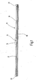
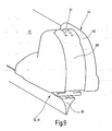
- a wiper device 10 comprises a wiper blade 12 which consists of a wiper strip 16 and a wiper lip 18 formed integrally therewith (cf. FIG. 1 ).
- the wiper lip 18 serves to clean a window of a motor vehicle.
- a coupling member 14 is mounted approximately centrally on the wiper blade 12 and serves for releasable connection with a pivotable wiper arm (not shown).
- the coupling part 14 has a hinge pin 15 whose longitudinal axis is aligned perpendicular to the longitudinal direction of the wiper blade 12.
- the wiper blade 12 has a cap 44 whose function is based on the FIGS. 7 to 13 is explained in more detail.
- the wiper blade 12 has a substantially symmetrical profile with a plurality of oppositely disposed guide grooves 24, 26, which are arranged in the wiper strip 16 below one of the wiper lip 18 opposite base portion 25 (see. FIG. 2 ).
- the provided below the base portion 25 first guide grooves 24 serve to receive two spring rails 20, which ensure the desired dimensional stability and Elastin activity of the wiper blade 12 when sweeping the disc.
- the spring rails 20 each consist of a flat, band-like element, which has an approximately rectangular cross-section - and that is largely elastically deformable only in the direction parallel to its narrow sides. Depending on the application, the spring rails 20 can already have a predetermined curvature in the relaxed state.
- the two spring rails 20 each protrude from the first guide groove 24 and are connected to each other at their ends by means of a connecting bridge 22 (see. FIG. 3 ).
- the distance between the two spring rails 20 is kept substantially constant over the entire length thereof by the two connecting bridges 22 welded at the ends.
- Spring rails 20 and connecting bridges 22 may, for example, consist of spring steel or of an elastic plastic, which preferably has a fiber reinforcement.
- the base portion 25 is located between each of the guide rails 20 and the connecting bridge 22, wherein a small distance for insertion of a flat fastening clips 30 (see. Figures 5 and 6 ) remains.
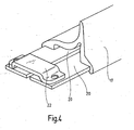
- first guide grooves 24 second guide grooves 26 can be seen, in which possibly a spoiler cover 17 can engage.
- this surrounds the wiper strip 16 only indirectly and is hooked in the laterally protruding from the first guide grooves 24 sections of the spring rails 20 (see. Figures 2 . 4 and 6 ), so that it remains at a separation of the wiper strip 16 of the spring rails 20 at this.
- the spoiler cover 17 is optional and can optionally be omitted.
- the mounting clip 30 may be attached to one end of the wiper strip 16 as shown in FIG FIG. 5 is clarified.
- the disk-shaped, preferably made of sheet metal or plastic fastening clip 30 has two lateral tabs 36 which can be bent laterally around the base portion 25 around.
- a spiked hook 32 can be seen on a region pointing towards the end of the wiper strip 16 which, when the fastening clip 30 is pressed in, penetrates vertically into the upper side 23 of the base section 25 and remains there.
- the pointed hook 32 has two barbs 34 which can get caught in the rubber of the wiper strip 16.
- two short, vertically upwardly facing stop hooks 40 can be seen, which can provide in conjunction with a, arranged in a central region of the mounting clip 30 spring tongue 42 for releasable connection with one of the connecting bridges 22.
- At one end of the hook 32 and the stop hook 40 opposite end of the clip 30 is shaped like a spade 38. This contour of the clip 30 facilitates the mounting of the wiper strip 16 by facilitating the insertion of the fastening clip 30 under the connecting bridge 22.
- FIG. 6 illustrates a locked position of the mounting clip 30, the stop hooks 40 abut against a front edge of the connecting bridge 22 and the relaxed spring tongue 42 abuts against the opposite edge of the connecting bridge 22.
- the wiper strip 16 provided with the fastening clip 30 is thus firmly connected to the two spring rails 20.
- the spring tongue 42 is pressed down on the top 23 of the base portion 25. In this position, the wiper strip 16 and the mounting clip 30 to the left (corresponding to FIG. 6 ) are pulled out under the connecting bridge 22.
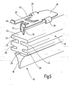
- the invention provides an actuator in the form of a cap 44 for easier release of the clip 30 before.
- the cap 44 has two slide rails 50, which engage in the first or second guide grooves 24, 26 and can engage around the spring rails 20.
- a hood 48 of the cap 44 is preferably adapted to the contour of the spoiler cover 17.
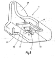
- a first variant of the cap 44 according to the FIGS. 7 and 8th has an elastically deformable locking cam 46 which is located at completely pushed onto the end of the wiper strip 16 cap 44 behind the spring tongue 42 and exerts no force on this.
- the cap 44 is in this case pushed with a stop pin 52 against the wiper strip 16 and the connecting bridge 22.
- the locking cam 46 is suspended elastically by means of a leaf spring and protrudes downward from a cover plate 58, which can form a further stop for the cap 44 by resting on the connecting bridge 22.
- the locking cam 46 has a rear ramp 54 with a ramp angle 56 of, for example, about 75 degrees. Such a ramp angle 56 ensures that the locking cam 46 can slide over the connecting bridge 22 and 44 is not blocked there when removing the cap.
- the spring tongue 42 is actuated by the locking cam 46 pressing thereon, so that the wiper strip 16 can be separated by the spring clip 20 with the fixing clip 30 fixed thereto by a longitudinal displacement.
- the spring stiffness of the spring tongue 42 must be less than that of the suspension of the locking cam 46, so that it is not pushed up before the spring tongue 42 has been pressed below the level of the connecting bridge 22. This mechanism allows for easy separation of a wiper strip 16 with spent wiper lip 18 from the reusable spring rails 20, without having to replace the entire wiper blade 12.
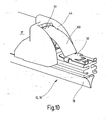
- FIGS. 9 to 13 An alternative embodiment of an unlocking device arranged in the cap 44 is in the FIGS. 9 to 13 illustrated.
- the cap 44 has a pivotally mounted securing bracket 60, which can be adapted in its contour of the curved surface of the cap and pivoted in an elongated recess 59 by a limited angle of about 25 degrees.
- a gripping surface 61 in the upper region of the securing bracket 60 By pressing on a gripping surface 61 in the upper region of the securing bracket 60, the latter can be moved from a locked position (FIG. FIG. 9 ) in an unlocked position ( Figures 10 and 11 ) to be brought.
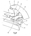
- the securing bracket 60 laterally has two pivot bearings 62 which are mounted on pivot axes 68 (cf. Figures 12 and 13 ) of the cap 44 are rotatably mounted.
- each locking recesses 71 are provided, engage in the corresponding locking projections 72 of the cap 44 and provide a latching of the securing bracket 60 in its normal position.
- An abutment step 66 at the lower end of Entriegelungsbügels 64 finds a stop on the connecting bridge 22, whereby the pivot angle of the securing bracket 60 is limited (see. FIG. 11 ).
- FIG. 10 shows the mounting clip 30 dipping under the cap after it has been unlocked by operation of the bracket 60.
- the cap 44 remains firmly connected in this alternative variant with the spring rails 20 and the spoiler cover 17.
- An ironing stop 70 on the one hand forms a support for the locked bracket 60 and at the same time constitutes a stop for the cap 44, since the ironing stop 70 bears against the edge of the connecting bridge 22 lying opposite the locking cam 46.
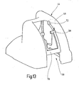
- FIG. 13 illustrates again the second variant of the cap 44 without the arranged in the recess 59 securing bracket 60th
- the illustrated caps 44 may be selectively attached to both ends of the wiper blade 12, but only one of the caps has the functions described.
- the other cap serves only for covering and optical covering of the connecting bridge having an end of the wiper blade.
Landscapes
- Engineering & Computer Science (AREA)
- Mechanical Engineering (AREA)
- Connection Of Plates (AREA)
- Insertion Pins And Rivets (AREA)
Abstract
Description
Die Erfindung betrifft eine Wischvorrichtung für Scheiben von Kraftfahrzeugen mit den im Oberbegriff des Patentanspruchs 1 genannten Merkmalen.The invention relates to a wiper device for windows of motor vehicles with the features mentioned in the preamble of
Gelenkfreie Wischblätter für Scheiben von Kraftfahrzeugen sind bekannt. Ein solches Wischblatt besteht typischerweise aus einer Wischleiste, die mittels einer oder zwei Federschiene versteift ist und die eine an der Scheibe anlegbare Wischlippe aufweist. Die Krümmung und die Federeigenschaften der die Wischleiste verstärkenden Federschienen bestimmen maßgeblich die Anpassungsfähigkeit der Wischlippe an die Krümmung der Windschutzscheibe und damit die Wischeigenschaften des Wischblattes. Das Wischblatt ist ungefähr mittig mittels eines Adapters bzw. eines Kupplungsteils lösbar an einem schwenkbaren Wischerarm des Kraftfahrzeugs fixiert.Articulated wiper blades for windows of motor vehicles are known. Such a wiper blade typically consists of a wiper strip which is stiffened by means of one or two spring rails and which has a wiper lip which can be applied to the window. The curvature and the spring properties of the wiper strip reinforcing spring rails significantly determine the adaptability of the wiper lip to the curvature of the windshield and thus the wiping properties of the wiper blade. The wiper blade is fixed approximately centrally by means of an adapter or a coupling part releasably attached to a pivotable wiper arm of the motor vehicle.
Bei einer bekannten Variante eines solchen einteiligen gelenkfreien Wischblattes ist eine Wischleiste mit zwei seitlich angebrachten Federschienen versehen, die an ihren beiden Enden jeweils mittels Querstegen einstückig miteinander verbunden sind. Derartige einteilige Wischblätter sind beispielsweise in der
Aus der
Eine Wischvorrichtung für Scheiben von Kraftfahrzeugen gemäß der vorliegenden Erfindung besteht aus einem gelenklosen Wischblatt mit einer Wischleiste, einer daran angeordneten Wischlippe und einem mit dem Wischblatt verbindbaren Kupplungsteil zur lösbaren Verbindung mit einem schwenkbaren Wischerarm des Fahrzeugs. Die Wischleiste weist ein Profil mit Führungsnuten zur seitlichen Aufnahme von zwei Federschienen auf,
die an ihren beiden Enden jeweils miteinander verbunden sind. Die Erfindung sieht vor, dass die Wischleiste eine Verriegelungseinrichtung aufweist, die in einer verriegelten Stellung die Federschienen in der Wischleiste fixiert, und die in einer entriegelten Stellung eine Längsverschiebung der Federschienen in den Führungsnuten der Wischleiste ermöglicht.A wiper device for windows of motor vehicles according to the present invention consists of a jointless wiper blade with a wiper strip, a wiper lip arranged thereon and a coupling part connectable to the wiper blade for detachable connection to a pivotable wiper arm of the vehicle. The wiper strip has a profile with guide grooves for laterally receiving two spring rails,
which are connected to each other at their two ends. The invention provides that the wiper strip has a locking device which fixes the spring rails in the wiper strip in a locked position, and which allows in an unlocked position a longitudinal displacement of the spring rails in the guide grooves of the wiper strip.
Durch eine Betätigung der Verriegelungseinrichtung kann somit das Wischblatt aus Gummi oder einem anderen geeigneten flexiblen Material von den Federschienen getrennt werden und bei Verschleiß separat ausgetauscht werden. Bei herkömmlichen gelenkfreien Wischblättern ist hingegen eine solche Trennung nicht möglich, da die Federschienen fest mit dem Wischblatt verbunden sind und nicht zerstörungsfrei hiervon getrennt werden kön- - nen. Dem gegenüber ermöglicht die Erfindung einen ressourcenschonenden Austausch nur der verbrauchten Komponenten der Wischvorrichtung.By actuating the locking device thus the wiper blade made of rubber or other suitable flexible material can be separated from the spring rails and replaced separately when worn. In contrast, in conventional joint-free wiper blades, such a separation is not possible, since the spring rails are firmly connected to the wiper blade and can not be separated from it non-destructively. In contrast, the invention allows a resource-saving replacement of only the used components of the wiper device.
Die Erfindung sieht vor, dass die Verriegelungseinrichtung einen auf einer Oberseite der Wischleiste fixierbaren Befestigungsclip umfasst, der in lösbarer Rastverbindung mit einer die Federschienen verbindenden Verbindungsbrücke zusammen wirkt. Außerden ist der Befestigungsclip mittels in die Führungsnuten eingreifender Laschen und wenigstens eines in die Oberseite eines Basisabschnitts der Wischleiste eindrückbaren Spitzhakens mit der Basisleiste verbindbar. Somit kann der flache Befestigungsclip im verriegelten Zustand die Verbindungsbrücke teilweise untergreifen, wobei er mittels Anschlaghaken und einer Federzunge gegen die Verbindungsbrücke verriegelt ist. Vorzugsweise ist die Verriegelung durch Drücken der elastisch verformbaren Federzunge gegen die Oberseite des Basisabschnitts der Wischleiste lösbar.The invention provides that the locking device comprises a fixable on an upper side of the wiper strip fastening clip, which acts in releasable latching connection with a connecting bridge connecting the spring rails together. Moreover, the fastening clip can be connected to the base strip by means of tabs engaging in the guide grooves and at least one hook which can be pressed into the upper side of a base section of the wiper strip. Thus, the flat mounting clip in the locked state, the connecting bridge partially engage, being locked by means of stop hooks and a spring tongue against the connecting bridge. Preferably, the lock can be released by pressing the elastically deformable spring tongue against the upper side of the base section of the wiper strip.
Wie bei den herkömmlichen gelenkfreien Wischblättern sind auch hier die Federschienen jeweils an ihren Enden einstückig miteinander verbunden, im vorliegenden Fall mittels einer Verbindungsbrücke. Auf diese Weise ist dafür gesorgt, dass die Federschienen nicht auseinander bewegt werden können und somit jederzeit seitlich fest im Profil der Wischleiste fixiert sind. Gemäß der vorliegenden Erfindung kann die Wischleiste jedoch in Längsrichtung gegen die Federschienen verschoben werden, wenn die Verriegelung des Befestigungsclips mit der Verbindungsbrücke gelöst wird.As in the conventional joint-free wiper blades, the spring rails are each connected in one piece at their ends here, in the present case by means of a connecting bridge. In this way, it is ensured that the spring rails can not be moved apart and are thus fixed at any time laterally fixed in the profile of the wiper strip. However, according to the present invention, the wiper strip can be longitudinally be moved against the spring rails when the locking of the mounting clip is released with the connecting bridge.
Die Verriegelung besteht aus Anschlaghaken des Befestigungsclips, die an einer Kante der Verbindungsbrücke anliegen. An deren gegenüber liegender Kante liegt im verriegelten Zustand die flexible Federzunge an, die durch Drücken nach unten auf die Wischleiste von der Kante weg geschoben werden kann. Hierdurch kann der Befestigungsclip bei einer Längsverschiebung der Wischleiste gegen die Federschienen unter der Verbindungsbrücke hindurch tauchen und die Wischleiste kann in einer Verschiebebewegung in Längsrichtung vollständig von den Federschienen getrennt werden. Hierbei gleiten diese in einer ersten Führungsnut zu beiden Seiten der Wischleiste.The lock consists of stop hooks of the mounting clip, which rest against one edge of the connecting bridge. At its opposite edge is in the locked state, the flexible spring tongue, which can be pushed by pressing down on the wiper strip from the edge away. As a result, the fastening clip can dip under a longitudinal displacement of the wiper strip against the spring rails under the connecting bridge and the wiper strip can be completely separated in a sliding movement in the longitudinal direction of the spring rails. These slide in a first guide groove on both sides of the wiper strip.
Eine Ausführungsform der Erfindung sieht vor, dass die Verriegelung durch Betätigung eines Sicherungsbügels lösbar ist, der in einer am Ende des Wischblattes befindlichen Kappe gelagert ist. Die Kappe weist einen mit der Federzunge zusammen wirkenden, elastisch verformbaren Rastnocken auf, der beim Abziehen der Kappe die Federzunge betätigt. Der Rastnocken sorgt zudem dafür, dass die Kappe sich nur-durch einen gewissen Kraftaufwand abziehen lässt und nicht während des normalen Betriebs der Wischvorrichtung verloren gehen kann. Falls die Kappe dennoch verloren geht, wird die Verriegelung dadurch nicht automatisch gelöst, sondern kann ggf. manuell gelöst werden.An embodiment of the invention provides that the lock is releasable by actuation of a securing bracket, which is mounted in a cap located at the end of the wiper blade. The cap has a cooperating with the spring tongue, elastically deformable locking cams, which actuates the spring tongue when removing the cap. The locking cam also ensures that the cap can only be deducted by a certain amount of force and can not be lost during normal operation of the wiper device. If the cap is still lost, the lock is not solved automatically, but can be solved manually if necessary.
Die Betätigung der Verriegelungseinrichtung erfolgt bei dieser Ausführungsform durch Entfernen der Kappe vom Wischblatt.The actuation of the locking device takes place in this embodiment by removing the cap from the wiper blade.
Eine alternative Ausführungsform sieht vor, dass die Verriegelung durch Betätigung eines Sicherungsbügels lösbar ist, der in einer am Ende des Wischblattes befindlichen Kappe gelagert ist. Die Kappe weist hierbei eine leicht veränderte Gestalt und Funktion auf und verbleibt auch bei der Entriegelung am Wischblatt. Zu diesem Zweck ist die Kappe mittels wenigstens eines im Wesentlichen starren Rastnockens an der Verbindungsbrücke fixiert. Die Federzunge ist bei dieser erfindungsgemäßen Ausführungsform beim Verschwenken des Sicherungsbügels durch einen an diesem befmdlichen Entriegelungsbügel betätigbar. Somit ist eine definierte Entriegelung des Befestigungsclips möglich.An alternative embodiment provides that the lock is releasable by actuation of a securing bracket, which is mounted in a cap located at the end of the wiper blade. The cap in this case has a slightly different shape and function and remains even when unlocking the wiper blade. For this purpose, the cap is fixed by means of at least one substantially rigid latching cam on the connecting bridge. The spring tongue is in this embodiment of the invention during pivoting of the securing bracket by a befmdlichen on this unlocking bracket operable. Thus, a defined unlocking of the mounting clip is possible.
Beide alternativen Ausführungsformen können weiterhin vorsehen, dass die Kappe zwei Gleitschienen aufweist, die jeweils in die Führungsnuten der Wischleiste eingreifen. Zur Sicherstellung der erwähnten Funktion ist lediglich eine Verriegelungseinrichtung sowie eine Kappe an einem Ende des Wischblattes erforderlich. Aus optischen Gründen kann jedoch zusätzlich am anderen Ende des Wischblattes eine gleichartige Kappe angebracht sein, die jedoch ohne Funktion ist.Both alternative embodiments may further provide that the cap has two slide rails, which engage respectively in the guide grooves of the wiper strip. To ensure the mentioned function, only a locking device and a cap at one end of the wiper blade is required. For optical reasons, however, may be additionally attached to the other end of the wiper blade a similar cap, which is without function.
Weitere vorteilhafte Ausgestaltungen der Erfindung ergeben sich aus den übrigen, in den abhängigen Ansprüchen genannten Merkmalen.Further advantageous embodiments of the invention will become apparent from the remaining features mentioned in the dependent claims.
Die Erfindung wird nachfolgend in bevorzugten Ausführungsbeispielen anhand der zugehörigen Zeichnungen näher erläutert. Dabei zeigt:
Figur 1- eine schematische Seitenansicht einer erfindungsgemäßen Wischvorrichtung,
- Figur 2
- eine schematische Draufsicht auf die Wischvorrichtung ge- mäß
Figur 1 - Figur 3
- eine perspektivische Detailansicht zweier miteinander ver- bundener Federschienen der Wischvorrichtung,
- Figur 4
- eine weitere perspektivische Ansicht der mittels einer Ver- bindungsbrücke verbundenen Federschienen,
- Figur 5
- eine perspektivische Detailansicht eines Wischblattes und eines damit verbindbaren Befestigungsclips der Wischvor- richtung,
- Figur 6
- eine perspektivische Detailansicht der mit dem Wischblatt verbundenen Federschienen,
- Figur 7
- eine erste Variante einer über ein Ende des Wischblattes schiebbaren Kappe in perspektivischer Darstellung,
- Figur 8
- eine weitere perspektivische Ansicht der Kappe gemäß Fi- gur 7,
- Figur 9
- eine alternative Variante einer über das Wischblatt gescho- benen Kappe,
Figur 10- eine perspektivische Teilansicht einer von den Federschie- nen entriegelten Wischleiste,
- Figur 11
- eine perspektivische Detailansicht des Zusammenwirkens eines Sicherungsbügels mit dem Befestigungsclip,
Figur 12- eine perspektivische Ansicht der Kappe gemäß
Figur 9 und - Figur 13
- eine weitere perspektivische Ansicht der Kappe gemäß Fi- gur 9 mit entferntem Sicherungsbügel.
- FIG. 1
- a schematic side view of a wiper device according to the invention,
- FIG. 2
- a schematic plan view of the wiper according to GE
FIG. 1 . - FIG. 3
- 2 shows a perspective detail view of two spring rails of the wiper device connected to one another,
- FIG. 4
- 2 shows another perspective view of the spring bars connected by means of a connection bridge,
- FIG. 5
- 2 shows a perspective detail view of a wiper blade and a fastening clip of the wiping device that can be connected thereto;
- FIG. 6
- a detailed perspective view of the spring rails connected to the wiper blade,
- FIG. 7
- a first variant of a sliding over one end of the wiper blade cap in perspective view,
- FIG. 8
- another perspective view of the cap according to Figure 7,
- FIG. 9
- an alternative variant of a cap pushed over the wiper blade,
- FIG. 10
- 1 is a partial perspective view of a wiper strip unlocked by the spring rails;
- FIG. 11
- a detailed perspective view of the interaction of a securing bracket with the mounting clip,
- FIG. 12
- a perspective view of the cap according to
FIG. 9 and - FIG. 13
- another perspective view of the cap according to Figure 9 with removed securing bracket.
Eine erfindungsgemäße Wischvorrichtung 10 umfasst ein Wischblatt 12, das aus einer Wischleiste 16 und einer einstückig mit dieser ausgebildeten Wischlippe 18 besteht (vgl.
Das Wischblatt 12 weist ein weitgehend symmetrisches Profil mit mehreren, gegenüber liegend angeordneten Führungsnuten 24, 26 auf, die in der Wischleiste 16 unterhalb eines der Wischlippe 18 gegenüber liegenden Basisabschnitts 25 angeordnet sind (vgl.
Die beiden Federschienen 20 ragen jeweils aus der ersten Führungsnut 24 und sind an ihren Enden jeweils mittels einer Verbindungsbrücke 22 miteinander verbunden (vgl.
Der Basisabschnitt 25 befindet sich jeweils zwischen den Führungsschienen 20 und der Verbindungsbrücke 22, wobei ein geringer Abstand zum Einschieben eines flachen Befestigungsclips 30 (vgl.
Unterhalb der ersten Führungsnuten 24 sind zweite Führungsnuten 26 erkennbar, in die ggf. eine Spoilerabdeckung 17 eingreifen kann. Im gezeigten Ausführungsbeispiel der
Am unteren Ende der Wischleiste 16, unterhalb der zweiten Führungsnuten 26, befindet sich ein mittiger Gelenkabschnitt 28, der eine flexible Verbindung zur Wischlippe 18 darstellt. Die Wischlippe 18 kann somit je nach Wischrichtung des Wischblatts 12 eine eingeschränkte Kippbewegung ausführen.At the lower end of the
Der Befestigungsclip 30 kann an einem Ende der Wischleiste 16 angebracht werden, wie dies in
Da die Federzunge 42 relativ schwer zugänglich ist und nur unter Zuhilfenahme von Werkzeug nach unten gedrückt werden kann, sieht die Erfindung eine Betätigungseinrichtung in Gestalt einer Kappe 44 zur leichteren Entriegelung des Clips 30 vor. Die Kappe 44 weist zwei Gleitschienen 50 auf, die in die ersten oder zweiten Führungsnuten 24, 26 eingreifen bzw. die Federschienen 20 umgreifen können. Eine Haube 48 der Kappe 44 ist vorzugsweise der Kontur der Spoilerabdeckung 17 angepasst. Eine erste Variante der Kappe 44 gemäß den
Der Rastnocken 46 weist rückseitig eine Rampe 54 mit einem Rampenwinkel 56 von bspw. ca. 75 Grad auf. Ein solcher Rampenwinkel 56 sorgt dafür, dass der Rastnocken 46 über die Verbindungsbrücke 22 gleiten kann und beim Abziehen der Kappe 44 nicht dort blockiert wird. Beim Abziehen der Kappe 44 wird die Federzunge 42 durch den darauf drückenden Rastnocken 46 betätigt, so dass die Wischleiste 16 mit dem darauf fixierten Befestigungsclip 30 durch eine Längsverschiebung von den Federschienen 20 getrennt werden kann. Die Federsteifigkeit der Federzunge 42 muss hierbei geringer sein als die der Aufhängung des Rastnockens 46, damit dieser nicht nach oben gedrückt wird, bevor die Federzunge 42 unter das Niveau der Verbindungsbrücke 22 gedrückt worden ist. Dieser Mechanismus ermöglicht eine einfache Trennung einer Wischleiste 16 mit verbrauchter Wischlippe 18 von den wieder verwendbaren Federschienen 20, ohne dass das gesamte Wischblatt 12 ausgetauscht werden muss.The locking
Eine alternative Ausgestaltung einer in der Kappe 44 angeordneten Entriegelungseinrichtung ist in den
Unterhalb der Grifffläche 61 weist der Sicherungsbügel 60 seitlich zwei Schwenklager 62 auf, die auf Schwenkachsen 68 (vgl.
Die gezeigten Kappen 44 können wahlweise an beiden Enden des Wischblattes 12 angebracht sein, wobei jedoch nur eine der Kappen die beschriebenen Funktionen aufweist. Die andere Kappe dient lediglich zur Abdeckung und optischen Verkleidung des eine Verbindungsbrücke aufweisenden Endes des Wischblattes.The illustrated caps 44 may be selectively attached to both ends of the
Claims (9)
- Wiping device for windows of motor vehicles, consisting of a hingeless wiper blade with a wiper strip, a wiper lip arranged thereon and a coupling part which can be connected to the wiper blade and is intended for the releasable connection to a pivotable wiper arm of the vehicle, wherein the wiper strip comprises a profile with guide grooves for laterally receiving two spring rails which are connected to each other in each case at both ends thereof, wherein the wiper strip (16) has a locking device which, in a locked position, fixes the spring rails (20) in the wiper strip (16) and which, in an unlocked position, permits longitudinal displacement of the spring rails (20) in the guide grooves (24) of the wiper strip (16), and the locking device comprises a fastening clip (30) which is fixable on the upper side (23) of the wiper strip (16) and, in a releasable latching connection, interacts with a connecting bridge (22) connecting the spring rails (20), characterized in that the fastening clip (30) can be connected to the wiper strip (16) by means of tabs (36) engaging in the guide grooves (24) of the wiper strip (16) and by means of at least one pointed hook (32) which can be pressed into the upper side (23) of a base section (25).
- Wiping device according to Claim 1, characterized in that, in the locked position, the fastening clip (30) partially engages under the connecting bridge (22) and is locked against the connecting bridge (22) by means of stop hooks (40) and a spring tongue (42).
- Wiping device according to Claim 2, characterized in that the locking can be released by pressing the elastically deformable spring tongue (42) against the upper side (23) of the base section (25) of the wiper strip (16).
- Wiping device according to Claim 3, characterized in that the locking can be released by removing a cap (44) from the end of the wiper blade (12).
- Wiping device according to Claim 3 or 4, characterized in that the cap (44) has an elastically deformable latching cam (46) which interacts with the spring tongue (42) and, when the cap (44) is pulled off, actuates the spring tongue (42).
- Wiping device according to Claim 3, characterized in that the locking can be released by actuating a securing bow (60) which is mounted in a cap (44) located at the end of the wiper blade (12).
- Wiping device according to Claim 6, characterized in that the spring tongue (42) can be actuated during pivoting of the securing bow (60) by means of an unlocking bow (64) located on the latter.
- Wiping device according to Claim 6 or 7, characterized in that the cap (44) is fixed on the connecting bridge (22) by means of at least one substantially rigid latching cam (46).
- Wiping device according to one of Claims 4 to 8, characterized in that the cap (44) has two sliding rails (50) each engaging in the guide grooves (24) of the wiper strip (16).
Applications Claiming Priority (3)
| Application Number | Priority Date | Filing Date | Title |
|---|---|---|---|
| DE10259478A DE10259478A1 (en) | 2002-12-19 | 2002-12-19 | Wiper device for windows of motor vehicles |
| DE10259478 | 2002-12-19 | ||
| PCT/DE2003/003276 WO2004056623A1 (en) | 2002-12-19 | 2003-10-02 | Wiping device for windows of motor vehicles |
Publications (2)
| Publication Number | Publication Date |
|---|---|
| EP1585657A1 EP1585657A1 (en) | 2005-10-19 |
| EP1585657B1 true EP1585657B1 (en) | 2011-03-02 |
Family
ID=32403950
Family Applications (1)
| Application Number | Title | Priority Date | Filing Date |
|---|---|---|---|
| EP03773482A Expired - Lifetime EP1585657B1 (en) | 2002-12-19 | 2003-10-02 | Wiping device for windows of motor vehicles |
Country Status (5)
| Country | Link |
|---|---|
| US (1) | US7581280B2 (en) |
| EP (1) | EP1585657B1 (en) |
| JP (1) | JP4732759B2 (en) |
| DE (2) | DE10259478A1 (en) |
| WO (1) | WO2004056623A1 (en) |
Families Citing this family (46)
| Publication number | Priority date | Publication date | Assignee | Title |
|---|---|---|---|---|
| DE102004015423A1 (en) * | 2004-03-26 | 2005-10-13 | Robert Bosch Gmbh | wiper blade |
| DE102004051467A1 (en) * | 2004-05-28 | 2005-12-15 | Robert Bosch Gmbh | wiper blade |
| CA2514372A1 (en) * | 2004-07-30 | 2006-01-30 | M Management-Tex, Ltd. | Windshield wiper structure |
| KR100633643B1 (en) * | 2004-11-24 | 2006-10-11 | 현대자동차주식회사 | End clip of wiper blade for automobile |
| ES2303182T3 (en) * | 2005-01-25 | 2008-08-01 | Federal-Mogul S.A. | WINDSHIELD CLEANING DEVICE. |
| ES2314561T3 (en) * | 2005-03-02 | 2009-03-16 | Federal-Mogul S.A. | WINDSHIELD CLEANING DEVICE. |
| DE102005052258A1 (en) | 2005-11-02 | 2007-05-03 | Robert Bosch Gmbh | Wiper blade for motor vehicle, has spring rails whose ends are connected with each other by strap, where holes are plastically deformed in sides of rails in such a manner that strap is firmly connected with spring rails |
| EP1829758A1 (en) * | 2006-03-03 | 2007-09-05 | Chin-Lien Lin | Windshield wiper assembly |
| EP2054276B1 (en) * | 2006-08-18 | 2017-07-12 | Robert Bosch GmbH | Wiper blade with a supporting element |
| DE102006059077A1 (en) * | 2006-12-14 | 2008-06-19 | Robert Bosch Gmbh | wiper blade |
| US7992248B2 (en) † | 2007-05-22 | 2011-08-09 | Federal-Mogul Corporation | Spoilerless flat wiper blade assembly |
| DE102007043528A1 (en) | 2007-09-12 | 2009-03-19 | Robert Bosch Gmbh | wiper blade |
| FR2922502B1 (en) * | 2007-10-22 | 2010-04-02 | Valeo Systemes Dessuyage | END TIP FOR WIPER BLADE |
| DE102008000708A1 (en) * | 2008-03-17 | 2009-09-24 | Robert Bosch Gmbh | wiper blade |
| KR101098004B1 (en) | 2009-08-26 | 2011-12-22 | 주식회사 캐프 | Multi-adapter of vehicle wiper |
| DE102010042095A1 (en) * | 2009-10-09 | 2011-04-14 | Robert Bosch Gmbh | wiper blade |
| US20130227809A1 (en) | 2012-02-24 | 2013-09-05 | Pylon Manufacturing Corp. | Wiper blade |
| US8495787B2 (en) | 2010-08-03 | 2013-07-30 | Rally Manufacturing, Inc. | Windshield wiper |
| FR2964618B1 (en) * | 2010-09-09 | 2012-10-12 | Valeo Systemes Dessuyage | DEVICE FOR SOLIDARIZING A LAMP ON A WIPING BROOM |
| USD706200S1 (en) | 2010-09-22 | 2014-06-03 | Pylon Manufacturing Corporation | Windshield wiper cover |
| CN103328279B (en) * | 2010-12-27 | 2015-09-16 | 株式会社美姿把 | Rain shaving blade and assemble the method for this rain shaving blade |
| FR2973312B1 (en) * | 2011-03-31 | 2013-05-03 | Valeo Systemes Dessuyage | END TIP FOR TUMBLING BRUSH |
| US9457768B2 (en) | 2011-04-21 | 2016-10-04 | Pylon Manufacturing Corp. | Vortex damping wiper blade |
| US9174609B2 (en) | 2011-04-21 | 2015-11-03 | Pylon Manufacturing Corp. | Wiper blade with cover |
| DE102011078163A1 (en) * | 2011-06-28 | 2013-01-03 | Robert Bosch Gmbh | Wiper blade device |
| MX345011B (en) | 2011-07-28 | 2017-01-11 | Pylon Mfg Corp | Windshield wiper adapter, connector and assembly. |
| MX347284B (en) | 2011-07-29 | 2017-04-21 | Pylon Mfg Corp | Windshield wiper connector. |
| US9108595B2 (en) | 2011-07-29 | 2015-08-18 | Pylon Manufacturing Corporation | Windshield wiper connector |
| US8806700B2 (en) | 2011-07-29 | 2014-08-19 | Pylon Manufacturing Corporation | Wiper blade connector |
| US20130219649A1 (en) | 2012-02-24 | 2013-08-29 | Pylon Manufacturing Corp. | Wiper blade |
| US10829092B2 (en) | 2012-09-24 | 2020-11-10 | Pylon Manufacturing Corp. | Wiper blade with modular mounting base |
| US10166951B2 (en) | 2013-03-15 | 2019-01-01 | Pylon Manufacturing Corp. | Windshield wiper connector |
| KR101474838B1 (en) | 2013-07-01 | 2014-12-22 | 주식회사 캐프 | A Wiper Blade Assembly |
| US9505380B2 (en) | 2014-03-07 | 2016-11-29 | Pylon Manufacturing Corp. | Windshield wiper connector and assembly |
| USD787308S1 (en) | 2014-10-03 | 2017-05-23 | Pylon Manufacturing Corp. | Wiper blade package |
| USD777079S1 (en) | 2014-10-03 | 2017-01-24 | Pylon Manufacturing Corp. | Wiper blade frame |
| WO2017075066A1 (en) | 2015-10-26 | 2017-05-04 | Pylon Manufacturing Corp. | Wiper blade |
| US11040705B2 (en) | 2016-05-19 | 2021-06-22 | Pylon Manufacturing Corp. | Windshield wiper connector |
| CN109311452A (en) | 2016-05-19 | 2019-02-05 | 电缆塔制造有限公司 | Windscreen wiper connector |
| WO2017201485A1 (en) | 2016-05-19 | 2017-11-23 | Pylon Manufacturing Corp. | Windshield wiper connector |
| WO2017201473A1 (en) | 2016-05-19 | 2017-11-23 | Pylon Manufacturing Corp. | Windshield wiper blade |
| AU2017268008A1 (en) | 2016-05-19 | 2018-11-22 | Pylon Manufacturing Corp. | Windshield wiper connector |
| WO2018081791A1 (en) | 2016-10-31 | 2018-05-03 | Pylon Manufacturing Corp. | Wiper blade with cover |
| CN109795452B (en) * | 2019-03-25 | 2020-08-11 | 厦门富可汽车配件有限公司 | Windshield wiper adhesive tape anti-disengaging structure and windshield wiper thereof |
| KR200494732Y1 (en) * | 2020-07-31 | 2021-12-09 | 점 수 연 | A fixed device of car window brush |
| CN115743035A (en) * | 2022-10-28 | 2023-03-07 | 江苏云睿汽车电器系统有限公司 | Anti-shake boneless wiper |
Citations (1)
| Publication number | Priority date | Publication date | Assignee | Title |
|---|---|---|---|---|
| US5493750A (en) * | 1992-02-04 | 1996-02-27 | Robert Bosch Gmbh | Blade assembly for wiping motor vehicle windscreens |
Family Cites Families (16)
| Publication number | Priority date | Publication date | Assignee | Title |
|---|---|---|---|---|
| US3116507A (en) * | 1960-05-02 | 1964-01-07 | Trico Products Corp | Windshield wiper system |
| US3626544A (en) | 1970-09-16 | 1971-12-14 | Roberk Co The | Clip for windshield wiper blade refill |
| US4075731A (en) * | 1975-10-28 | 1978-02-28 | The Anderson Company | Windshield wiper refill unit |
| JPS5853548A (en) * | 1981-09-22 | 1983-03-30 | Ichikoh Ind Ltd | Assembling method of wiper blade |
| NL8600342A (en) | 1986-02-12 | 1987-09-01 | Philips Nv | ORGANIZED BY CONTENT ADDRESSABLE MEMORY. |
| JPH0195461U (en) * | 1987-12-18 | 1989-06-23 | ||
| IT1241627B (en) | 1990-12-07 | 1994-01-25 | Champion Spark Plug Divisione | WIPER ARM FOR VEHICLE WIPER DEVICES |
| JPH06229331A (en) | 1993-01-30 | 1994-08-16 | Suzuki Motor Corp | Fuel passage control device of internal combustion engine |
| DE29611722U1 (en) | 1996-07-05 | 1997-11-06 | Robert Bosch Gmbh, 70469 Stuttgart | Wiper blade for windows of motor vehicles |
| JP2995613B2 (en) * | 1996-07-11 | 1999-12-27 | マルエヌ株式会社 | Fixtures to be placed at both ends of the rubber ribbon with the ribbon holder attached to the rubber ribbon holding claw of the stay that constitutes the wiper blade |
| US5933910A (en) * | 1997-09-24 | 1999-08-10 | Acd Tridon Inc. | Retainer clip for windshield wiper refill |
| JP2000071944A (en) | 1998-08-31 | 2000-03-07 | Asmo Co Ltd | Wiper blade |
| DE19951363A1 (en) * | 1999-10-26 | 2001-05-03 | Bosch Gmbh Robert | Wiper blade for windows of motor vehicles |
| DE10025710A1 (en) * | 2000-02-23 | 2001-08-30 | Bosch Gmbh Robert | Wiper blade for windows, in particular of motor vehicles |
| DE10025706A1 (en) * | 2000-05-25 | 2001-11-29 | Bosch Gmbh Robert | Wiper blade for cleaning vehicle windows |
| DE10054235A1 (en) | 2000-11-02 | 2002-05-08 | Valeo Auto Electric Gmbh | wiper device |
-
2002
- 2002-12-19 DE DE10259478A patent/DE10259478A1/en not_active Withdrawn
-
2003
- 2003-10-02 US US10/538,948 patent/US7581280B2/en active Active
- 2003-10-02 DE DE50313517T patent/DE50313517D1/en not_active Expired - Lifetime
- 2003-10-02 EP EP03773482A patent/EP1585657B1/en not_active Expired - Lifetime
- 2003-10-02 WO PCT/DE2003/003276 patent/WO2004056623A1/en active Application Filing
- 2003-10-02 JP JP2004561014A patent/JP4732759B2/en not_active Expired - Lifetime
Patent Citations (1)
| Publication number | Priority date | Publication date | Assignee | Title |
|---|---|---|---|---|
| US5493750A (en) * | 1992-02-04 | 1996-02-27 | Robert Bosch Gmbh | Blade assembly for wiping motor vehicle windscreens |
Also Published As
| Publication number | Publication date |
|---|---|
| DE10259478A1 (en) | 2004-07-01 |
| JP4732759B2 (en) | 2011-07-27 |
| WO2004056623A1 (en) | 2004-07-08 |
| US7581280B2 (en) | 2009-09-01 |
| DE50313517D1 (en) | 2011-04-14 |
| US20060112511A1 (en) | 2006-06-01 |
| EP1585657A1 (en) | 2005-10-19 |
| JP2006510526A (en) | 2006-03-30 |
Similar Documents
| Publication | Publication Date | Title |
|---|---|---|
| EP1585657B1 (en) | Wiping device for windows of motor vehicles | |
| DE4439109B4 (en) | With a wind deflector completeable wiper blade | |
| EP1732792B1 (en) | Wiper blade | |
| EP1833707B1 (en) | Windscreen wiper system | |
| DE102007022185B4 (en) | Connecting element for articulating a wiper blade with a wiper arm | |
| EP1963148B1 (en) | Connection apparatus for a wiping arm | |
| EP2142404B1 (en) | Connector device | |
| EP1824717B1 (en) | Wiper blade | |
| EP1485280A1 (en) | Wiper device comprising a flat wiper blade and wiper arm | |
| WO2002051677A1 (en) | Wiper device, especially for windshields of automobiles | |
| DE4445414B4 (en) | Connector for a windshield wiper device of a motor vehicle | |
| DE102005048344A1 (en) | wiper arm | |
| WO2001094166A1 (en) | Windshield wiper for motor vehicles | |
| DE2839587A1 (en) | Windscreen wiper blade support - includes segmented plastics moulding to even pressure over blade | |
| DE10340139B4 (en) | articulation | |
| DE3619589C2 (en) | Wiper blade for window cleaning systems on vehicles, in particular on motor vehicles | |
| DE102008010564B4 (en) | Wiper blade for a vehicle | |
| EP1437273B1 (en) | Connector assembly of a wiper device for windshields of vehicles | |
| DE69003669T2 (en) | Windscreen wiper blade, which has great flexibility, in particular for strongly curved windows of a motor vehicle. | |
| DE19811702A1 (en) | Wiper blade for motor vehicle's windscreen clearing system | |
| EP1641664B1 (en) | Wiper arm for a windscreen wiper | |
| DE10029144A1 (en) | Windscreen wiper has an upper clip for mounting to the wiper arm and a lower clip holding the wiper blade with a joint between them with ratchet arms to lock the clips together | |
| EP2214936A1 (en) | Wiper blade | |
| DE10044884A1 (en) | Connector for mounting windscreen wiper blade on arm is attached to it by pins which fit into mounting on arm, base of connector having claws with longitudinal grooves which fit around edges of wiper blade mounting rail | |
| DE3026729A1 (en) | WIPER BLADE FOR MOTOR VEHICLES |
Legal Events
| Date | Code | Title | Description |
|---|---|---|---|
| PUAI | Public reference made under article 153(3) epc to a published international application that has entered the european phase |
Free format text: ORIGINAL CODE: 0009012 |
|
| 17P | Request for examination filed |
Effective date: 20050719 |
|
| AK | Designated contracting states |
Kind code of ref document: A1 Designated state(s): AT BE BG CH CY CZ DE DK EE ES FI FR GB GR HU IE IT LI LU MC NL PT RO SE SI SK TR |
|
| AX | Request for extension of the european patent |
Extension state: AL LT LV MK |
|
| DAX | Request for extension of the european patent (deleted) | ||
| RBV | Designated contracting states (corrected) |
Designated state(s): DE FR GB |
|
| 17Q | First examination report despatched |
Effective date: 20091202 |
|
| GRAP | Despatch of communication of intention to grant a patent |
Free format text: ORIGINAL CODE: EPIDOSNIGR1 |
|
| GRAS | Grant fee paid |
Free format text: ORIGINAL CODE: EPIDOSNIGR3 |
|
| GRAA | (expected) grant |
Free format text: ORIGINAL CODE: 0009210 |
|
| AK | Designated contracting states |
Kind code of ref document: B1 Designated state(s): DE FR GB |
|
| REG | Reference to a national code |
Ref country code: GB Ref legal event code: FG4D Free format text: NOT ENGLISH |
|
| REF | Corresponds to: |
Ref document number: 50313517 Country of ref document: DE Date of ref document: 20110414 Kind code of ref document: P |
|
| REG | Reference to a national code |
Ref country code: DE Ref legal event code: R096 Ref document number: 50313517 Country of ref document: DE Effective date: 20110414 |
|
| PLBE | No opposition filed within time limit |
Free format text: ORIGINAL CODE: 0009261 |
|
| STAA | Information on the status of an ep patent application or granted ep patent |
Free format text: STATUS: NO OPPOSITION FILED WITHIN TIME LIMIT |
|
| 26N | No opposition filed |
Effective date: 20111205 |
|
| REG | Reference to a national code |
Ref country code: DE Ref legal event code: R097 Ref document number: 50313517 Country of ref document: DE Effective date: 20111205 |
|
| REG | Reference to a national code |
Ref country code: FR Ref legal event code: PLFP Year of fee payment: 13 |
|
| REG | Reference to a national code |
Ref country code: FR Ref legal event code: PLFP Year of fee payment: 14 |
|
| REG | Reference to a national code |
Ref country code: FR Ref legal event code: PLFP Year of fee payment: 15 |
|
| REG | Reference to a national code |
Ref country code: FR Ref legal event code: PLFP Year of fee payment: 16 |
|
| PGFP | Annual fee paid to national office [announced via postgrant information from national office to epo] |
Ref country code: FR Payment date: 20221020 Year of fee payment: 20 |
|
| PGFP | Annual fee paid to national office [announced via postgrant information from national office to epo] |
Ref country code: GB Payment date: 20221024 Year of fee payment: 20 Ref country code: DE Payment date: 20221215 Year of fee payment: 20 |
|
| REG | Reference to a national code |
Ref country code: DE Ref legal event code: R071 Ref document number: 50313517 Country of ref document: DE |
|
| REG | Reference to a national code |
Ref country code: GB Ref legal event code: PE20 Expiry date: 20231001 |
|
| PG25 | Lapsed in a contracting state [announced via postgrant information from national office to epo] |
Ref country code: GB Free format text: LAPSE BECAUSE OF EXPIRATION OF PROTECTION Effective date: 20231001 |