EP1584503A2 - Système de suspension pour véhicule automobile - Google Patents
Système de suspension pour véhicule automobile Download PDFInfo
- Publication number
- EP1584503A2 EP1584503A2 EP05004468A EP05004468A EP1584503A2 EP 1584503 A2 EP1584503 A2 EP 1584503A2 EP 05004468 A EP05004468 A EP 05004468A EP 05004468 A EP05004468 A EP 05004468A EP 1584503 A2 EP1584503 A2 EP 1584503A2
- Authority
- EP
- European Patent Office
- Prior art keywords
- wheel side
- chambers
- absorbers
- absorber
- rear wheel
- Prior art date
- Legal status (The legal status is an assumption and is not a legal conclusion. Google has not performed a legal analysis and makes no representation as to the accuracy of the status listed.)
- Granted
Links
- 239000000725 suspension Substances 0.000 title claims description 42
- 239000006096 absorbing agent Substances 0.000 claims abstract description 309
- 238000013016 damping Methods 0.000 claims abstract description 78
- 238000005192 partition Methods 0.000 claims abstract description 40
- 230000008878 coupling Effects 0.000 claims abstract description 27
- 238000010168 coupling process Methods 0.000 claims abstract description 27
- 238000005859 coupling reaction Methods 0.000 claims abstract description 27
- 239000012530 fluid Substances 0.000 claims description 129
- 230000003247 decreasing effect Effects 0.000 claims description 13
- 230000035939 shock Effects 0.000 abstract description 83
- 238000004891 communication Methods 0.000 description 16
- 230000007423 decrease Effects 0.000 description 16
- 230000008859 change Effects 0.000 description 11
- 230000000694 effects Effects 0.000 description 10
- 230000002093 peripheral effect Effects 0.000 description 10
- 238000005096 rolling process Methods 0.000 description 10
- 230000006835 compression Effects 0.000 description 3
- 238000007906 compression Methods 0.000 description 3
- 238000002474 experimental method Methods 0.000 description 3
- 238000010586 diagram Methods 0.000 description 2
- 230000004044 response Effects 0.000 description 2
- 230000006872 improvement Effects 0.000 description 1
- 238000004519 manufacturing process Methods 0.000 description 1
- 230000007935 neutral effect Effects 0.000 description 1
Images


Classifications
-
- B—PERFORMING OPERATIONS; TRANSPORTING
- B60—VEHICLES IN GENERAL
- B60G—VEHICLE SUSPENSION ARRANGEMENTS
- B60G17/00—Resilient suspensions having means for adjusting the spring or vibration-damper characteristics, for regulating the distance between a supporting surface and a sprung part of vehicle or for locking suspension during use to meet varying vehicular or surface conditions, e.g. due to speed or load
- B60G17/02—Spring characteristics, e.g. mechanical springs and mechanical adjusting means
- B60G17/033—Spring characteristics, e.g. mechanical springs and mechanical adjusting means characterised by regulating means acting on more than one spring
-
- B—PERFORMING OPERATIONS; TRANSPORTING
- B60—VEHICLES IN GENERAL
- B60G—VEHICLE SUSPENSION ARRANGEMENTS
- B60G21/00—Interconnection systems for two or more resiliently-suspended wheels, e.g. for stabilising a vehicle body with respect to acceleration, deceleration or centrifugal forces
- B60G21/02—Interconnection systems for two or more resiliently-suspended wheels, e.g. for stabilising a vehicle body with respect to acceleration, deceleration or centrifugal forces permanently interconnected
- B60G21/06—Interconnection systems for two or more resiliently-suspended wheels, e.g. for stabilising a vehicle body with respect to acceleration, deceleration or centrifugal forces permanently interconnected fluid
-
- B—PERFORMING OPERATIONS; TRANSPORTING
- B60—VEHICLES IN GENERAL
- B60G—VEHICLE SUSPENSION ARRANGEMENTS
- B60G2204/00—Indexing codes related to suspensions per se or to auxiliary parts
- B60G2204/80—Interactive suspensions; arrangement affecting more than one suspension unit
- B60G2204/83—Type of interconnection
- B60G2204/8304—Type of interconnection using a fluid
-
- B—PERFORMING OPERATIONS; TRANSPORTING
- B60—VEHICLES IN GENERAL
- B60G—VEHICLE SUSPENSION ARRANGEMENTS
- B60G2204/00—Indexing codes related to suspensions per se or to auxiliary parts
- B60G2204/80—Interactive suspensions; arrangement affecting more than one suspension unit
- B60G2204/83—Type of interconnection
- B60G2204/8306—Permanent; Continuous
Definitions
- the invention relates to a vehicle suspension system. More particularly, the invention relates to a vehicle suspension system including four shock absorbers which are provided so as to correspond to a left front wheel, a right front wheel, a left rear wheel and the right rear wheel; and one control cylinder which is connected to these shock absorbers.
- a control cylinder includes a cylinder housing, and a piston assembly which is fitted in the cylinder housing fluid-tightly and slidably.
- a suspension cylinder is formed by integrating a hydraulic cylinder and an air spring.
- the piston assembly is formed by coupling two pistons with each other using a coupling rod.
- a space in the cylinder housing is partitioned into two cylinder chambers by a partition wall.
- the pistons included in the piston assembly are fitted in respective cylinder chambers fluid-tightly and slidably.
- the coupling rod is fitted in the partition wall fluid-tightly and slidably so as to penetrate the partition wall.
- Four fluid chambers thus formed in the cylinder housing are connected to fluid chambers of fluid pressure cylinder portions of four respective suspension cylinders provided so as to correspond to the right and left wheels on the front side.
- an outer side pressure-receiving surface of one of the two pistons is used as a pressure-receiving surface which receives fluid pressure of the suspension cylinder corresponding to the left rear wheel
- an outer side pressure-receiving surface of the other piston is used as a pressure-receiving surface which receives fluid-pressure of the suspension cylinder corresponding to the right rear wheel.
- an inner side pressure-receiving surface of one of the two pistons is used as a pressure-receiving surface which receives fluid pressure of the suspension cylinder corresponding to the left front wheel
- an inner side pressure-receiving surface of the other piston is used as a pressure-receiving surface which receives fluid pressure of the suspension cylinder corresponding to the right front wheel.
- Whether the piston assembly moves and the direction in which the piston assembly moves vary depending on a change in the fluid pressure caused in the suspension cylinder due to rolling of the vehicle body and a relationship of size between the outer side pressure-receiving surface and the inner side pressure-receiving surface. Namely, it is possible to make rolling rigidity on the front wheel side different from rolling rigidity on the rear wheel side, for example, by changing the relationship of size between the outer side pressure-receiving surface and the inner side pressure-receiving surface with respect to the same change in the fluid pressure caused in the suspension cylinder due to rolling.
- damping characteristics of front wheel side shock absorbers and rear wheel side shock absorbers and pressure-receiving areas of a piston assembly for inner side control chambers and outer side control chambers are set such that a direction in which the piston assembly moves in a region where an operation speed of the front wheel side absorbers and the rear wheel side absorbers is lower than a predetermined operation speed is opposite to a direction in which the piston assembly moves in a region where the operation speed of the front wheel side absorbers and the rear wheel side absorbers is higher than the predetermined operation speed.
- a shock absorber includes two absorber chambers one of which is formed on one side of a piston and the other of which is formed on the other side of the piston. Either of these two absorber chambers may be used as a controlled chamber.
- One of the absorber chambers on both sides of the piston is connected to a gas chamber directly or indirectly through the piston. For example, in the gas chamber, an operating fluid is stored in a lower portion and gas having high or low pressure is stored in an upper portion.
- the gas chamber permits a change in a total volume of the two absorber chambers due to extension/compression of the shock absorber, that is, entry/retraction of a piston rod into/from a housing.
- a communication passage which permits communication between the absorber chambers on both sides of the piston, is formed and a throttle device is provided in the communication passage.
- a throttle device may be provided in a communication passage which permits communication between the absorber chamber and the gas chamber. In this case, unconditional communication of the operating fluid between the absorber chamber and the gas chamber is not permitted.
- the above-mentioned two throttle devices control the damping characteristics of the shock absorber in cooperation.
- the volume of the absorber chamber which is communicated with the gas chamber is usually changed easily, as compared to the absorber chamber which is not communicated with the gas chamber.
- a change in the fluid pressure due to extension/compression of the shock absorber is usually small, as compared to the absorber chamber which is not communicated with the gas chamber.
- the throttle device is provided with a plurality of valves, and the throttle effect when the shock absorber is being extended is different from the throttle effect when the shock absorber is being compressed. Therefore, it is possible to create the state in which the volume of the absorber chamber that is not communicated to the gas chamber is changed easily, as compared to the absorber chamber which is communicated with the gas chamber.
- the damping characteristics of the shock absorber are usually non-linear.
- an operation speed (extension/compression speed) of the shock absorber is lower than the predetermined operation speed
- an inclination of increase in a damping force with respect to an increase in the operation speed is usually relatively large.
- the inclination of increase is usually small. Therefore, the characteristics of a change in the fluid pressure of the controlled chamber of the shock absorber are non-linear, and therefore the characteristics of a change in the fluid pressure of the control chamber of the control cylinder are non-linear.
- a force applied to the piston assembly in the control cylinder is the sum of the products of fluid pressures of the four control chambers and the pressure-receiving areas for the control chambers with the direction of the force applied to the piston assembly taken into consideration.
- the direction in which the piston assembly moves is decided based on the direction of the force which is the sum of the products. Based on the direction in which the piston assembly moves, the shock absorber whose damping force is increased and the shock absorber whose damping force is decreased are decided.
- the direction in which the piston assembly moves in the region where the operation speed of the shock absorbers is lower than the predetermined operation speed can be made opposite to the direction in which the piston assembly moves in the region where the operation speed of the shock absorbers is higher than the predetermined operation speed.
- a damping force of each of the shock absorbers on the rear wheel side can be increased while a damping force of each of the shock absorbers on the front wheel side is decreased, or a damping force of each of the shock absorbers on the front wheel side can be increased while a damping force of each of the shock absorbers on the rear wheel side is decreased.
- a first aspect of the invention relates to a vehicle suspension system including two front wheel side absorbers and two rear wheel side absorbers; a control cylinder; and a connection passage.
- Each of the two front wheel side absorbers includes a first absorber chamber and each of the two rear wheel side absorbers includes a second absorber chamber.
- the two front wheel side absorbers and two rear wheel side absorbers are provided between four respective wheel side members which rotatably support four respective wheels and four respective vehicle body side members which correspond to the respective wheel side members on a vehicle body side.
- the control cylinder includes (a) a piston assembly which is formed by coupling two pistons with each other using a coupling rod; and (b) a cylinder housing having two cylinder chambers which are divided by a partition wall.
- the coupling rod penetrates the partition wall fluid-tightly and slidably.
- the two pistons are fitted in the two respective cylinder chambers fluid-tightly and slidably, whereby two inner side control chambers are formed between the two respective pistons and the partition wall, and two outer side control chambers are formed on outer sides of the two respective pistons, which are opposite to the sides on which there is the partition wall.
- the connection passage connects the first absorber chambers of the two front wheel side absorbers to one of the respective two outer side control chambers and the respective two inner side chambers, and connects the second absorber chambers of the two rear wheel side absorbers to the other of the respective two outer side control chambers and the respective two inner side chambers.
- Damping characteristics of the front wheel side absorbers and the rear wheel side absorbers and pressure-receiving areas of the piston assembly for the inner side control chambers and the outer side control chambers are set such that a direction in which the piston assembly moves in a region where an operation speed of the front wheel side absorbers and the rear wheel side absorbers is lower than a predetermined operation speed is opposite to a direction in which the piston assembly moves in a region where the operation speed of the front wheel side absorbers and the rear wheel side absorbers is higher than the predetermined speed.
- a second aspect of the invention relates to a vehicle suspension system including two front wheel side absorbers and two rear wheel side absorbers; a control cylinder; and a connection passage.
- Each of the two front wheel side absorbers includes a first absorber chamber and each of the two rear wheel side absorbers includes a second absorber chamber.
- the two front wheel side absorbers and two rear wheel side absorbers are provided between four respective wheel side members which rotatably support four respective wheels and four respective vehicle body side members which correspond to the respective wheel side members on a vehicle body side.
- the control cylinder includes (a) a piston assembly which is formed by coupling two pistons with each other using a coupling rod; and (b) a cylinder housing having two cylinder chambers which are divided by a partition wall.
- the coupling rod penetrates the partition wall fluid-tightly and slidably.
- the two pistons are fitted in the two respective cylinder chambers fluid-tightly and slidably, whereby two inner side control chambers are formed between the two respective pistons and the partition wall, and two outer side control chambers are formed on outer sides of the two respective pistons, which are opposite to the sides on which there is the partition wall.
- the connection passage connects the first absorber chambers of the two front wheel side absorbers to one of the respective two outer side control chambers and the respective two inner side chambers, and connects the second absorber chambers of the two rear wheel side absorbers to the other of the respective two outer side control chambers and the respective two inner side chambers.
- Damping characteristics of the front wheel side absorbers and the rear wheel side absorbers and the pressure-receiving areas of the piston assembly for the inner side control chambers and the outer side control chambers are set such that an increasing rate of a damping force of each of the two front wheel side absorbers is made higher than an increasing rate of a damping force of each of the two rear wheel side absorbers by the control cylinder in a region where an operation speed of the front wheel side absorbers and the rear wheel side absorbers is lower than a first predetermine operation speed.
- the damping characteristics of the front wheel side absorbers and the rear wheel side absorbers and the pressure-receiving areas of the piston assembly may be set such that the damping force of each of the rear wheel side absorbers is increased by the cylinder while the damping force of each of the front wheel side absorbers is decreased by the cylinder in a region where the operation speed of the front wheel side absorbers and the rear wheel side absorbers is lower than a second predetermined operation speed, and the damping force of each of the rear wheel side absorbers is decreased by the cylinder while the damping force of each of the front wheel side absorbers is increased by the cylinder in a region where the operation speed of the front wheel side absorbers and the rear wheel side absorbers is higher than the second predetermined operation speed.
- the damping characteristics of the front wheel side absorbers and the rear wheel side absorbers and the pressure-receiving areas of the piston assembly may be set such that the damping force of each of the rear wheel side absorbers is larger than the damping force of each of the front wheel side absorbers in a region where the operation speed of the front wheel side absorber and the rear wheel side absorber is lower than a third predetermined operation speed, and the damping force of each of the front wheel side absorbers is larger than the damping force of each of the rear wheel side absorbers in a region where the operation speed of the front wheel side absorbers and the rear wheel side absorbers is higher than the third predetermined operation speed.
- the first absorber chambers of the front wheel side absorbers may be connected to the respective inner side control chambers of the control cylinder, and the second absorber chambers of the rear wheel side absorbers may be connected to the respective outer side control chambers. Also, the first absorber chambers of the front wheel side absorbers may be connected to the outer side control chambers, and the second absorber chambers of the rear wheel side absorbers may be connected to the inner side absorber chambers.
- the effects of the invention can be obtained further efficiently when the first absorber chambers of the front wheel side absorbers are connected to the respective inner side control chambers of the control cylinder, and the second absorber chambers of the rear wheel side absorbers are connected to the respective outer side control chambers.
- Each of the two front wheel side absorbers may further include a third absorber chamber, and each of the two rear wheel side absorbers may further include a fourth absorber chamber.
- the first absorber chambers and the third absorber chambers may be formed such that a fluid pressure of the first absorber chamber increases when each of the front wheel side absorbers is being extended, and the second absorber chambers and the fourth absorber chambers may be formed such that a fluid pressure of the second absorber chamber increases when each of the rear wheel side absorbers is being extended.
- the effects of the invention can be obtained even if the first absorber chambers and the third absorber chambers are formed such that a fluid pressure of the first absorber chamber decreases when each of the front wheel side absorbers is being extended, and the second absorber chambers and the fourth absorber chambers are formed such that a fluid pressure of the second absorber chamber decreases when each of the rear wheel side absorbers is being extended.
- the damping force of the shock absorber is usually set such that the damping force when the shock absorber is being extended is larger than the damping force when the shock absorber is being compressed.
- the configuration may be such that the first absorber chambers are not connected to gas chambers, the third absorber chambers are connected to the gas chambers directly or through a piston, the second absorber chambers are not connected to the gas chambers, and the fourth absorber chambers are connected to the gas chambers directly or through the piston. Also, the effects of the invention can be obtained even when the third absorber chambers and the fourth absorber chambers are connected to the control cylinder. However, it has become obvious by an experiment that the effects of the invention can be obtained further efficiently when the first absorber chambers and the second absorber chambers, which are not connected to the gas chamber, are connected to the control cylinder. The reason is estimated as follows.
- a change in the fluid pressure in the absorber chamber which is not connected to the gas chamber is larger than a change in the fluid pressure in the absorber chamber which is connected to the gas chamber.
- the effects of the control cylinder can be obtained further efficiently when the absorber chambers on the side where the change in the fluid pressure is larger are connected to the control cylinder.
- a vehicle suspension system As shown in FIG. 1, a vehicle suspension system according to the embodiment is provided in a vehicle having four wheels, that are, a left front wheel 10, a right front wheel 12, a left rear wheel 14 and the right rear wheel 16.
- the vehicle suspension system includes four shock absorbers 20, 22, 24 and 26 which are provided so as to correspond to the wheels 10, 12, 14 and 16, respectively, and a control cylinder 30 which is connected to the shock absorbers 20 to 26.
- Each of the shock absorbers 20 to 26 is provided between a wheel side member 40 and a vehicle body side member 42.
- Each of the shock absorbers 20 to 26 includes a cylinder housing 50 (hereinafter, referred to as a "housing 50"); a piston 52 which is fitted in the housing 50 fluid-tightly and slidably; and a piston rod 53 which extends from the piston 52 to the outside of the housing 50.
- the housing 50 is attached to the wheel side member 40, and the piston rod 53 is attached to the vehicle body side member 42.
- a communication passage which permits communication between two absorber chambers (fluid chambers) 54 and 56 that are divided by the piston 52, is provided in the piston 52.
- a throttle device 58 is provided in the communication passage.
- a damping force corresponding to a speed of movement of the piston 52 with respect to the housing 50 (a flow speed of operating fluid flowing through the throttle device 58) is generated by the throttle device 58.
- the control cylinder 30 includes a cylinder housing (hereinafter, referred to as a "housing") 70, and a piston assembly 72 which is fitted in the housing 70 fluid-tightly and slidably.
- the piston assembly 72 is formed by coaxially coupling two pistons 74 and 76 with each other using a coupling rod 78.
- the coupling rod 78 constitutes a coupling portion.
- the housing 70 includes a housing body portion 80 and a partition portion 82 which are independent of each other.
- two housing body members 84 and 86 constitute the housing body portion 80, and one partition member 88 constitutes the partition portion 82.
- Each of the housing body members 84 and 86 is a hollow cylindrical member having a bottom at one end and an opening at the other end.
- the housing body members 84 and 86 constitute a first housing body portion and a second housing body portion, respectively.
- a fitting concave portion 94 is formed in the housing body member 84 at a rim portion of an opening 92.
- the fitting concave portion 94 has an inner surface 96 and a shoulder surface 98 which extends inward in the radial direction from an inner end of the inner surface 96, which is on the opposite side of the opening 92.
- the internal diameter of housing body member 86 is equal to that of the housing body member 84.
- An end portion of the housing body member 86' on the side of an opening 106 is fitted to the inner surface 96 at an outer surface 108, and the end portion serves as a fitting convex portion 110 which is fitted to the fitting concave portion 94.
- the housing body member 84 and the housing body member 86 are attachably/detachably fixed to each other by a fixing device such as a bolt and a nut at flange portions (not shown) with the fitting convex portion 110 fitted to the fitting concave portion 94.
- a clearance for permitting the partition member 88 to move for a limited distance is formed between an end surface of the fitting convex portion 110 and the shoulder surface 98 of the fitting concave portion 94.
- the partition member 88 has a disc shape, and is fitted in the fitting concave portion 94 with a clearance in the radial direction formed between the inner surface 96 of the fitting concave portion 94 and an outer surface 120 of the partition member 88.
- the internal space of the housing body portion 80 is partitioned into two cylinder chambers 124 and 126.
- the piston assembly 72 is formed by coaxially coupling the two pistons 74 and 76 using the coupling rod 78.
- the coupling rod 78 is fitted in a center hole 122 which is formed so as to penetrate a center portion of the partition member 88, and the two pistons 74 and 76 are fitted in the two cylinder chambers 124 an 126 in the housing body portion 80, respectively.
- at least one of the two pistons 74 and 76 of the piston assembly 72 is prepared separately from the coupling rod 78, and the coupling rod 78 is integrated with the pistons 74 and 76 by screwing or the like after attachment of the partition member 88.
- the pistons 74 and 76 of the piston assembly 72 have O-rings 130 and 132, respectively, and an O-ring 134 is provided for the center hole 122 of the partition member 88. Further, O-rings 144 and 146 are provided in end surfaces 140 and 142 of an outer portion of the partition member 88, respectively.
- the O-rings 130, 132, 134, 144, and 146 are made of rubber and elastically deformable seal members.
- the housing body portion 80 and the partition member 88 can move in parallel and tilt with respect to each other; the partition member 88 and the piston assembly 72 can move in parallel and tilt with respect to each other; and the piston assembly 72 and the housing body portion 80 can move in parallel and tilt with respect to each other (hereinafter, the movement and tilt are collectively referred to as "relative movement") with the O-rings 130, 132, 134, 144 and 146 being elastically deformed in a range in which sealability of these O-rings is not lost.
- the limits of the relative movements are defined by the sizes of the clearances formed among the piston assembly 72, the housing body portion 80 and the partition member 88.
- the relative movement of the housing body portion 80 and the partition member 88 in parallel and in the radial direction of the piston assembly 72 (the direction perpendicular to the axial direction) and the relative movement of the piston assembly 72 and the housing body portion 80 in parallel are not affected by the restriction of "relative movement in the range in which sealability of the O-rings is not lost". Therefore, the relative movement of the housing body portion 80 and the partition member 88 in parallel and in the radial direction of the piston assembly 72 and the relative movement of the piston assembly 72 and the housing body portion 80 in parallel are permitted at a high degree.
- a fluid chamber 160 is formed between the partition member 88 and the piston 74 and a fluid chamber 162 is formed between the partition member 88 and the piston 76.
- a fluid chamber 164 is formed on the opposite side of the fluid chamber 160 with respect to the piston 74, and a fluid chamber 166 is formed on the opposite side of the fluid chamber 162 with respect to the piston 76.
- the piston 74 has an outer side pressure-receiving surface 170 on the side of the fluid chamber 164 which is the outer side fluid chamber, and an inner side pressure-receiving surface 172 on the side of the fluid chamber 160 which is the inner side fluid chamber.
- the piston 76 has an inner side pressure-receiving surface 174 on the side of the fluid chamber 162 which is the inner side fluid chamber, and an outer side pressure-receiving surface 176 on the side of the fluid chamber 166 which is the outer side fluid chamber.
- the outer side pressure-receiving surface 170 receives fluid pressure of the absorber chamber 54 of the shock absorber 24 corresponding to the left rear wheel 14, which is connected to the fluid chamber 164, and the outer side pressure-receiving surface 176 receives fluid pressure of the absorber chamber 54 of the shock absorber 26 corresponding to the right rear wheel 16, which is connected to the fluid chamber 166.
- the inner side pressure-receiving surface 172 receives fluid pressure of the absorber chamber 54 of the shock absorber 20 corresponding to the left front wheel 10, which is connected to the fluid chamber 160
- the inner side pressure-receiving surface 174 receives fluid pressure of the absorber chamber 54 of the shock absorber 22 corresponding to the right front wheel 12, which is connected to the fluid chamber 162.
- the fluid chambers 160 to 166 of the control cylinder 30 are the fluid pressure chambers to which fluid pressure is applied.
- a spring 180 is provided between the piston 74 and the partition member 88, and a spring 182 is provided between the piston 76 and the partition member 88, each of the springs 180 and 182 being an elastic member that is a kind of an urging device.
- the springs 180 and 182 are used to return the pistons 74 and 76 to the neutral position, respectively.
- the spring 180 is provided on the inner side of the piston 74, and the spring 182 is provided on the inner sides of the piston 76.
- the shock absorbers 20 to 26 have the same structure. Therefore, description will be made by taking the shock absorber 20 corresponding to the left front wheel 10 as an example. As shown in FIG. 3, the housing 50 of the shock absorber 20 is attached to the wheel side member 40 through a bracket, and the piston rod 53 is attached to the vehicle body side member 42. Also, a spring 204 is provided between a lower seat 206 attached to the housing 50 and an upper seat 208 attached to the vehicle body side member 42.
- the throttle device 58 of the shock absorber 20 includes a hard valve 214 and a soft valve 216.
- the hard valve 214 is provided on the side of the fluid chamber 56 of the piston 52
- the soft valve 216 is provided on the side of the absorber chamber 54
- an intermediate chamber 218 is formed between the hard valve 214 and the soft valve 216.
- an axial direction hole 220 which extends in the axial direction and which opens into the fluid chamber 56, is formed in the piston rod 53.
- a fixed throttle 222 is provided at an opening portion of the axial direction hole 220 on the side of the fluid chamber 56.
- Communication between the axial direction hole 220 and the intermediate chamber 218 is permitted by a communication hole 224 extending in the radial direction, and a fixed throttle 226 is provided between an end portion of the axial direction hole 220 and the absorber chamber 54.
- the intermediate chamber 218, the communication hole 224, the axial direction hole 220, the fixed throttle 222 and the like constitute a hard valve bypass passage 228.
- the fixed throttle 226, the axial direction hole 220, the communication hole 224, the intermediate chamber 218 and the like constitute a soft valve bypass passage 230.
- the hard valve 214 includes a valve seat 236 provided in a lower portion of the piston 52; a leaf valve 238 which has a substantially circular thin plate shape; a positioning member 240 which is provided on an inner peripheral side of the leaf valve 238; and an intermediate chamber side seat member 242 which is provided on an upper side of an end portion of the leaf valve 238 on the inner peripheral side.
- the intermediate chamber side seat member 242 is configured to receive a force which is applied to the leaf valve 238 and which is transmitted from the fluid chamber 56 to the intermediate chamber 218.
- the leaf valve 238 is supported by the valve seat 236 and the intermediate chamber side seat member 242 while being elastically deformed in the state where an upper surface of the leaf valve 238 faces the intermediate chamber 218 and the lower surface thereof faces the fluid chamber 56.
- the end portion of the leaf valve 238 on the inner peripheral side is pressed to the intermediate chamber side seat member 242, and an outer peripheral side portion is deflected upward.
- the end portion on the outer peripheral side is pressed to the valve seat 236, and an inner peripheral side portion is deflected downward.
- the inner peripheral side portion is hard to deflect as compared to the outer peripheral side portion.
- the hard valve 214 is hard to open in the case where the piston rod 53 is being retracted from the housing 50, as compared to the case where the piston rod 53 is entering the housing 50.
- the soft valve 216 has a structure similar to that of the hard valve 214.
- the soft valve 216 includes a valve seat 250; a leaf valve 252; a positioning member 254; a fluid chamber side seat member 256 and the like.
- the soft valve 216 is hard to open in the case where the piston rod 53 is being retracted from the housing 50, as compared to the case where the piston rod 53 is entering the housing 50.
- the outer diameter of the leaf valve 252 is larger than the outer diameter of the leaf valve 238 (the ratio of the outer diameter to the internal diameter is large).
- the soft valve 216 is easy to open, as compared to the hard valve 214.
- a piston 260 and a gas chamber 262 are provided in the shock absorber 20 on the side of the fluid chamber 56.
- the volume of the space in the housing 50 is permitted to be increased/decreased as the piston rod 53 enters the housing 50 or the piston rod 53 is retracted from the housing 50. Compressed gas is sealed in the gas chamber 262.
- the thus configured shock absorber 20 operates as follows.
- an upward force (a force to make the piston rod 53 be retracted from the housing 50) is applied to the piston 52, and the fluid pressure of the absorber chamber 54 becomes higher than the fluid pressure of the fluid chamber 56.
- the operating fluid in the absorber chamber 54 flows to the fluid chamber 56 through the soft valve bypass passage 230 and the hard valve bypass passage 228.
- the fluid pressure of the absorber chamber 54 is higher than the fluid pressure of the intermediate chamber 218 by a valve opening pressure of the soft valve 216 or more, the soft valve 216 is opened, and part of the operating fluid is made to flow through the soft valve 216 and the hard valve bypass passage 228.
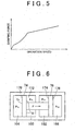
- the hard valve 214 When the fluid pressure of the intermediate chamber 218 becomes higher than the fluid pressure of the fluid chamber 56 by a valve opening pressure of the hard valve 214 or more, the hard valve 214 is opened. As a result, the operating fluid flows to the fluid chamber 56 through the soft valve 216 or the soft valve bypass passage 230 and the hard valve 214 or the hard valve bypass passage 228. As a result, the damping force is controlled as shown in FIG. 5.
- the fluid pressure of the fluid chamber 56 becomes higher than the fluid pressure of the absorber chamber 54.
- the operating fluid in the fluid chamber 56 flows to the absorber chamber 54 through the hard valve bypass passage 228 or the hard valve 214 and the soft valve bypass passage 230 or the soft valve 216.
- the soft valve 216 the outer peripheral side portion of the leaf valve 252 is deflected.
- the outer peripheral side portion of the leaf valve 238 is deflected.
- the damping force is controlled such that the damping force while the piston rod 53 is entering the housing 50 changes in the similar manner as the damping force while the piston rod 53 is being retracted from the housing 50 although the degree of the damping force while the piston rod 53 is entering the housing 50 is different from the degree of the damping force while the piston rod 53 is being retracted from the housing 50.
- the fluid pressure of the absorber chamber 54' of the shock absorber 20 corresponding to the left front wheel 10 and the fluid pressure of the absorber chamber 54 of the shock absorber 24 corresponding to the left rear wheel 14 increase, and the fluid pressure of the absorber chamber 54 of the shock absorber 22 corresponding to the right front wheel 12 and the fluid pressure of the absorber chamber 54 of the shock absorber 26 corresponding to the right rear wheel 16 decrease.
- the fluid pressure which is applied to the outer side pressure-receiving surface 170 and the fluid pressure which is applied to the inner side pressure-receiving surface 172 increase, and the fluid pressure which is applied to the inner side pressure-receiving surface 174 and the fluid pressure which is applied to the outer side pressure-receiving surface 176 decrease.
- the piston assembly 72 moves as follows.
- ⁇ P R is a fluid pressure difference which occurs between the absorber chamber 54 of the shock absorber 24 corresponding to the left rear wheel 14 and the absorber chamber 54 of the shock absorber 26 corresponding to the right rear wheel 16
- ⁇ P F is a fluid pressure difference which occurs between the absorber chamber 54 of the shock absorber 20 corresponding to the left front wheel 10 and the absorber chamber 54 of the shock absorber 22 corresponding to the right front wheel 12.
- the damping characteristics of the shock absorbers 20 to 26 and the pressure-receiving areas S R and S F of each of the pistons 74 and 76 are set such that, in the early stage of steering for left turn, that is, while a rolling speed V is low, ⁇ P R ⁇ S R ⁇ P F ⁇ S F is satisfied, and ⁇ P R ⁇ S R > ⁇ P F ⁇ S F is satisfied during the other times.
- ⁇ P R ⁇ S R > ⁇ P F ⁇ S F is satisfied during the other times.
- ⁇ P R ⁇ S R and ⁇ P F ⁇ S F are shown on the assumption that the form of a characteristic line of the damping force when each of the shock absorber 20 to 26 is being extended is the same as the form of a characteristic line of the damping force when each of the shock absorbers 20 to 26 is being compressed (positions of bend points in the horizontal axis direction) though the degree of the damping force when each of the shock absorber 20 to 26 is being extended is different from the degree of the damping force when each of the shock absorbers 20 to 26 is being compressed, for the purpose of simplifying the description.
- the forms of the characteristic lines are usually different.
- the lines showing ⁇ P R ⁇ S R and ⁇ P F ⁇ S F are similar to the sum of the characteristic line when each of the shock absorbers 20 to 26 is being extended and the characteristic line when each of the shock absorber 20 to 26 is being compressed, and there are more the bend points.
- the piston assembly 72 initially moves leftward and then moves rightward, as shown in FIG. 8. Namely, the damping force on the rear wheel side is increased at the early stage of rolling and then the damping force on the front wheel side is increased, as compared to the case where the control cylinder 30 is not provided.
- the percentage of the damping force on the rear wheel side is high, i.e., the damping force on the rear wheel side increases, at the early stage of steering, and then the percentage of the damping force on the front wheel side is high, i.e., the damping force on the front wheel side increases. If the percentage of the damping force on the rear wheel side is made high at the early stage of steering, steering response of the vehicle is increased. In the steering limit region, if the percentage of the damping force on the front wheel side is made high, occurrence of spin is suppressed, which is advantageous to securing of the stability. According to the embodiment, it is easy to satisfy the requirement.
- the fluid pressure which is applied to the outer side pressure-receiving surface 170 and the fluid pressure which is applied to the outer side pressure-receiving surface 176 increase, and the fluid pressure which is applied to the inner side pressure-receiving surface 172 and the fluid pressure which is applied to the inner side pressure-receiving surface 174 decrease.
- the amount of increase in the fluid pressure of the absorber chambers 54 of the shock absorbers 20 corresponding to the left front wheel 10 is substantially equal to the amount of increase in the fluid pressure of the absorber chamber 54 of the shock absorber 22 corresponding to the right front wheel 12, and the fluid pressures are applied to the inner side pressure-receiving surfaces 172 and 174.
- the amount of decrease in the fluid pressure of the absorber chambers 54 of the shock absorber 24 corresponding to the left rear wheel 14 is substantially equal to the amount of decrease in the fluid pressure of the absorber chamber 54 of the shock absorber 26 corresponding to the right rear wheel 16 are substantially, and the fluid pressures are applied to the outer side pressure-receiving surfaces 170 and 176. Therefore, the balance of the forces applied to the piston assembly 72 does not change, and the piston assembly 72 does not move.
- the shock absorbers 20 to 26 are substantially independent of each other.
- a large damping force can be obtained in each of the shock absorbers 20 to 26 in accordance with a relative movement of the wheel side member 40 and the vehicle body side member 42 (in accordance with a movement of the piston 52), and the pitching speed of the vehicle can be suppressed.
- the left front wheel 10 runs on a bump on a road, namely, when a force that is applied in the direction in which the distance between the wheel side member 40 and the vehicle body side member 42 decreases is increased, or when a force, which moves the wheels diagonally opposite to each other in the same direction, is increased, for example, when a force that is applied to the shock absorbers 20 and 26 and that is applied in the direction in which the distance between the wheel side member 40 and the vehicle body side member 42 decreases is increased, the fluid pressure of the absorber chambers 54 of each of the shock absorbers 20 and 26 decreases, and the fluid pressure of the absorber chambers 54 of each of the shock absorbers 22 and 24 increases.
- the vehicle suspension system it is possible to permit easy movement of one wheel or easy movement of the wheels diagonally opposite to each other in the same direction, and suppress pitching.
- the percentage of the damping force on the rear wheel side is increased at the early stage of turning (at the beginning of turning), and then the percentage of the damping force on the front wheel side is increased by the operation of the control cylinder 30. Therefore, it is possible to make the percentage of the damping force on the rear wheel side high in the early stage of turning, and then make the percentage of the damping force on the front wheel side high.
Landscapes
- Engineering & Computer Science (AREA)
- Mechanical Engineering (AREA)
- Vehicle Body Suspensions (AREA)
- Fluid-Damping Devices (AREA)
- Vibration Prevention Devices (AREA)
Applications Claiming Priority (2)
| Application Number | Priority Date | Filing Date | Title |
|---|---|---|---|
| JP2004114366 | 2004-04-08 | ||
| JP2004114366A JP4151599B2 (ja) | 2004-04-08 | 2004-04-08 | 車両懸架システム |
Publications (3)
| Publication Number | Publication Date |
|---|---|
| EP1584503A2 true EP1584503A2 (fr) | 2005-10-12 |
| EP1584503A3 EP1584503A3 (fr) | 2006-02-08 |
| EP1584503B1 EP1584503B1 (fr) | 2008-09-24 |
Family
ID=34909524
Family Applications (1)
| Application Number | Title | Priority Date | Filing Date |
|---|---|---|---|
| EP05004468A Expired - Fee Related EP1584503B1 (fr) | 2004-04-08 | 2005-03-01 | Système de suspension pour véhicule automobile |
Country Status (5)
| Country | Link |
|---|---|
| US (1) | US7390001B2 (fr) |
| EP (1) | EP1584503B1 (fr) |
| JP (1) | JP4151599B2 (fr) |
| CN (1) | CN1680126B (fr) |
| DE (1) | DE602005009885D1 (fr) |
Cited By (2)
| Publication number | Priority date | Publication date | Assignee | Title |
|---|---|---|---|---|
| EP1879760A4 (fr) * | 2005-03-01 | 2009-05-06 | Kinetic Pty Ltd | Système hydraulique pour suspension de véhicule |
| LU100932B1 (en) * | 2018-09-21 | 2020-03-23 | Faymonville Distrib Ag | Semi-trailer for transporting a load to be moved |
Families Citing this family (22)
| Publication number | Priority date | Publication date | Assignee | Title |
|---|---|---|---|---|
| DE202004013017U1 (de) * | 2004-08-19 | 2004-12-30 | Trw Automotive Gmbh | Wankregelungsstellantrieb |
| US7621382B2 (en) * | 2006-06-28 | 2009-11-24 | Nissan Technical Center North America, Inc. | Shock absorber |
| JP4770712B2 (ja) * | 2006-11-16 | 2011-09-14 | トヨタ自動車株式会社 | サスペンション装置 |
| WO2010016644A1 (fr) * | 2008-08-04 | 2010-02-11 | Jeong Man Hee | Dispositif de reglage du niveau d’un vehicule au moyen d’amortisseurs |
| US8167318B2 (en) * | 2009-09-21 | 2012-05-01 | Msi Defense Solutions, Llc | Hydraulic anti-roll system |
| CN102653221A (zh) * | 2012-04-09 | 2012-09-05 | 王运举 | 带转向自动平衡的减震系统 |
| DE102012112466B4 (de) * | 2012-12-18 | 2023-07-06 | Dr. Ing. H.C. F. Porsche Aktiengesellschaft | Vorrichtung zur Kompensation von Aufbaubewegungen |
| CN103264636B (zh) * | 2013-04-28 | 2015-08-05 | 淄博正邦知识产权企划有限公司 | 平稳转向与易制动的高续航式电动车辆 |
| EP3094514B1 (fr) | 2013-12-23 | 2020-12-02 | Rego Vehicles Ltd. | Système d'absorbeur de chocs de véhicule et accessoire pour ce dernier |
| CN103742584B (zh) * | 2014-01-27 | 2015-12-30 | 安徽柳工起重机有限公司 | 连通式车辆油气悬架阻尼阀 |
| USD802925S1 (en) | 2016-04-29 | 2017-11-21 | Sterilite Corporation | Basket |
| CN106671726B (zh) * | 2016-12-20 | 2019-05-31 | 江苏大学 | 一种叶轮式馈能悬架 |
| CN106904057A (zh) * | 2017-04-12 | 2017-06-30 | 管中林 | 一种具有稳定互联悬架的打药机 |
| CN109318675B (zh) * | 2018-08-23 | 2022-03-22 | 江苏大学 | 一种互联式isd悬架 |
| CN111070989A (zh) * | 2018-10-18 | 2020-04-28 | 湖北火鑫消防车辆装备有限公司 | 车体自行平衡系统 |
| US10967698B2 (en) * | 2018-12-10 | 2021-04-06 | GM Global Technology Operations LLC | Self-balancing multi-chamber air spring |
| CN110370884B (zh) * | 2019-08-27 | 2024-07-30 | 常州万安汽车部件科技有限公司 | 平衡装置及车辆液压互联悬架系统 |
| CN110552429B (zh) * | 2019-08-27 | 2021-01-19 | 天津大学 | 带自平衡的三维隔震抗摇摆装置及方法 |
| US11511583B2 (en) * | 2021-04-05 | 2022-11-29 | Kjell Robt Waerstad | Suspension system |
| CN116409100B (zh) * | 2021-12-30 | 2025-01-14 | 比亚迪股份有限公司 | 液压悬架系统及具有其的车辆 |
| US12220963B2 (en) * | 2023-04-18 | 2025-02-11 | DRiV Automotive Inc. | Modular load distribution unit and assembly method |
| US12269311B2 (en) * | 2023-04-18 | 2025-04-08 | DRiV Automotive Inc. | Dual tube load distribution unit for vehicle suspension system |
Citations (1)
| Publication number | Priority date | Publication date | Assignee | Title |
|---|---|---|---|---|
| US3024037A (en) | 1956-10-16 | 1962-03-06 | Daimler Benz Ag | Wheel suspension and compensating mechanism for vehicles |
Family Cites Families (17)
| Publication number | Priority date | Publication date | Assignee | Title |
|---|---|---|---|---|
| US2184202A (en) * | 1937-12-28 | 1939-12-19 | Carl A Tschanz | Stabilizing system for vehicles |
| DE1214553B (de) * | 1957-11-26 | 1966-04-14 | Daimler Benz Ag | Ausgleichs- und Abfederungseinrichtung fuer vierraedrige Fahrzeuge, insbesondere Kraftfahrzeuge |
| JPS5239524B2 (fr) * | 1973-04-09 | 1977-10-05 | ||
| DE2810629A1 (de) | 1978-03-11 | 1979-09-20 | Weserhuette Ag Eisenwerk | Hydraulische 4-punkt-abstuetzung |
| GB2071587B (en) * | 1980-03-05 | 1983-11-02 | Lucas Industries Ltd | Vehicle suspension system |
| DE3533540A1 (de) | 1984-10-03 | 1986-04-10 | Volkswagen AG, 3180 Wolfsburg | Stabilisatoreinrichtung fuer kraftfahrzeuge |
| DE3618055A1 (de) | 1985-06-07 | 1986-12-11 | Volkswagen AG, 3180 Wolfsburg | Pneumatische oder hydropneumatische federung eines kraftfahrzeugs |
| JPH01269606A (ja) | 1988-04-20 | 1989-10-27 | Honda Motor Co Ltd | サスペンション装置 |
| JPH035224A (ja) * | 1989-05-31 | 1991-01-11 | Chuo Spring Co Ltd | 車輌用スタビライザ装置 |
| FR2663267B1 (fr) | 1990-06-13 | 1994-11-04 | Renault | Suspension hydropneumatique, notamment pour vehicule automobile. |
| EP0599882B1 (fr) * | 1991-07-16 | 1997-11-12 | Kinetic Limited | Suspension de vehicule |
| US5562305A (en) * | 1991-12-18 | 1996-10-08 | Kinetic Limited | Vehicle suspension system |
| DE4231641C2 (de) * | 1992-09-22 | 1996-12-12 | Daimler Benz Ag | Federbein für Federungssysteme von Kraftfahrzeugen |
| JP3640987B2 (ja) | 1994-08-05 | 2005-04-20 | ヤマハ発動機株式会社 | 4輪車用懸架装置 |
| US5785344A (en) * | 1996-01-22 | 1998-07-28 | Tenneco Automotive Inc. | Active roll control |
| US6270098B1 (en) * | 1996-10-31 | 2001-08-07 | Kinetic Limited | Load distribution unit for vehicle suspension system |
| AUPO625897A0 (en) | 1997-04-17 | 1997-05-15 | Kinetic Limited | Improvements to vehicle suspension systems |
-
2004
- 2004-04-08 JP JP2004114366A patent/JP4151599B2/ja not_active Expired - Fee Related
-
2005
- 2005-02-28 US US11/067,638 patent/US7390001B2/en not_active Expired - Fee Related
- 2005-03-01 DE DE602005009885T patent/DE602005009885D1/de not_active Expired - Lifetime
- 2005-03-01 EP EP05004468A patent/EP1584503B1/fr not_active Expired - Fee Related
- 2005-04-08 CN CN200510063299.6A patent/CN1680126B/zh not_active Expired - Fee Related
Patent Citations (1)
| Publication number | Priority date | Publication date | Assignee | Title |
|---|---|---|---|---|
| US3024037A (en) | 1956-10-16 | 1962-03-06 | Daimler Benz Ag | Wheel suspension and compensating mechanism for vehicles |
Cited By (5)
| Publication number | Priority date | Publication date | Assignee | Title |
|---|---|---|---|---|
| EP1879760A4 (fr) * | 2005-03-01 | 2009-05-06 | Kinetic Pty Ltd | Système hydraulique pour suspension de véhicule |
| US8123235B2 (en) | 2005-03-01 | 2012-02-28 | Kinetic Pty. Ltd. | Hydraulic system for a vehicle suspension |
| LU100932B1 (en) * | 2018-09-21 | 2020-03-23 | Faymonville Distrib Ag | Semi-trailer for transporting a load to be moved |
| WO2020058934A1 (fr) | 2018-09-21 | 2020-03-26 | Faymonville Distribution Ag | Semi-remorque permettant de transporter une charge à déplacer |
| US12030562B2 (en) | 2018-09-21 | 2024-07-09 | Faymonville Distribution Ag | Semi-trailer for transporting a load to be moved |
Also Published As
| Publication number | Publication date |
|---|---|
| JP2005297680A (ja) | 2005-10-27 |
| US7390001B2 (en) | 2008-06-24 |
| CN1680126A (zh) | 2005-10-12 |
| CN1680126B (zh) | 2012-04-11 |
| US20050225050A1 (en) | 2005-10-13 |
| EP1584503A3 (fr) | 2006-02-08 |
| JP4151599B2 (ja) | 2008-09-17 |
| EP1584503B1 (fr) | 2008-09-24 |
| DE602005009885D1 (de) | 2008-11-06 |
Similar Documents
| Publication | Publication Date | Title |
|---|---|---|
| US7390001B2 (en) | Vehicle suspension system | |
| US7686309B2 (en) | Hydraulic system for a vehicle suspension | |
| US6290035B1 (en) | Acceleration sensitive damping for automotive dampers | |
| CN101796322B (zh) | 接合式泄放装置 | |
| US6981578B2 (en) | Non-pressurized monotube shock absorber | |
| US7637516B2 (en) | Vehicular suspension system | |
| CN101541571B (zh) | 具有无级半主动阀的减振器 | |
| CN102307738B (zh) | 具有缩短的中间管的三管减震器 | |
| US6332622B1 (en) | Suspension apparatus having two interconnected shock absorbers | |
| US6871845B2 (en) | Self-pumping, hydropneumatic suspension strut unit | |
| US20120119454A1 (en) | Active suspension system and hydraulic ram therefor | |
| JP2001074082A (ja) | 懸架減衰装置 | |
| JP3391487B2 (ja) | 4輪車用懸架装置 | |
| US5226512A (en) | Variable damping force shock absorber with variable orifice for adjusting damping characteristics | |
| JP2985707B2 (ja) | セルフポンピング式ショックアブソーバ | |
| JP3347597B2 (ja) | 車両用懸架装置 | |
| JPH0585372B2 (fr) | ||
| US5788031A (en) | Control cylinder unit for varying spring constant of vehicular stabilizer | |
| US8087646B2 (en) | Hydropneumatic suspension with load-dependent damping control | |
| JP3033456B2 (ja) | セルフポンピング式ショックアブソーバ | |
| JPH02109713A (ja) | サスペンション装置 | |
| JP3033457B2 (ja) | セルフポンピング式ショックアブソーバ | |
| JP4905913B2 (ja) | 車両用油圧式緩衝装置 | |
| JPH0623786Y2 (ja) | 自動車用ラバ−ブッシュのばね特性調整装置 | |
| JP2003159924A (ja) | 車両用サスペンション装置 |
Legal Events
| Date | Code | Title | Description |
|---|---|---|---|
| PUAI | Public reference made under article 153(3) epc to a published international application that has entered the european phase |
Free format text: ORIGINAL CODE: 0009012 |
|
| 17P | Request for examination filed |
Effective date: 20050301 |
|
| AK | Designated contracting states |
Kind code of ref document: A2 Designated state(s): AT BE BG CH CY CZ DE DK EE ES FI FR GB GR HU IE IS IT LI LT LU MC NL PL PT RO SE SI SK TR |
|
| AX | Request for extension of the european patent |
Extension state: AL BA HR LV MK YU |
|
| PUAL | Search report despatched |
Free format text: ORIGINAL CODE: 0009013 |
|
| AK | Designated contracting states |
Kind code of ref document: A3 Designated state(s): AT BE BG CH CY CZ DE DK EE ES FI FR GB GR HU IE IS IT LI LT LU MC NL PL PT RO SE SI SK TR |
|
| AX | Request for extension of the european patent |
Extension state: AL BA HR LV MK YU |
|
| AKX | Designation fees paid |
Designated state(s): DE FR GB |
|
| GRAP | Despatch of communication of intention to grant a patent |
Free format text: ORIGINAL CODE: EPIDOSNIGR1 |
|
| GRAS | Grant fee paid |
Free format text: ORIGINAL CODE: EPIDOSNIGR3 |
|
| GRAA | (expected) grant |
Free format text: ORIGINAL CODE: 0009210 |
|
| RIN1 | Information on inventor provided before grant (corrected) |
Inventor name: MIZUNO, KAZUYUKI |
|
| AK | Designated contracting states |
Kind code of ref document: B1 Designated state(s): DE FR GB |
|
| REG | Reference to a national code |
Ref country code: GB Ref legal event code: FG4D |
|
| REF | Corresponds to: |
Ref document number: 602005009885 Country of ref document: DE Date of ref document: 20081106 Kind code of ref document: P |
|
| PLBE | No opposition filed within time limit |
Free format text: ORIGINAL CODE: 0009261 |
|
| STAA | Information on the status of an ep patent application or granted ep patent |
Free format text: STATUS: NO OPPOSITION FILED WITHIN TIME LIMIT |
|
| 26N | No opposition filed |
Effective date: 20090625 |
|
| REG | Reference to a national code |
Ref country code: GB Ref legal event code: 746 Effective date: 20121219 |
|
| REG | Reference to a national code |
Ref country code: DE Ref legal event code: R084 Ref document number: 602005009885 Country of ref document: DE Effective date: 20121213 |
|
| REG | Reference to a national code |
Ref country code: FR Ref legal event code: PLFP Year of fee payment: 11 |
|
| PGFP | Annual fee paid to national office [announced via postgrant information from national office to epo] |
Ref country code: DE Payment date: 20150224 Year of fee payment: 11 |
|
| PGFP | Annual fee paid to national office [announced via postgrant information from national office to epo] |
Ref country code: GB Payment date: 20150225 Year of fee payment: 11 Ref country code: FR Payment date: 20150309 Year of fee payment: 11 |
|
| REG | Reference to a national code |
Ref country code: DE Ref legal event code: R119 Ref document number: 602005009885 Country of ref document: DE |
|
| GBPC | Gb: european patent ceased through non-payment of renewal fee |
Effective date: 20160301 |
|
| REG | Reference to a national code |
Ref country code: FR Ref legal event code: ST Effective date: 20161130 |
|
| PG25 | Lapsed in a contracting state [announced via postgrant information from national office to epo] |
Ref country code: DE Free format text: LAPSE BECAUSE OF NON-PAYMENT OF DUE FEES Effective date: 20161001 Ref country code: GB Free format text: LAPSE BECAUSE OF NON-PAYMENT OF DUE FEES Effective date: 20160301 Ref country code: FR Free format text: LAPSE BECAUSE OF NON-PAYMENT OF DUE FEES Effective date: 20160331 |