EP1584396B1 - Machine et procédé pour la production d'un rouleau - Google Patents
Machine et procédé pour la production d'un rouleau Download PDFInfo
- Publication number
- EP1584396B1 EP1584396B1 EP05004239A EP05004239A EP1584396B1 EP 1584396 B1 EP1584396 B1 EP 1584396B1 EP 05004239 A EP05004239 A EP 05004239A EP 05004239 A EP05004239 A EP 05004239A EP 1584396 B1 EP1584396 B1 EP 1584396B1
- Authority
- EP
- European Patent Office
- Prior art keywords
- roller
- roll
- belt
- machining process
- machine
- Prior art date
- Legal status (The legal status is an assumption and is not a legal conclusion. Google has not performed a legal analysis and makes no representation as to the accuracy of the status listed.)
- Revoked
Links
Images

Classifications
-
- B—PERFORMING OPERATIONS; TRANSPORTING
- B23—MACHINE TOOLS; METAL-WORKING NOT OTHERWISE PROVIDED FOR
- B23H—WORKING OF METAL BY THE ACTION OF A HIGH CONCENTRATION OF ELECTRIC CURRENT ON A WORKPIECE USING AN ELECTRODE WHICH TAKES THE PLACE OF A TOOL; SUCH WORKING COMBINED WITH OTHER FORMS OF WORKING OF METAL
- B23H9/00—Machining specially adapted for treating particular metal objects or for obtaining special effects or results on metal objects
- B23H9/04—Treating surfaces of rolls
-
- B—PERFORMING OPERATIONS; TRANSPORTING
- B24—GRINDING; POLISHING
- B24B—MACHINES, DEVICES, OR PROCESSES FOR GRINDING OR POLISHING; DRESSING OR CONDITIONING OF ABRADING SURFACES; FEEDING OF GRINDING, POLISHING, OR LAPPING AGENTS
- B24B21/00—Machines or devices using grinding or polishing belts; Accessories therefor
- B24B21/02—Machines or devices using grinding or polishing belts; Accessories therefor for grinding rotationally symmetrical surfaces
-
- B—PERFORMING OPERATIONS; TRANSPORTING
- B24—GRINDING; POLISHING
- B24B—MACHINES, DEVICES, OR PROCESSES FOR GRINDING OR POLISHING; DRESSING OR CONDITIONING OF ABRADING SURFACES; FEEDING OF GRINDING, POLISHING, OR LAPPING AGENTS
- B24B5/00—Machines or devices designed for grinding surfaces of revolution on work, including those which also grind adjacent plane surfaces; Accessories therefor
- B24B5/02—Machines or devices designed for grinding surfaces of revolution on work, including those which also grind adjacent plane surfaces; Accessories therefor involving centres or chucks for holding work
- B24B5/16—Machines or devices designed for grinding surfaces of revolution on work, including those which also grind adjacent plane surfaces; Accessories therefor involving centres or chucks for holding work for grinding peculiarly surfaces, e.g. bulged
- B24B5/167—Machines or devices designed for grinding surfaces of revolution on work, including those which also grind adjacent plane surfaces; Accessories therefor involving centres or chucks for holding work for grinding peculiarly surfaces, e.g. bulged for rolls with large curvature radius, e.g. mill rolls
Definitions
- the invention relates to a method for producing a roll, wherein the surface of the roll is brought by means of an electric erosion process in the desired contour with a pre-selected roughness and a defined peak number and the electro-erosion process is followed by a finishing process.
- spark erosion of the surface of the roll leads to material removal, with which it is possible to provide the roll surface with a uniform roughness depth (roughness R a ) and a defined number of tips selected in advance.
- an electrode is brought to a precisely controlled gap to the surface of the roller.
- a high-frequency generator supplies the energy in the form of erosion pulses, which lead locally to crater formation distributed over the electrode.
- the conductive particles in the dielectric form a dipole bridge as soon as the pulse voltage acts.
- a stream starts to flow, causing the roll surface a trough-shaped volume of material heated above its melting point and thereby increased.
- a gas bubble forms.
- the discharge channel breaks down, whereby the melted volume is ejected and thus removed. This leaves a trough-shaped depression, resulting in a total of a diffuse structure with maximum programmable uniformity and tight tolerances.
- the rolls are used as tools for shaping and texturing the rolled stock.
- the rollers are subjected to a rolling force in order to achieve a deformation of the rolling stock.
- the rolling behavior of the rolls changed in particular on the first rolling meters. It has been found that in this first operation of a new roll, the over-protruding tips produced during roughening on the roll surfaces break off, resulting in abrasion and contamination of the rolling stock surface. These impurities are undesirable or detrimental to further deformation and coating processes and lead to a considerable scrap of material and additional expense during further processing.
- the invention is therefore based on the object to provide a method by which the manufacturing process for rolls can be simplified.
- the rolls produced should be characterized by an optimal run-in behavior, so that the abovementioned disadvantages are avoided.
- an amount between 1.0 ⁇ m and 20 ⁇ m of material is measured from the surface of the roll measured by the finishing process in the radial direction of the roll. Further, preferably, the average roughness of the surface of the roller is not substantially changed in performing the finishing process.
- the textured rollers can thus be calibrated exactly to the desired bearing level. It ensures high process reliability. Thus, a batch-free, uniform roll surface with an increased load-bearing content and resulting higher wear resistance in the rolling process is possible. The breaking of isolated, otherwise on the average value of the roughness protruding peaks is thereby prevented or reduced to a minimum.
- the entire process for processing the roll surface can be fully automated.
- the manufacturing costs can - compared to today's usual methods - be significantly reduced.
- the rolls thus processed do not require a running-in phase during the rolling process and in particular at the beginning of the rolling process.
- no micro-tips break off on the roll surface, which leads to less abrasion and dirt on the rolling stock and to a longer service life of the roll in the process.
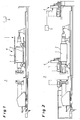
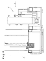
- a processing machine 7 is shown, with which a roller 1 can be manufactured. It is in the processing in the processing machine 7 about to provide the surface 2 of the roller 1 precisely with its final contour.
- the roller is already largely pre-processed and surface-treated (hardened) in the processing machine. 7
- Fig. 1 As only very schematic in Fig. 1 can be seen, the processing machine 7 an electric erosion unit 3, wherein in Fig. 1 a number of electrodes 8 is shown.
- the EDT (spark erosion) method is performed.
- a material removal takes place on the surface 2 of the roller 1, in a geometrically predetermined manner.
- R a roughness
- the electrodes 8 are brought to a precisely controlled gap to the surface 2 of the roller 1.
- the application of a pulse current results in the removal of material particles. Trough-shaped depressions remain on the roll surface, giving overall a diffused structure with a high degree of uniformity at tight tolerances.
- the belt grinding device 4 can be arranged in two different positions in the machine 7, ie, moved there: the right position corresponds to a rest position in which the belt grinding device 4 does not work. In the left position, the belt grinder 4 is moved up to the roller 1 and takes from the surface 2 material from. For this purpose, the belt grinding device 4 is moved in the axial direction of the roller 1.
- the grinding process performed by the belt grinder 4 is adjusted in terms of its operating parameters so that the surface 2 is calibrated according to predetermined target data, i. H. the surface 2 is brought to a desired Traganteilsmat.
- both the electro-erosion unit 3 and the belt grinder 4 are controlled by a common CNC machine control 5, which is shown only very schematically.
- the belt grinding device 4 has a grinding belt 6 which is provided on its surface on one side with an abrasive hard material, for example with corundum or boron nitride.
- the grain of the hard material is chosen so that the desired surface contour is formed on the roller 1.
- Very fine hard material can have a mean particle size in the range of less than 1 ⁇ m, for coarser machining operations with a correspondingly higher removal rate, large particle sizes in the range up to about 50 to 100 ⁇ m are conceivable.
- the abrasive belt 6 is wound on a supply reel 9, from which it is unwound.
- a tape guide 10 guides the tape 6 in the area of the surface 2 of the roller 1. From there, it is passed on to a take-up reel 11, which rewinds the tape 6. It come here tape lengths of 15 to 50 m used.
- the grinding belt 6 is pressed by means of a pressure roller 12 with a pressure force directed radially to the axis of the roller 1 onto the roller surface 2.
- the unwinding speed of the grinding belt 6 from the unwinding roller 9 or onto the take-up reel 11 is predetermined by a controllable drive motor 13.
- the unwinding of the grinding belt 6 is thus speed-controlled by the drive motor 13.
- the feed of the grinding belt 6 - in the axial direction of the roller 1 - is preferably continuously controlled.
- desired surface parameters can be achieved after texturing.
- the average roughness R a does not or hardly changes as a result of the superfinishing process in the form of grinding. Also, the Pc value remains constant.
- the fine processing unit 4 is integrated in the machine 7 for performing the electric erosion. However, it is also possible that the fine processing unit 4 is arranged outside this machine, for example in combination with a measuring or inspection device (not shown).
- the fine processing unit 4 are arranged in a tailstock lid of a tank cover so that the sanding belt 6 can be placed from above on the surface 2 of the roller 1.
- the fine processing unit 4 can be arranged so that the grinding belt 6 is horizontally brought to the surface 2 of the roller 1.
Landscapes
- Engineering & Computer Science (AREA)
- Mechanical Engineering (AREA)
- Physics & Mathematics (AREA)
- Thermal Sciences (AREA)
- Finish Polishing, Edge Sharpening, And Grinding By Specific Grinding Devices (AREA)
- Electrical Discharge Machining, Electrochemical Machining, And Combined Machining (AREA)
- Grinding Of Cylindrical And Plane Surfaces (AREA)
- Reduction Rolling/Reduction Stand/Operation Of Reduction Machine (AREA)
- Rolls And Other Rotary Bodies (AREA)
Claims (3)
- Procédé pour fabriquer un rouleau (1), dans lequel la surface (2) du rouleau (1) est amenée au moyen d'un processus d'électroérosion dans le contour souhaité avec une rugosité choisie à l'avance et un nombre de pointes défini et un processus d'usinage fin est placé en aval du processus d'électroérosion,
caractérisé en ce que
le processus d'usinage fin est un processus d'usinage mécanique avec une lame non définie au plan géométrique et est réalisé comme processus de ponçage à bande abrasive, seules les pointes supérieures affaiblies de la surface de rouleau étant enlevées, de sorte qu'ainsi la rupture de pointes isolées, dépassant par ailleurs de la valeur moyenne de rugosité, de la surface de rouleau est ainsi empêchée dans le processus de laminage et est réduite à un minimum. - Procédé selon la revendication 1,
caractérisé en ce
qu'une valeur comprise entre 1,0 µm et 20 µm de matériau, mesurée dans le sens radial du rouleau (1), est enlevée de la surface (2) du rouleau (1) par le processus d'usinage fin. - Procédé selon la revendication 1 ou 2,
caractérisé en ce que
la rugosité moyenne (Ra) de la surface (2) du rouleau (1) reste sensiblement inchangée lors du processus d'usinage fin.
Priority Applications (1)
| Application Number | Priority Date | Filing Date | Title |
|---|---|---|---|
| PL05004239T PL1584396T3 (pl) | 2004-03-16 | 2005-02-26 | Sposób i maszyna do wytwarzania walca |
Applications Claiming Priority (2)
| Application Number | Priority Date | Filing Date | Title |
|---|---|---|---|
| DE102004013031A DE102004013031A1 (de) | 2004-03-16 | 2004-03-16 | Verfahren und Maschine zur Herstellung einer Walze |
| DE102004013031 | 2004-03-16 |
Publications (3)
| Publication Number | Publication Date |
|---|---|
| EP1584396A2 EP1584396A2 (fr) | 2005-10-12 |
| EP1584396A3 EP1584396A3 (fr) | 2006-08-16 |
| EP1584396B1 true EP1584396B1 (fr) | 2011-06-15 |
Family
ID=34895414
Family Applications (1)
| Application Number | Title | Priority Date | Filing Date |
|---|---|---|---|
| EP05004239A Revoked EP1584396B1 (fr) | 2004-03-16 | 2005-02-26 | Machine et procédé pour la production d'un rouleau |
Country Status (7)
| Country | Link |
|---|---|
| US (1) | US7189145B2 (fr) |
| EP (1) | EP1584396B1 (fr) |
| CN (1) | CN1669730A (fr) |
| AT (1) | ATE512742T1 (fr) |
| DE (1) | DE102004013031A1 (fr) |
| ES (1) | ES2367642T3 (fr) |
| PL (1) | PL1584396T3 (fr) |
Families Citing this family (14)
| Publication number | Priority date | Publication date | Assignee | Title |
|---|---|---|---|---|
| US20070141964A1 (en) * | 2005-12-19 | 2007-06-21 | Dan Zimmerman | Work rolls surface textured by media blasting and controlled surface modification |
| US20070137038A1 (en) * | 2005-12-19 | 2007-06-21 | Barr Rodney S | Work rolls having an engineered surface texture prepared by controlled surface modification after chrome coating |
| DE502007004723D1 (de) | 2007-06-22 | 2010-09-23 | Laser Walzen Ct Gmbh | Flachprodukt aus einem Metallwerkstoff, insbesondere einem Stahlwerkstoff, Verwendung eines solchen Flachprodukts sowie Walze und Verfahren zur Herstellung solcher Flachprodukte |
| DE102009003140A1 (de) | 2009-05-15 | 2010-11-18 | Voith Patent Gmbh | Schleifvorrichtung für Walzen |
| DE102010046558B3 (de) * | 2010-09-27 | 2012-03-15 | H. Kleinknecht & Co. Gmbh | Vorrichtung zum Texturieren einer Walze |
| DE102010046559B4 (de) * | 2010-09-27 | 2013-02-07 | H. Kleinknecht & Co. Gmbh | Vorrichtung zum Texturieren einer Walze |
| JP6085391B2 (ja) | 2013-03-15 | 2017-02-22 | ノベリス・インコーポレイテッドNovelis Inc. | ダル光沢仕上げの圧延肌 |
| CN105290547B (zh) * | 2014-07-11 | 2017-09-26 | 鞍钢股份有限公司 | 一种低粗糙度高峰值数毛化轧辊的加工方法 |
| TR201905219T4 (tr) | 2014-10-09 | 2019-05-21 | Thyssenkrupp Ag | Soğuk haddelenen ve yeniden kristalleştirilen şekilde tavlanan yassı çelik ürünü ve bunun üretilmesine yönelik yöntem. |
| CN109158893B (zh) * | 2018-10-22 | 2019-12-13 | 温州万兴制版有限公司 | 一种轧辊的表面处理装置 |
| DE102019214135A1 (de) * | 2019-09-17 | 2021-03-18 | Thyssenkrupp Steel Europe Ag | Stahlblech mit einer deterministischen Oberflächenstruktur |
| DE102019214136A1 (de) | 2019-09-17 | 2021-03-18 | Thyssenkrupp Steel Europe Ag | Stahlblech mit einer deterministischen Oberflächenstruktur |
| CN113798927A (zh) * | 2020-06-15 | 2021-12-17 | 重庆大学 | 一种电场辅助砂带磨削方法 |
| CN111889522B (zh) * | 2020-08-20 | 2022-05-31 | 中铝瑞闽股份有限公司 | 一种提高铝板带轧制表面质量的控制方法 |
Family Cites Families (20)
| Publication number | Priority date | Publication date | Assignee | Title |
|---|---|---|---|---|
| US2334572A (en) * | 1941-12-29 | 1943-11-16 | Carborundum Co | Manufacture of abrasive materials |
| US3520089A (en) * | 1967-07-19 | 1970-07-14 | Carborundum Co | Grinding machine |
| US3878353A (en) * | 1968-12-05 | 1975-04-15 | Ingersoll Milling Machine Co | Method for finishing rolls |
| CA925573A (en) * | 1968-12-05 | 1973-05-01 | L. Anderson Alex | Methods and apparatus for finishing rolls |
| JPS59169720A (ja) * | 1983-03-16 | 1984-09-25 | Inoue Japax Res Inc | 電気加工用マシニングセンタ |
| DE3717568A1 (de) * | 1987-05-25 | 1988-12-08 | Lach Spezial Werkzeuge Gmbh | Verfahren und vorrichtung zum mechanischen schleifen von werkstuecken mittels elektrisch leitfaehiger schleifwerkzeuge |
| SE462078B (sv) * | 1988-09-16 | 1990-05-07 | Tom Nordquist | Saett foer bandslipning av aemnen av metaller och metallegeringar |
| US5025547A (en) * | 1990-05-07 | 1991-06-25 | Aluminum Company Of America | Method of providing textures on material by rolling |
| US5189843A (en) * | 1990-08-30 | 1993-03-02 | Silicon Technology Corporation | Wafer slicing and grinding machine and a method of slicing and grinding wafers |
| DE4227315C2 (de) * | 1991-08-19 | 1995-03-09 | Grieshaber Masch | Maschine zum Schleifen, Kurzhubhonen und Polieren der Außenoberfläche von Werkstücken |
| US5537851A (en) * | 1993-01-05 | 1996-07-23 | Aluminum Company Of America | Sheet product produced by massive reduction in last stand of cold rolling process |
| US5508119A (en) * | 1994-09-07 | 1996-04-16 | Aluminum Company Of America | Enhanced work roll surface texture for cold and hot rolling of aluminum and its alloys |
| US5816892A (en) * | 1997-02-06 | 1998-10-06 | Cobra Machine Tool Co., Inc. | Positioning control for combined milling machine and internally positioned grinding wheel |
| JP2000247668A (ja) * | 1999-02-25 | 2000-09-12 | Bando Kiko Kk | ガラス板の加工機械 |
| DE10065881A1 (de) * | 2000-12-23 | 2002-07-04 | Jaeger Gmbh Roll Service | Vorrichtung zum Schleifen einer Außenmantelfläche |
| DE10155078B4 (de) * | 2001-11-09 | 2005-06-02 | Walter Ag | Maschine mit temperaturkompensierter Arbeitsspindel |
| US6722959B2 (en) * | 2002-03-22 | 2004-04-20 | Glassline Corporation | Combination 2-plane CNC positioning grinder with CNC positioning drill |
| US6717094B2 (en) * | 2002-07-22 | 2004-04-06 | Edward L. Beaumont | Electrical discharge machine and methods of establishing zero set conditions for operation thereof |
| US20050218089A1 (en) * | 2004-03-30 | 2005-10-06 | General Electric Company | Flushing and filtering system for electroerosion machining |
| US20050247569A1 (en) * | 2004-05-07 | 2005-11-10 | Lamphere Michael S | Distributed arc electroerosion |
-
2004
- 2004-03-16 DE DE102004013031A patent/DE102004013031A1/de not_active Withdrawn
-
2005
- 2005-02-26 EP EP05004239A patent/EP1584396B1/fr not_active Revoked
- 2005-02-26 ES ES05004239T patent/ES2367642T3/es active Active
- 2005-02-26 PL PL05004239T patent/PL1584396T3/pl unknown
- 2005-02-26 AT AT05004239T patent/ATE512742T1/de active
- 2005-03-15 US US11/082,214 patent/US7189145B2/en active Active
- 2005-03-16 CN CNA2005100558127A patent/CN1669730A/zh active Pending
Also Published As
| Publication number | Publication date |
|---|---|
| US20050227594A1 (en) | 2005-10-13 |
| DE102004013031A1 (de) | 2005-10-06 |
| EP1584396A2 (fr) | 2005-10-12 |
| EP1584396A3 (fr) | 2006-08-16 |
| ATE512742T1 (de) | 2011-07-15 |
| CN1669730A (zh) | 2005-09-21 |
| ES2367642T3 (es) | 2011-11-07 |
| PL1584396T3 (pl) | 2011-11-30 |
| US7189145B2 (en) | 2007-03-13 |
Similar Documents
| Publication | Publication Date | Title |
|---|---|---|
| EP1584396B1 (fr) | Machine et procédé pour la production d'un rouleau | |
| DE19632463C2 (de) | Vorrichtung und Verfahren zur Formgebung von Schleifscheiben | |
| DE3707664C1 (de) | Werkzeugmaschine zum Feinbearbeiten der Zahnflanken von vorverzahnten Zahnraedern | |
| DE69009890T2 (de) | Verfahren und einrichtung zum feinbearbeiten und supfinieren. | |
| DE69721881T2 (de) | Drahtsäge und Verfahren zum Zerschneiden eines zylindrischen Werkstücks, wie Ingots | |
| DE4436663C2 (de) | Verfahren und Vorrichtung zur Bildung einer Änderungsschicht auf einer Metalloberfläche | |
| EP0909611B1 (fr) | Procédé pour meuler les surfaces de pièces et dispositif pour la mise en oeuvre du procédé | |
| DE112014003483T5 (de) | Verfahren zum In-Scheiben-Schneiden von Rohblöcken und Drahtsäge | |
| DE3509340A1 (de) | Verfahren und vorrichtung zur endbearbeitung von stirnflaechenkollektoren | |
| DE3122205A1 (de) | Vorrichtung zum leiten von bearbeitungsstrom zu einem drahtelektrodenwerkzeug in einer drahtschneidelektroerosionsmaschine | |
| DE102015204909A1 (de) | Verfahren und Schleifmaschine zum Schleifen von Nuten aufweisenden Werkstücken | |
| DE10131668B4 (de) | Verfahren zur abrasiven Bearbeitung von Oberflächen, auf Halbleiter-Wafern | |
| DE2830791A1 (de) | Verfahren und vorrichtung zur elektroerosiven bearbeitung von zylindrischen werkstuecken | |
| EP0103062B1 (fr) | Procédé et dispositif pour l'affûtage d'une meule | |
| DE69414335T2 (de) | Vorrichtung zum Herstellen von geschliffenen Hohlnadeln | |
| EP3829813B1 (fr) | Dispositif et procédé destinés à traiter une pièce à usiner, en particulier une pièce à usiner pourvue de lames, au moyen d'un outil d'abrasion ou d'érosion | |
| CH691442A5 (de) | Verfahren und Maschine zum Honen von Kleinstlöchern. | |
| DE202020004003U1 (de) | Werkzeugmaschine zur Laserkonditionierung von Schleifwerkzeugen unabhängig von deren Spezifikation | |
| DE1961676C3 (de) | Verfahren und Vorrichtung zur Bearbeitung einer aus gehärtetem Stahl bestehenden Walze mittels Elektroerosion | |
| DD209406B1 (de) | Verfahren fuer die schleiftechnische bearbeitung von werkstuecken mit komplizierten bearbeitungsbedingungen auf innenrundschleifmaschinen | |
| DE8916001U1 (de) | Vorrichtung zur materialabhebenden Fein- oder Feinstbearbeitung | |
| DE4121518C2 (de) | Verfahren für die Feinbearbeitung von Werkstückoberflächen | |
| EP1208943A1 (fr) | Dispositif et procédé pour dresser une meule à liaison métal | |
| DE10333500A1 (de) | Verfahren und Vorrichtung zum Glätten von Werkstück-Oberflächen | |
| DE102009008811B4 (de) | Konditioniervorrichtung zum Konditionieren einer Schleifscheibe und Verfahren zum Konditionieren einer Schleifscheibe |
Legal Events
| Date | Code | Title | Description |
|---|---|---|---|
| PUAI | Public reference made under article 153(3) epc to a published international application that has entered the european phase |
Free format text: ORIGINAL CODE: 0009012 |
|
| AK | Designated contracting states |
Kind code of ref document: A2 Designated state(s): AT BE BG CH CY CZ DE DK EE ES FI FR GB GR HU IE IS IT LI LT LU MC NL PL PT RO SE SI SK TR |
|
| AX | Request for extension of the european patent |
Extension state: AL BA HR LV MK YU |
|
| RAP1 | Party data changed (applicant data changed or rights of an application transferred) |
Owner name: COURT HOLDING LIMITED Owner name: WALDRICH SIEGEN WERKZEUGMASCHINENBAU GMBH |
|
| PUAL | Search report despatched |
Free format text: ORIGINAL CODE: 0009013 |
|
| AK | Designated contracting states |
Kind code of ref document: A3 Designated state(s): AT BE BG CH CY CZ DE DK EE ES FI FR GB GR HU IE IS IT LI LT LU MC NL PL PT RO SE SI SK TR |
|
| AX | Request for extension of the european patent |
Extension state: AL BA HR LV MK YU |
|
| 17P | Request for examination filed |
Effective date: 20070208 |
|
| AKX | Designation fees paid |
Designated state(s): AT BE BG CH CY CZ DE DK EE ES FI FR GB GR HU IE IS IT LI LT LU MC NL PL PT RO SE SI SK TR |
|
| 17Q | First examination report despatched |
Effective date: 20080807 |
|
| GRAP | Despatch of communication of intention to grant a patent |
Free format text: ORIGINAL CODE: EPIDOSNIGR1 |
|
| GRAS | Grant fee paid |
Free format text: ORIGINAL CODE: EPIDOSNIGR3 |
|
| GRAA | (expected) grant |
Free format text: ORIGINAL CODE: 0009210 |
|
| AK | Designated contracting states |
Kind code of ref document: B1 Designated state(s): AT BE BG CH CY CZ DE DK EE ES FI FR GB GR HU IE IS IT LI LT LU MC NL PL PT RO SE SI SK TR |
|
| REG | Reference to a national code |
Ref country code: GB Ref legal event code: FG4D Free format text: NOT ENGLISH Ref country code: CH Ref legal event code: EP |
|
| REG | Reference to a national code |
Ref country code: IE Ref legal event code: FG4D Free format text: LANGUAGE OF EP DOCUMENT: GERMAN |
|
| REG | Reference to a national code |
Ref country code: DE Ref legal event code: R096 Ref document number: 502005011489 Country of ref document: DE Effective date: 20110728 |
|
| REG | Reference to a national code |
Ref country code: RO Ref legal event code: EPE |
|
| REG | Reference to a national code |
Ref country code: SE Ref legal event code: TRGR |
|
| REG | Reference to a national code |
Ref country code: NL Ref legal event code: T3 |
|
| PG25 | Lapsed in a contracting state [announced via postgrant information from national office to epo] |
Ref country code: LT Free format text: LAPSE BECAUSE OF FAILURE TO SUBMIT A TRANSLATION OF THE DESCRIPTION OR TO PAY THE FEE WITHIN THE PRESCRIBED TIME-LIMIT Effective date: 20110615 |
|
| REG | Reference to a national code |
Ref country code: ES Ref legal event code: FG2A Ref document number: 2367642 Country of ref document: ES Kind code of ref document: T3 Effective date: 20111107 |
|
| PG25 | Lapsed in a contracting state [announced via postgrant information from national office to epo] |
Ref country code: FI Free format text: LAPSE BECAUSE OF FAILURE TO SUBMIT A TRANSLATION OF THE DESCRIPTION OR TO PAY THE FEE WITHIN THE PRESCRIBED TIME-LIMIT Effective date: 20110615 Ref country code: CY Free format text: LAPSE BECAUSE OF FAILURE TO SUBMIT A TRANSLATION OF THE DESCRIPTION OR TO PAY THE FEE WITHIN THE PRESCRIBED TIME-LIMIT Effective date: 20110615 Ref country code: GR Free format text: LAPSE BECAUSE OF FAILURE TO SUBMIT A TRANSLATION OF THE DESCRIPTION OR TO PAY THE FEE WITHIN THE PRESCRIBED TIME-LIMIT Effective date: 20110916 Ref country code: SI Free format text: LAPSE BECAUSE OF FAILURE TO SUBMIT A TRANSLATION OF THE DESCRIPTION OR TO PAY THE FEE WITHIN THE PRESCRIBED TIME-LIMIT Effective date: 20110615 |
|
| REG | Reference to a national code |
Ref country code: PL Ref legal event code: T3 |
|
| REG | Reference to a national code |
Ref country code: SK Ref legal event code: T3 Ref document number: E 10101 Country of ref document: SK |
|
| REG | Reference to a national code |
Ref country code: IE Ref legal event code: FD4D |
|
| PG25 | Lapsed in a contracting state [announced via postgrant information from national office to epo] |
Ref country code: IS Free format text: LAPSE BECAUSE OF FAILURE TO SUBMIT A TRANSLATION OF THE DESCRIPTION OR TO PAY THE FEE WITHIN THE PRESCRIBED TIME-LIMIT Effective date: 20111015 Ref country code: PT Free format text: LAPSE BECAUSE OF FAILURE TO SUBMIT A TRANSLATION OF THE DESCRIPTION OR TO PAY THE FEE WITHIN THE PRESCRIBED TIME-LIMIT Effective date: 20111017 Ref country code: IE Free format text: LAPSE BECAUSE OF FAILURE TO SUBMIT A TRANSLATION OF THE DESCRIPTION OR TO PAY THE FEE WITHIN THE PRESCRIBED TIME-LIMIT Effective date: 20110615 Ref country code: EE Free format text: LAPSE BECAUSE OF FAILURE TO SUBMIT A TRANSLATION OF THE DESCRIPTION OR TO PAY THE FEE WITHIN THE PRESCRIBED TIME-LIMIT Effective date: 20110615 |
|
| PLBI | Opposition filed |
Free format text: ORIGINAL CODE: 0009260 |
|
| 26 | Opposition filed |
Opponent name: H. KLEINKNECHT & CO. GMBH Effective date: 20120313 |
|
| PLAX | Notice of opposition and request to file observation + time limit sent |
Free format text: ORIGINAL CODE: EPIDOSNOBS2 |
|
| PGFP | Annual fee paid to national office [announced via postgrant information from national office to epo] |
Ref country code: TR Payment date: 20120213 Year of fee payment: 8 |
|
| REG | Reference to a national code |
Ref country code: DE Ref legal event code: R026 Ref document number: 502005011489 Country of ref document: DE Effective date: 20120313 |
|
| PG25 | Lapsed in a contracting state [announced via postgrant information from national office to epo] |
Ref country code: DK Free format text: LAPSE BECAUSE OF FAILURE TO SUBMIT A TRANSLATION OF THE DESCRIPTION OR TO PAY THE FEE WITHIN THE PRESCRIBED TIME-LIMIT Effective date: 20110615 |
|
| PGFP | Annual fee paid to national office [announced via postgrant information from national office to epo] |
Ref country code: IT Payment date: 20120221 Year of fee payment: 8 |
|
| PLAF | Information modified related to communication of a notice of opposition and request to file observations + time limit |
Free format text: ORIGINAL CODE: EPIDOSCOBS2 |
|
| PG25 | Lapsed in a contracting state [announced via postgrant information from national office to epo] |
Ref country code: MC Free format text: LAPSE BECAUSE OF NON-PAYMENT OF DUE FEES Effective date: 20120229 |
|
| REG | Reference to a national code |
Ref country code: CH Ref legal event code: PL |
|
| PLBB | Reply of patent proprietor to notice(s) of opposition received |
Free format text: ORIGINAL CODE: EPIDOSNOBS3 |
|
| PG25 | Lapsed in a contracting state [announced via postgrant information from national office to epo] |
Ref country code: CH Free format text: LAPSE BECAUSE OF NON-PAYMENT OF DUE FEES Effective date: 20120229 Ref country code: LI Free format text: LAPSE BECAUSE OF NON-PAYMENT OF DUE FEES Effective date: 20120229 |
|
| PGFP | Annual fee paid to national office [announced via postgrant information from national office to epo] |
Ref country code: DE Payment date: 20130219 Year of fee payment: 9 Ref country code: RO Payment date: 20130201 Year of fee payment: 9 Ref country code: CZ Payment date: 20130221 Year of fee payment: 9 Ref country code: ES Payment date: 20130227 Year of fee payment: 9 Ref country code: FR Payment date: 20130301 Year of fee payment: 9 Ref country code: SE Payment date: 20130219 Year of fee payment: 9 Ref country code: GB Payment date: 20130218 Year of fee payment: 9 |
|
| PGFP | Annual fee paid to national office [announced via postgrant information from national office to epo] |
Ref country code: SK Payment date: 20130226 Year of fee payment: 9 Ref country code: NL Payment date: 20130219 Year of fee payment: 9 Ref country code: PL Payment date: 20130125 Year of fee payment: 9 Ref country code: BE Payment date: 20130220 Year of fee payment: 9 |
|
| PG25 | Lapsed in a contracting state [announced via postgrant information from national office to epo] |
Ref country code: BG Free format text: LAPSE BECAUSE OF FAILURE TO SUBMIT A TRANSLATION OF THE DESCRIPTION OR TO PAY THE FEE WITHIN THE PRESCRIBED TIME-LIMIT Effective date: 20110915 |
|
| PGFP | Annual fee paid to national office [announced via postgrant information from national office to epo] |
Ref country code: AT Payment date: 20130213 Year of fee payment: 9 |
|
| RDAF | Communication despatched that patent is revoked |
Free format text: ORIGINAL CODE: EPIDOSNREV1 |
|
| REG | Reference to a national code |
Ref country code: DE Ref legal event code: R103 Ref document number: 502005011489 Country of ref document: DE Ref country code: DE Ref legal event code: R064 Ref document number: 502005011489 Country of ref document: DE |
|
| RDAG | Patent revoked |
Free format text: ORIGINAL CODE: 0009271 |
|
| STAA | Information on the status of an ep patent application or granted ep patent |
Free format text: STATUS: PATENT REVOKED |
|
| 27W | Patent revoked |
Effective date: 20140113 |
|
| GBPR | Gb: patent revoked under art. 102 of the ep convention designating the uk as contracting state |
Effective date: 20140113 |
|
| PG25 | Lapsed in a contracting state [announced via postgrant information from national office to epo] |
Ref country code: LU Free format text: LAPSE BECAUSE OF NON-PAYMENT OF DUE FEES Effective date: 20120226 |
|
| REG | Reference to a national code |
Ref country code: DE Ref legal event code: R107 Ref document number: 502005011489 Country of ref document: DE Effective date: 20140626 |
|
| REG | Reference to a national code |
Ref country code: SK Ref legal event code: MC4A Ref document number: E 10101 Country of ref document: SK Effective date: 20140113 |
|
| REG | Reference to a national code |
Ref country code: AT Ref legal event code: MA03 Ref document number: 512742 Country of ref document: AT Kind code of ref document: T Effective date: 20140113 |
|
| REG | Reference to a national code |
Ref country code: SE Ref legal event code: ECNC |
|
| REG | Reference to a national code |
Ref country code: SE Ref legal event code: ECNC |
|
| REG | Reference to a national code |
Ref country code: CH Ref legal event code: PK Free format text: DAS DATUM DES WIDERRUFS DURCH EPA IST NICHT KORREKT |