EP1583126B1 - Anschlussverbinder für elektronische geräte - Google Patents
Anschlussverbinder für elektronische geräte Download PDFInfo
- Publication number
- EP1583126B1 EP1583126B1 EP03812674A EP03812674A EP1583126B1 EP 1583126 B1 EP1583126 B1 EP 1583126B1 EP 03812674 A EP03812674 A EP 03812674A EP 03812674 A EP03812674 A EP 03812674A EP 1583126 B1 EP1583126 B1 EP 1583126B1
- Authority
- EP
- European Patent Office
- Prior art keywords
- terminal connection
- insulation
- terminal
- connection conductors
- connection device
- Prior art date
- Legal status (The legal status is an assumption and is not a legal conclusion. Google has not performed a legal analysis and makes no representation as to the accuracy of the status listed.)
- Expired - Lifetime
Links
Images


Classifications
-
- H—ELECTRICITY
- H01—ELECTRIC ELEMENTS
- H01R—ELECTRICALLY-CONDUCTIVE CONNECTIONS; STRUCTURAL ASSOCIATIONS OF A PLURALITY OF MUTUALLY-INSULATED ELECTRICAL CONNECTING ELEMENTS; COUPLING DEVICES; CURRENT COLLECTORS
- H01R13/00—Details of coupling devices of the kinds covered by groups H01R12/70 or H01R24/00 - H01R33/00
- H01R13/46—Bases; Cases
- H01R13/516—Means for holding or embracing insulating body, e.g. casing, hoods
-
- H—ELECTRICITY
- H01—ELECTRIC ELEMENTS
- H01R—ELECTRICALLY-CONDUCTIVE CONNECTIONS; STRUCTURAL ASSOCIATIONS OF A PLURALITY OF MUTUALLY-INSULATED ELECTRICAL CONNECTING ELEMENTS; COUPLING DEVICES; CURRENT COLLECTORS
- H01R31/00—Coupling parts supported only by co-operation with counterpart
- H01R31/08—Short-circuiting members for bridging contacts in a counterpart
- H01R31/085—Short circuiting bus-strips
-
- H—ELECTRICITY
- H01—ELECTRIC ELEMENTS
- H01H—ELECTRIC SWITCHES; RELAYS; SELECTORS; EMERGENCY PROTECTIVE DEVICES
- H01H50/00—Details of electromagnetic relays
- H01H50/14—Terminal arrangements
-
- H—ELECTRICITY
- H01—ELECTRIC ELEMENTS
- H01H—ELECTRIC SWITCHES; RELAYS; SELECTORS; EMERGENCY PROTECTIVE DEVICES
- H01H51/00—Electromagnetic relays
- H01H51/005—Inversing contactors
-
- H—ELECTRICITY
- H01—ELECTRIC ELEMENTS
- H01H—ELECTRIC SWITCHES; RELAYS; SELECTORS; EMERGENCY PROTECTIVE DEVICES
- H01H9/00—Details of switching devices, not covered by groups H01H1/00 - H01H7/00
- H01H9/02—Bases, casings, or covers
- H01H9/0264—Protective covers for terminals
Definitions
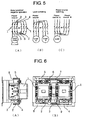
- Fig. 5 is a wiring diagram of a three-pole electromagnetic contactor using such a terminal connection device.
- Fig. 5 (A) shows the connection where two electromagnetic contactors 1 are used to perform the positive/negative operation of a motor.
- the space between terminals 1-1, the space between terminals 3-3, and the space between terminals 5-5 are bridged by the terminal connection conductors 2, 3, and 4 to be bridged in the order of phases (i.e., the same phases are bridged) and, with regards to the load side, the space between terminals 2-6, the space between terminals 4-4, and the space between terminals 6-2 are bridged by the terminal connection conductors 5, 6, and 7 to be bridged in the order in which phases are switched (i.e., to be bridged so that two phases of three phases are switched).
- Fig. 5 (B) shows that two electromagnetic contactors 1 are used to switch two loads A and B and in which the power source side is bridged in the order of phases.
- the load A is supplied from the power source and, when the right side is turned ON, then the load B is supplied from the power source.
- Fig. 5 (C) shows that two electromagnetic contactors 1 are used to switch two power sources A and B wherein the load side is bridged in the order of phases.
- the left side of Fig. 5 (C) is turned ON, the power source A supplies the load and, when the right side is turned ON, the power source B supplies the load.
- the space between the terminals at the power source side (upper side) is bridged by the terminal connection conductors 5 to 7 in the order of the switching of phases while the space between the terminals at the load side (lower side) is bridged by the terminal connection conductors 2 to 4 in the order of phases.
- Spanish Patent Publication No. ES 2 081 243 discloses a terminal connection device according to the pre-characterizing portion of claim 1.
- the insulation case is composed of an elongated base portion and a plurality of inverted-L shaped extensions projecting from a longitudinal side of the base portion. Two such extensions together with a corresponding part of the first portion define a U-shaped chamber that accommodates one of the terminal connection conductors.
- the individual chambers in the base portion are separated by partitions walls from each other.
- the device is designed such that electric insulation elements with a chamber or groove for guiding an electric wire are provided, and into each groove is inserted an electric wire for bridging between the terminals.
- the present invention intends to solve these problems. It is an objective of the present invention to improve the insulation of the terminal connection conductor, to prevent an incorrect wiring operation, and to simplify the wiring work and the management of components.
- the terminal connection conductors for a plurality of phases are collectively housed in the insulation case for unitization. This enables the insulation of the terminal connection conductors to be completely protected from the exterior. This also can adopt, since each of the terminal connection conductors can be insulation-covered in the minimum range required for interphase insulation, the minimum amount of insulation covering utilizing a thermal contraction tube, thus simplifying the insulation covering operation.
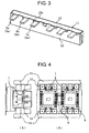
- the terminal connection conductors 2 to 7 consist of a U-shaped conductor pressed out of a plate material and both ends thereof are bent to have a right angle to provide terminal sections 2a to 7a.
- the conductor part except for the terminal sections 2a to 7a is covered by an insulation material 10 consisting of a thermal contraction tube.
- This insulation covering 10 covers, as shown in the drawing, only up to the middle of the U-bend part of the conductor for the minimum covering required to provide the interphase insulation of the terminal connection conductors 2 to 7, thus suppressing wrinkles caused at the thermal contraction.
- the terminal connection conductors 2 to 7 for a plurality of phases are collectively surrounded, except for the terminal sections 2a to 7a, by an insulation case 11 consisting of molded resin.
- the insulation case 11 consists of a box-shaped body 12 having at the upper face an opening, and a plate-shaped cover body 13 for covering the opening.
- the upper edge of the front face of the body 12 has six notches 12a engaged with the terminal sections 2a to 7a of the terminal connection conductors 2 to 7 and the center of the front face and both ends thereof have an engagement section 12b engaged with the cover body 13.
- the cover body 13 has, at the front edge thereof, six convex sections 13a engaged with the notches 12a of the body 12, and engagement nails 13b are provided to correspond to the engagement sections 12b of the body 12.
- the above-described terminal connection conductors 2 to 7 are attached by superimposing them so as to be parallel to one another in the plate thickness direction to insert them into the body 12 while engaging the terminal sections 2a to 7a with the notches 12a, after which the convex sections 13a are engaged with the notches 12a to engage the cover body 13 to the opening of the body 12, thereby engaging the engagement nails 13b with the engagement sections 12b in a snap fit manner.
- the terminal connection conductors 2 to 7 housed in the body 12 are positioned by the notches 12a via the terminal sections 2a to 7a and are pressed and fixed by the cover body 13. This allows the terminal connection conductors 2 to 7 for the respective phases to be integrally unitized via the insulation case.
- Fig. 3 shows the terminal connection device unitized in this manner.
- terminal connection conductors for a plurality of phases are collectively surrounded by the insulation case in a unitized manner. This enables the insulation to be completely protected while simplifying the insulation covering of the terminal connection conductors, and can prevent an incorrect wiring operation and improve the workability in various operations.
Landscapes
- Physics & Mathematics (AREA)
- Electromagnetism (AREA)
- Switch Cases, Indication, And Locking (AREA)
- Connections Arranged To Contact A Plurality Of Conductors (AREA)
Claims (4)
- Anschlußverbindungs-Vorrichtung eines elektrischen Apparates, bei der die Anschlußverbindungs-Vorrichtung Anschlußverbindungs-Leiter (2-7) für eine Mehrzahl von Phasen zum Überbrücken zwischen den Anschlüssen zweier elektrischer Apparate, die nebeneinander liegend vorgesehen sind, aufweist, und dieser Anschlußverbindungs-Leiter an seinen beiden Enden Anschlußabschnitte (2a-7a) zur Verbindung mit den Anschlüssen der elektrischen Apparate aufweist und aus einem U-förmigen Leiter besteht, wobei die Anschlußverbindungs-Vorrichtung ein Isoliergehäuse (11) aufweist, das die Anschlußverbindungs-Leiter (2-7) für eine Mehrzahl von Phasen, mit Ausnahme der Anschlußabschnitte (4), zusammen umgibt, und dieses Isoliergehäuse die Anschlußverbindungs-Leiter (2-7) zur Vereinigung beherbergt,
dadurch gekennzeichnet, daß
der Verbindungsteil der U-förmigen Leiter, außer den Anschlußabschnitten (2a-7a), mit einem Isoliermaterial (10) bedeckt ist. - Anschlußverbindungs-Vorrichtung gemäß Anspruch 1, dadurch gekennzeichnet, daß die Anschlußverbindungs-Leiter (2-7) bestehend aus einem Plattenmaterial so vorgesehen sind, daß sie parallel zueinander in der Plattendickenrichtung sind.
- Anschlußverbindungs-Vorrichtung gemäß Anspruch 2, dadurch gekennzeichnet, daß das Isoliergehäuse (11) aus einem kastenförmigen Körper (12) besteht, an einer oberen Seite eine Öffnung hat und an einer oberen Kante Kerben (12a) aufweist, die mit den Anschlußabschnitten (2a-7a) der Anschlußverbindungs-Leiter (2-7) in Eingriff stehen, und einen plattenförmigen Deckel (13), der an dem Körper (12) angebracht ist und mit ihm in Eingriff steht und die Öffnung bedeckt, wobei die Anschlußverbindungs-Leiter (2-7), die in den Körper (12) eingefügt sind und deren Anschlußabschnitte (2a-7a) durch die Kerben (12a) vorstehen, durch den Deckel (13) gepresst werden und durch die Kerben (12a) und die Abdeckung (13) fixiert werden.
- Anschlußverbindungs-Vorrichtung eines elektrischen Apparates gemäß Anspruch 2, dadurch gekennzeichnet, daß die Anschlußverbindungs-Leiter (2-7) durch thermische Kontraktionsröhren isoliert sind.
Applications Claiming Priority (3)
| Application Number | Priority Date | Filing Date | Title |
|---|---|---|---|
| JP2002359733 | 2002-12-11 | ||
| JP2002359733 | 2002-12-11 | ||
| PCT/JP2003/010639 WO2004053912A1 (ja) | 2002-12-11 | 2003-08-22 | 電気機器の端子接続装置 |
Publications (3)
| Publication Number | Publication Date |
|---|---|
| EP1583126A1 EP1583126A1 (de) | 2005-10-05 |
| EP1583126A4 EP1583126A4 (de) | 2006-10-04 |
| EP1583126B1 true EP1583126B1 (de) | 2008-09-17 |
Family
ID=32500952
Family Applications (1)
| Application Number | Title | Priority Date | Filing Date |
|---|---|---|---|
| EP03812674A Expired - Lifetime EP1583126B1 (de) | 2002-12-11 | 2003-08-22 | Anschlussverbinder für elektronische geräte |
Country Status (9)
| Country | Link |
|---|---|
| US (1) | US7189108B2 (de) |
| EP (1) | EP1583126B1 (de) |
| JP (1) | JP4106631B2 (de) |
| KR (1) | KR100910101B1 (de) |
| CN (1) | CN100346437C (de) |
| AU (1) | AU2003257662A1 (de) |
| DE (1) | DE60323679D1 (de) |
| TW (1) | TWI267243B (de) |
| WO (1) | WO2004053912A1 (de) |
Families Citing this family (16)
| Publication number | Priority date | Publication date | Assignee | Title |
|---|---|---|---|---|
| US7268446B2 (en) * | 2004-09-01 | 2007-09-11 | Yazaki North America, Inc. | Power control center with solid state device for controlling power transmission |
| US7268447B2 (en) * | 2004-09-01 | 2007-09-11 | Yazaki North America, Inc. | Power control center with solid state device for controlling power transmission |
| CN101752762B (zh) * | 2008-12-04 | 2012-10-10 | 鸿富锦精密工业(深圳)有限公司 | 跳帽 |
| JP5612831B2 (ja) * | 2009-05-20 | 2014-10-22 | モレックス インコーポレイテドMolex Incorporated | ループコネクタ及び閉回路形成コネクタ |
| US8339760B2 (en) * | 2009-06-15 | 2012-12-25 | Apple Inc. | Thermal protection circuits and structures for electronic devices and cables |
| US8498087B2 (en) * | 2009-11-03 | 2013-07-30 | Apple Inc. | Thermal protection circuits for electronic device cables |
| US8824162B2 (en) | 2010-08-30 | 2014-09-02 | Apple Inc. | Electronic devices with moisture guiding structures |
| US9237401B2 (en) | 2010-08-31 | 2016-01-12 | Apple Inc. | Electronic devices with adjustable bias impedances and adjustable bias voltages for accessories |
| EP2444989A1 (de) * | 2010-10-20 | 2012-04-25 | Ghisalba S.P.A. | Elektromechanische Schaltkomponente mit elektromagnetischer Steuerung für stromerzeugende Einheiten oder Notstromgeneratoren |
| CN102593661B (zh) * | 2011-01-14 | 2014-07-02 | 富士康(昆山)电脑接插件有限公司 | 电连接器 |
| CN102683114B (zh) * | 2011-03-18 | 2015-02-18 | Ls产电株式会社 | 接线套件 |
| FR2983647B1 (fr) * | 2011-12-06 | 2013-12-27 | Schneider Electric Ind Sas | Conducteurs de courant pour inverseur |
| FR2999780A1 (fr) * | 2012-12-18 | 2014-06-20 | Schneider Electric Ind Sas | Dispositif modulaire de commutation electrique comportant au moins un bloc de coupure unipolaire et ensemble de commutation comportant de tels dispositifs. |
| CN103700546A (zh) * | 2013-12-25 | 2014-04-02 | 施耐德万高(天津)电气设备有限公司 | 低压断路器用换相块 |
| JP6576233B2 (ja) * | 2015-12-16 | 2019-09-18 | 日東工業株式会社 | 導電部の保護構造 |
| ES3046544A1 (es) * | 2024-05-31 | 2025-12-02 | Gilabert Juan Carlos Tomas | Sistema de conexion para modulos de proteccion de distribucion electrica |
Family Cites Families (16)
| Publication number | Priority date | Publication date | Assignee | Title |
|---|---|---|---|---|
| DE1959962U (de) * | 1967-01-24 | 1967-05-11 | Elektrotechnische Fabrik Kuepp | Schaltgeraetebank mit kontaktbruecken. |
| NL6817197A (de) | 1968-11-30 | 1970-06-02 | ||
| JPS5922736Y2 (ja) * | 1977-02-23 | 1984-07-06 | 富士通株式会社 | 電源バスバ− |
| DE2912944A1 (de) * | 1979-03-31 | 1980-10-16 | Bbc Brown Boveri & Cie | Sammelschienenblock |
| AT366854B (de) * | 1979-05-18 | 1982-05-10 | Bbc Brown Boveri & Cie | Stromschienenanordnung fuer installationsteile |
| JPS575829Y2 (de) | 1981-01-16 | 1982-02-03 | ||
| JPS5922736A (ja) | 1982-07-30 | 1984-02-06 | Sekisui Chem Co Ltd | 空調用配管保護カバ−の製造方法 |
| FR2647272A1 (fr) * | 1989-05-16 | 1990-11-23 | Faveresse Patrick | Barres de pontage pour prises de courant modulaires |
| FR2664755B1 (fr) * | 1990-07-16 | 1994-10-21 | Schrack Components Ag | Systeme de rails de raccordement. |
| ES2081243B1 (es) * | 1993-01-20 | 1997-07-01 | Vega Y Farres S A | Bloque de conexion para contactores electricos. |
| JPH08251781A (ja) * | 1995-03-07 | 1996-09-27 | Kyodo Ky Tec Kk | 帯板導体電路の分岐装置 |
| JPH08251779A (ja) * | 1995-03-14 | 1996-09-27 | Kyodo Ky Tec Kk | 分岐部用帯板導体および帯板導体電路の分岐装置 |
| JP3255097B2 (ja) | 1997-10-16 | 2002-02-12 | 住友電装株式会社 | 電気接続箱 |
| KR20000019177U (ko) * | 1999-04-06 | 2000-11-06 | 오병남 | 단자블록 |
| CN2416596Y (zh) * | 2000-01-05 | 2001-01-24 | 长沙丰日电气集团有限公司 | 交流接触器插接联接器 |
| ES2199030B1 (es) * | 2001-09-07 | 2005-05-01 | Ge Power Controls Iberica, S.L. | Sistema de conexion electrica entre modulos para la proteccion de circuitos de distribucion electrica. |
-
2003
- 2003-07-31 TW TW092121026A patent/TWI267243B/zh not_active IP Right Cessation
- 2003-08-22 EP EP03812674A patent/EP1583126B1/de not_active Expired - Lifetime
- 2003-08-22 JP JP2004558391A patent/JP4106631B2/ja not_active Expired - Fee Related
- 2003-08-22 CN CNB038256150A patent/CN100346437C/zh not_active Expired - Fee Related
- 2003-08-22 AU AU2003257662A patent/AU2003257662A1/en not_active Abandoned
- 2003-08-22 KR KR1020057010111A patent/KR100910101B1/ko not_active Expired - Fee Related
- 2003-08-22 DE DE60323679T patent/DE60323679D1/de not_active Expired - Lifetime
- 2003-08-22 US US10/538,917 patent/US7189108B2/en not_active Expired - Fee Related
- 2003-08-22 WO PCT/JP2003/010639 patent/WO2004053912A1/ja not_active Ceased
Also Published As
| Publication number | Publication date |
|---|---|
| AU2003257662A1 (en) | 2004-06-30 |
| WO2004053912A1 (ja) | 2004-06-24 |
| CN100346437C (zh) | 2007-10-31 |
| JP4106631B2 (ja) | 2008-06-25 |
| EP1583126A4 (de) | 2006-10-04 |
| KR100910101B1 (ko) | 2009-07-30 |
| TWI267243B (en) | 2006-11-21 |
| JPWO2004053912A1 (ja) | 2006-04-13 |
| EP1583126A1 (de) | 2005-10-05 |
| KR20050085353A (ko) | 2005-08-29 |
| CN1714418A (zh) | 2005-12-28 |
| DE60323679D1 (de) | 2008-10-30 |
| US20060211299A1 (en) | 2006-09-21 |
| US7189108B2 (en) | 2007-03-13 |
| TW200410459A (en) | 2004-06-16 |
Similar Documents
| Publication | Publication Date | Title |
|---|---|---|
| EP1583126B1 (de) | Anschlussverbinder für elektronische geräte | |
| EP1130616B1 (de) | Sicherung und Sicherungshalter | |
| EP2128942B1 (de) | Modulares Bussystem und Modulkörper zur Verwendung darin | |
| US6285271B1 (en) | Capacitor switching contactor | |
| EP2515318B1 (de) | Kompakte Busschienenanordnung, Schaltvorrichtung und Energieverteilungssystem | |
| US9136083B2 (en) | Enclosed bus bar fuse holder | |
| US5933066A (en) | Circuit interrupter with terminal shield and wire trough | |
| KR20190047069A (ko) | 접촉 링, 고정자 및 전기 모터 | |
| JP2006256448A (ja) | 自動車用コネクタ組立体 | |
| JP6599404B2 (ja) | クランプ及びバスバーモジュール | |
| KR20040002676A (ko) | 전자기적 보호 및 제어 어셈블리 | |
| JP6623833B2 (ja) | 配線モジュール | |
| EP1139531A2 (de) | Stromversorgungsanordnung | |
| EP1130683A1 (de) | Energieverteileranordnung | |
| RU2256987C2 (ru) | Контактное устройство для разъемного соединения подвижного приборного блока с неподвижными контактными телами | |
| JP2008029133A (ja) | 分電盤 | |
| EP0757367A1 (de) | Schaltsystem mit Anschlussklemmenmodulen | |
| WO2011155369A1 (ja) | 電池接続プレート | |
| EP3843199A1 (de) | Sammelschienenmodul | |
| JP4676663B2 (ja) | 住宅用分電盤 | |
| JP3414259B2 (ja) | 接続変換アダプタ | |
| JP2000340275A (ja) | 保護継電器 | |
| JP2003086321A (ja) | ケーブルリール | |
| JP2024027390A (ja) | ヒューズユニットおよびヒューズユニット組み立て方法 | |
| EP1548786B1 (de) | Sicherungsanschlussanordnung für Stromschiene und elektrisches Verbindungsgehäuse mit einer solchen Anordnung |
Legal Events
| Date | Code | Title | Description |
|---|---|---|---|
| PUAI | Public reference made under article 153(3) epc to a published international application that has entered the european phase |
Free format text: ORIGINAL CODE: 0009012 |
|
| 17P | Request for examination filed |
Effective date: 20050706 |
|
| AK | Designated contracting states |
Kind code of ref document: A1 Designated state(s): AT BE BG CH CY CZ DE DK EE ES FI FR GB GR HU IE IT LI LU MC NL PT RO SE SI SK TR |
|
| AX | Request for extension of the european patent |
Extension state: AL LT LV MK |
|
| RAP1 | Party data changed (applicant data changed or rights of an application transferred) |
Owner name: FUJI ELECTRIC FA COMPONENTS & SYSTEMS CO., LTD |
|
| DAX | Request for extension of the european patent (deleted) | ||
| RBV | Designated contracting states (corrected) |
Designated state(s): DE FR IT |
|
| A4 | Supplementary search report drawn up and despatched |
Effective date: 20060906 |
|
| 17Q | First examination report despatched |
Effective date: 20070425 |
|
| GRAP | Despatch of communication of intention to grant a patent |
Free format text: ORIGINAL CODE: EPIDOSNIGR1 |
|
| GRAS | Grant fee paid |
Free format text: ORIGINAL CODE: EPIDOSNIGR3 |
|
| GRAA | (expected) grant |
Free format text: ORIGINAL CODE: 0009210 |
|
| AK | Designated contracting states |
Kind code of ref document: B1 Designated state(s): DE FR IT |
|
| REF | Corresponds to: |
Ref document number: 60323679 Country of ref document: DE Date of ref document: 20081030 Kind code of ref document: P |
|
| PLBE | No opposition filed within time limit |
Free format text: ORIGINAL CODE: 0009261 |
|
| STAA | Information on the status of an ep patent application or granted ep patent |
Free format text: STATUS: NO OPPOSITION FILED WITHIN TIME LIMIT |
|
| 26N | No opposition filed |
Effective date: 20090618 |
|
| REG | Reference to a national code |
Ref country code: FR Ref legal event code: TP |
|
| REG | Reference to a national code |
Ref country code: DE Ref legal event code: R084 Ref document number: 60323679 Country of ref document: DE Effective date: 20130423 |
|
| PGFP | Annual fee paid to national office [announced via postgrant information from national office to epo] |
Ref country code: IT Payment date: 20130809 Year of fee payment: 11 |
|
| PG25 | Lapsed in a contracting state [announced via postgrant information from national office to epo] |
Ref country code: IT Free format text: LAPSE BECAUSE OF NON-PAYMENT OF DUE FEES Effective date: 20140822 |
|
| PGFP | Annual fee paid to national office [announced via postgrant information from national office to epo] |
Ref country code: DE Payment date: 20150818 Year of fee payment: 13 |
|
| REG | Reference to a national code |
Ref country code: FR Ref legal event code: PLFP Year of fee payment: 14 |
|
| REG | Reference to a national code |
Ref country code: DE Ref legal event code: R119 Ref document number: 60323679 Country of ref document: DE |
|
| REG | Reference to a national code |
Ref country code: FR Ref legal event code: PLFP Year of fee payment: 15 |
|
| PG25 | Lapsed in a contracting state [announced via postgrant information from national office to epo] |
Ref country code: DE Free format text: LAPSE BECAUSE OF NON-PAYMENT OF DUE FEES Effective date: 20170301 |
|
| PGFP | Annual fee paid to national office [announced via postgrant information from national office to epo] |
Ref country code: FR Payment date: 20170714 Year of fee payment: 15 |
|
| PG25 | Lapsed in a contracting state [announced via postgrant information from national office to epo] |
Ref country code: FR Free format text: LAPSE BECAUSE OF NON-PAYMENT OF DUE FEES Effective date: 20180831 |