EP1582252A1 - Hochwirksamer Kleinstoffaustauschapparat mit Hohlfasermembranen und drei Zu- und Ableitungen - Google Patents
Hochwirksamer Kleinstoffaustauschapparat mit Hohlfasermembranen und drei Zu- und Ableitungen Download PDFInfo
- Publication number
- EP1582252A1 EP1582252A1 EP20050006520 EP05006520A EP1582252A1 EP 1582252 A1 EP1582252 A1 EP 1582252A1 EP 20050006520 EP20050006520 EP 20050006520 EP 05006520 A EP05006520 A EP 05006520A EP 1582252 A1 EP1582252 A1 EP 1582252A1
- Authority
- EP
- European Patent Office
- Prior art keywords
- hollow fiber
- end cap
- tube
- opening
- tube sheet
- Prior art date
- Legal status (The legal status is an assumption and is not a legal conclusion. Google has not performed a legal analysis and makes no representation as to the accuracy of the status listed.)
- Granted
Links
- 239000012510 hollow fiber Substances 0.000 title claims abstract description 122
- 239000012528 membrane Substances 0.000 title claims abstract description 58
- 239000004744 fabric Substances 0.000 claims abstract description 62
- 238000004891 communication Methods 0.000 claims abstract description 20
- 239000000463 material Substances 0.000 claims description 32
- 239000012530 fluid Substances 0.000 claims description 22
- 239000007788 liquid Substances 0.000 claims description 20
- -1 polyethylene Polymers 0.000 claims description 20
- 239000004698 Polyethylene Substances 0.000 claims description 14
- 229920000573 polyethylene Polymers 0.000 claims description 14
- 239000000835 fiber Substances 0.000 claims description 5
- 238000007872 degassing Methods 0.000 claims description 2
- 238000004382 potting Methods 0.000 description 34
- 238000000034 method Methods 0.000 description 12
- 239000007789 gas Substances 0.000 description 11
- 239000012466 permeate Substances 0.000 description 6
- 238000009792 diffusion process Methods 0.000 description 4
- 229920000098 polyolefin Polymers 0.000 description 4
- 229920001187 thermosetting polymer Polymers 0.000 description 4
- 238000003466 welding Methods 0.000 description 4
- 239000004743 Polypropylene Substances 0.000 description 3
- 229920001155 polypropylene Polymers 0.000 description 3
- 125000006850 spacer group Chemical group 0.000 description 3
- 239000012815 thermoplastic material Substances 0.000 description 3
- IJGRMHOSHXDMSA-UHFFFAOYSA-N Atomic nitrogen Chemical compound N#N IJGRMHOSHXDMSA-UHFFFAOYSA-N 0.000 description 2
- CURLTUGMZLYLDI-UHFFFAOYSA-N Carbon dioxide Chemical compound O=C=O CURLTUGMZLYLDI-UHFFFAOYSA-N 0.000 description 2
- 239000004593 Epoxy Substances 0.000 description 2
- 239000011324 bead Substances 0.000 description 2
- 229920002678 cellulose Polymers 0.000 description 2
- 239000001913 cellulose Substances 0.000 description 2
- 238000010276 construction Methods 0.000 description 2
- 230000005484 gravity Effects 0.000 description 2
- 229910052500 inorganic mineral Inorganic materials 0.000 description 2
- 150000002500 ions Chemical class 0.000 description 2
- 239000011707 mineral Substances 0.000 description 2
- 229920003229 poly(methyl methacrylate) Polymers 0.000 description 2
- 239000004926 polymethyl methacrylate Substances 0.000 description 2
- 238000001223 reverse osmosis Methods 0.000 description 2
- 239000000126 substance Substances 0.000 description 2
- 229920001059 synthetic polymer Polymers 0.000 description 2
- 229920001169 thermoplastic Polymers 0.000 description 2
- 239000004416 thermosoftening plastic Substances 0.000 description 2
- 239000004925 Acrylic resin Substances 0.000 description 1
- 229920000178 Acrylic resin Polymers 0.000 description 1
- 229920000219 Ethylene vinyl alcohol Polymers 0.000 description 1
- 229920001730 Moisture cure polyurethane Polymers 0.000 description 1
- 239000004952 Polyamide Substances 0.000 description 1
- 239000004695 Polyether sulfone Substances 0.000 description 1
- 239000004697 Polyetherimide Substances 0.000 description 1
- 229920002367 Polyisobutene Polymers 0.000 description 1
- 239000004793 Polystyrene Substances 0.000 description 1
- QVGXLLKOCUKJST-UHFFFAOYSA-N atomic oxygen Chemical compound [O] QVGXLLKOCUKJST-UHFFFAOYSA-N 0.000 description 1
- 229910002092 carbon dioxide Inorganic materials 0.000 description 1
- 239000001569 carbon dioxide Substances 0.000 description 1
- 238000009826 distribution Methods 0.000 description 1
- 125000003700 epoxy group Chemical group 0.000 description 1
- 239000004715 ethylene vinyl alcohol Substances 0.000 description 1
- 229920002313 fluoropolymer Polymers 0.000 description 1
- 230000004927 fusion Effects 0.000 description 1
- RZXDTJIXPSCHCI-UHFFFAOYSA-N hexa-1,5-diene-2,5-diol Chemical compound OC(=C)CCC(O)=C RZXDTJIXPSCHCI-UHFFFAOYSA-N 0.000 description 1
- 238000005304 joining Methods 0.000 description 1
- 238000004519 manufacturing process Methods 0.000 description 1
- 239000000203 mixture Substances 0.000 description 1
- 229910052757 nitrogen Inorganic materials 0.000 description 1
- 229920001778 nylon Polymers 0.000 description 1
- 239000001301 oxygen Substances 0.000 description 1
- 229910052760 oxygen Inorganic materials 0.000 description 1
- 238000005192 partition Methods 0.000 description 1
- 229920002492 poly(sulfone) Polymers 0.000 description 1
- 229920002647 polyamide Polymers 0.000 description 1
- 229920001748 polybutylene Polymers 0.000 description 1
- 229920000647 polyepoxide Polymers 0.000 description 1
- 229920000728 polyester Polymers 0.000 description 1
- 229920006393 polyether sulfone Polymers 0.000 description 1
- 229920001601 polyetherimide Polymers 0.000 description 1
- 229920000642 polymer Polymers 0.000 description 1
- 229920000306 polymethylpentene Polymers 0.000 description 1
- 229920002223 polystyrene Polymers 0.000 description 1
- 229920002635 polyurethane Polymers 0.000 description 1
- 239000004814 polyurethane Substances 0.000 description 1
- 239000004800 polyvinyl chloride Substances 0.000 description 1
- 229920000915 polyvinyl chloride Polymers 0.000 description 1
- 230000000717 retained effect Effects 0.000 description 1
- 239000002904 solvent Substances 0.000 description 1
- 238000004804 winding Methods 0.000 description 1
Images


Classifications
-
- B—PERFORMING OPERATIONS; TRANSPORTING
- B01—PHYSICAL OR CHEMICAL PROCESSES OR APPARATUS IN GENERAL
- B01D—SEPARATION
- B01D19/00—Degasification of liquids
- B01D19/0031—Degasification of liquids by filtration
-
- B—PERFORMING OPERATIONS; TRANSPORTING
- B01—PHYSICAL OR CHEMICAL PROCESSES OR APPARATUS IN GENERAL
- B01D—SEPARATION
- B01D53/00—Separation of gases or vapours; Recovering vapours of volatile solvents from gases; Chemical or biological purification of waste gases, e.g. engine exhaust gases, smoke, fumes, flue gases, aerosols
- B01D53/22—Separation of gases or vapours; Recovering vapours of volatile solvents from gases; Chemical or biological purification of waste gases, e.g. engine exhaust gases, smoke, fumes, flue gases, aerosols by diffusion
-
- B—PERFORMING OPERATIONS; TRANSPORTING
- B01—PHYSICAL OR CHEMICAL PROCESSES OR APPARATUS IN GENERAL
- B01D—SEPARATION
- B01D63/00—Apparatus in general for separation processes using semi-permeable membranes
- B01D63/02—Hollow fibre modules
- B01D63/024—Hollow fibre modules with a single potted end
-
- B—PERFORMING OPERATIONS; TRANSPORTING
- B01—PHYSICAL OR CHEMICAL PROCESSES OR APPARATUS IN GENERAL
- B01D—SEPARATION
- B01D63/00—Apparatus in general for separation processes using semi-permeable membranes
- B01D63/02—Hollow fibre modules
- B01D63/026—Wafer type modules or flat-surface type modules
-
- B—PERFORMING OPERATIONS; TRANSPORTING
- B01—PHYSICAL OR CHEMICAL PROCESSES OR APPARATUS IN GENERAL
- B01D—SEPARATION
- B01D63/00—Apparatus in general for separation processes using semi-permeable membranes
- B01D63/02—Hollow fibre modules
- B01D63/032—More than two tube sheets for one bundle
-
- B—PERFORMING OPERATIONS; TRANSPORTING
- B01—PHYSICAL OR CHEMICAL PROCESSES OR APPARATUS IN GENERAL
- B01D—SEPARATION
- B01D2313/00—Details relating to membrane modules or apparatus
- B01D2313/44—Cartridge types
Definitions
- the instant invention relates to a three-port high performance mini hollow fiber membrane contactor.
- Liquids as used in some industries, are required to be ultrapure. These ultrapure liquids are free or substantially free from: minerals, ions, and gas. The removal of minerals and ions is most often accomplished through a reverse osmosis process. The reverse osmosis process, however, does not remove the dissolved or entrained gases. The most common dissolved or entrained gas is air, which has as its major components nitrogen, oxygen, and carbon dioxide.
- Hollow fiber membrane contactors for example, hollow fiber membrane contactors have been used to remove or add dissolved or entrained gases from or to a fluid.
- Hollow fiber membrane contactors are known. For example, see U.S. Pat. Nos. 3,288,877; 3,755,034; 4,220,535; 4,664,681; 4,940,617; 5,186,832; 5,264,171; 5,284,584; 5,352,361; and 5,449,457.
- Hollow fiber membrane contactors are commercially available under the name of LIQUI-CEL® from Membrana a division of Celgard Inc. of Charlotte, N.C. and under the name of SEPAREL® from Dainippon Ink and Chemicals of Tokyo, Japan.
- Some contactors are assembled from several pieces that are sealed with a plurality of O-rings, and then, they are mechanically fastened (e.g. clamped) together.
- Such contactors have numerous uses, one being the degassing of liquids.
- the hollow fiber membranes are typically formed into a fabric (e.g., woven or knitted).
- the fabric is wound around a mandrel (e.g., a perforated center tube) and fixed into place by potting the fabric edges, with either thermosetting or thermoplastic materials, to form a unitized structure.
- a mandrel e.g., a perforated center tube
- This unit can then be inserted within a shell (housing) and sealed, i.e., with or without O-rings, to make a membrane contactor. See, for example, U.S. Pat. No. 6,207,053.
- the instant invention is a three-port high performance mini hollow fiber membrane contactor.
- the hollow fiber membrane contactor includes a cartridge, a shell, a first end cap, and a second end cap.
- the shell encloses the cartridge, and it has two ends and an opening.
- the cartridge further includes a perforated center tube, a hollow fiber fabric, a first tube sheet, a second tube sheet, and a plug.
- the perforated center tube has a first end and a second end, and the hollow fiber fabric surrounds the center tube.
- the hollow fiber fabric includes hollow fiber membranes, and each hollow fiber membrane has a lumen.
- a first tube sheet and a second tube sheet affixes said fabric to said center tube at each end of the center tube, and the plug is located at the first tube sheet.
- Hollow fiber lumens are open at the first tube sheet and hollow fiber lumens are closed at the second tube sheet.
- the first end cap and the first tube sheet define a first headspace therebetween.
- the first end cap has an opening therethrough, which is in communication with hollow fiber lumens via said first headspace.
- the second end cap has an opening, and it is in communication with the center tube.
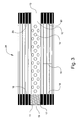
- FIG. 1 a preferred embodiment of a hollow fiber membrane contactor 10 according to instant invention.
- Contactor 10 includes a shell 22, a cartridge 24, first end cap 26, and second end cap 28.
- Cartridge 24 includes a perforated center tube 12, a hollow fiber fabric 16, a first tube sheet 18, a second tube sheet 20, and a plug 15.
- Shell 22 encloses cartridge 24, and first end cap 26 and second end cap 28 are affixed to shell 22 at first shell end 21, and second shell end 23, as shown in fig. 2, respectively.
- a liquid for example laden with entrained gas
- a liquid is introduced to hollow fiber contactor 10 via port 34, which is in fluid communication with center tube 12 via second headspace 32.
- the liquid exits center tube 12 via perforations 14, travels over the exterior surface of the hollow fiber membranes of the hollow fiber fabric 16, and exits contactor 10 via port 36.
- Port 38 which is in fluid communication with lumen side of hollow fibers of fabric 16 via first headspace 30, is coupled with a vacuum source. Therefore, when the gas-laden liquid travels over the exterior surface of the hollow fibers of fabric 16, vacuum drawn in the lumen side of the hollow fibers of fabric 16 provides the driving force for the diffusion of the gas from the liquid to the lumen side of the hollow fibers of fabric 16 where it is exhausted via port 38.
- a liquid for example laden with entrained gas is introduced, under elevated pressure, to hollow fiber contactor 10 via port 34, which is in fluid communication with center tube 12 via second headspace 32.
- the liquid which is under elevated pressure, exits center tube 12 via perforations 14, travels over the exterior surface of the hollow fiber membranes of the hollow fiber fabric 16, and exits contactor 10 via port 36.
- Port 38 is in fluid communication with lumen side of hollow fibers of fabric 16 via first headspace 30, which is maintained at ambient pressure.
- the ambient pressure maintained in the lumen side of the hollow fibers of fabric 16 and the elevated pressure forced upon the exterior surface of the hollow fibers of fabric 16 provide the driving force for the diffusion of the gas from the liquid to the lumen side of the hollow fibers of fabric 16 where it is exhausted via port 38.
- a liquid is introduced to hollow fiber contactor 10 via port 34, which is in fluid communication with center tube 12 via second headspace 32.
- the liquid exits center tube 12 via perforations 14, travels over the exterior surface of the hollow fiber membranes of the hollow fiber fabric 16, and exits contactor 10 via port 36.
- a gas is introduced, under elevated pressure, into the lumen side of hollow fibers of fabric 16 via Port 38. Therefore, when the liquid travels over the exterior surface of the hollow fibers of fabric 16, the elevated gas pressure maintained in the lumen side of the hollow fibers of fabric 16 provides the driving force for the diffusion of the gas from the lumen side of the hollow fibers of fabric 16 into the liquid, which is exits the contactor 10 via Port 36.
- shell 22 has a port 36, described hereinbelow in detail, a first shell end 21, and a second shell end 23.
- Shell 22 may be made of any material, and preferably, shell 22 is made of polyethylene.
- Shell 22 may have any shape. Such shapes may be selected from the group consisting of a cylindrical shape, a rectangular shape, and combinations thereof.
- Shell 22 may or may not have flanged ends on either side.
- Shell 22 may have any diameter.
- shell 22 has a diameter of 4 inches or less.
- Shell 22 may have any length, and preferably, shell 22 has a length of 24 inches or less.
- cartridge 24 includes a perforated center tube 12, a hollow fiber fabric 16, a first tube sheet 18, a second tube sheet 20, and a plug 15.
- Center tube 12 may be made of any material, which possesses sufficient mechanical strength to provide the desired support for the hollow fiber fabric 16, first tube sheet 18, and second tube sheet 20.
- center tube 12 is made of polyethylene.
- Center tube 12 may include plurality of perforations 14, and a flow-diverting baffle.
- Center tube 12 may posses a channel, preferably, center tube 12 has a first tube end 11 and a second tube end 13, and most preferably, first tube end 11 is closed.
- the first tube end 11 may contain internal grooves 17.
- Hollow fiber fabric 16 may be constructed using processes well known in the art. Generally, in hollow fiber fabric construction, the hollow fiber membranes are formed into a bundle with a suitable shape for hollow fiber fabric construction. Preferred bundle arrangements include parallel laying down of fibers or bias wrap laying down of fibers. The hollow fibers of hollow fiber fabric 16 are any membranes suitable for use in diffusion operations. See Kesting, R. E., Synthetic Polymeric Membranes, 2 nd ed., John Wiley & Sons, New York, N.Y., (1985), incorporated herein by reference.
- the hollow fiber membranes may be made of synthetic polymers, cellulose, or synthetically modified cellulose.
- Synthetic polymers include, but are not limited to, polyethylene, polypropylene, polybutylene, poly (isobutylene), poly (methyl pentene), polysulfone, polyethersulfone, polyester, polyetherimide, polyacryinitril, polyamide, polymethylmethacrylate (PMMA), ethylenevinyl alcohol, and fluorinated polyolefins.
- the hollow fiber membranes are made of polyolefins. Examples include, but are not limited to, microporous polyolefin membranes, commercially available under the name of CELGARD® hollow fibers from Celgard Inc. of Charlotte, N.C. or membranes from Dainippon Ink and Chemicals of Tokyo, Japan, see U.S. Pat. No. 4,664,681 incorporated herein by reference.
- Spacer may be used to maintain the space between the layers of the wound hollow fiber fabric 16, so that fluid may be evenly distributed over the entire surface of all the hollow fibers. This distribution is important to maximize removal efficiency of the contactor. See U.S. Pat. No. 4,940,617. Spacer may be made of any material, preferably, spacer is made of polyethylene.
- First tube sheet 18 is located at one end of hollow fiber fabric 16 near the first tube end 11 while second tube sheet 20 is located at the other end of hollow fabric 16 near the second tube end 13.
- first tube sheet 18 and second tube sheet 20 are cylindrical in longitudinal cross section with sufficient thickness to provide support for the hollow fiber fabric 16 and to withstand the pressure exerted on them during operation.
- First tube sheet 18 and second tube sheet 20 function to hold the hollow fiber fabric 16 in place, and to partition the contactor 10 into a shell side passageway and a lumen side passageway.
- First tube sheet 18 and second tube sheet 20 may be comprised of an integral potting material. Integral potting material may be any material.
- integral potting material is polyethylene.
- Plug 15 functions to seal off first tube end 11.
- Plug 15 may be made of any material; preferably, plug 15 is made of polyethylene.
- Plug 15 may be any shape; preferably, plug 15 may be cylindrical in longitudinal cross section with sufficient thickness to withstand the pressure exerted on it during operation.
- Plug 15 may have grooves, which are complimentary to the grooves 17, to secure plug 15 to center tube 12.
- plug 15 may be an integral component of center tube 12, or it may be an integral component of first tube sheet 18.
- hollow fiber fabric 16 is wrapped around center tube 12, and simultaneously, a sufficient amount of external potting material, i.e. polyethylene, is laid at the lateral edges of fabric 16 to secure fabric 16 to center tube 12, and thereby forming a fabric-tube assembly.
- This fabric-tube assembly is, then, placed within shell 22, and an integral potting material is applied to the lateral ends of the fabric-tube assembly to form first tube sheet 18 and second tube sheet 20 thereby forming cartridge 24, and simultaneously forming a seal therebetween cartridge 24 and shell 22; thus forming a cartridge-shell assembly 25.
- External potting materials may be thermosetting materials or thermoplastic materials.
- Thermosetting materials include, but are not limited to, epoxy, and polyurethane. Epoxies are preferred.
- Thermoplastics refers to a high polymer that softens when exposed to heat and returns to its original condition when cooled to room temperature; the term is usually applied to synthetics such as polyvinyl chloride, nylons, fluorocarbon polymers, polyethylene, polyurethane prepolymer, polystyrene, polypropylene, and cellulosic and acrylic resins.
- Exemplary thermoplastics include polyolefins, such as polypropylene and polyethylene.
- external potting materials are polyethylene.
- the external potting step is achieved via bead potting.
- Integral potting materials may be thermosetting materials or thermoplastic materials, as described hereinabove. Integral potting materials may be the same material as the first potting material, as described hereinabove. Preferably, integral potting materials are polyethylene.
- Different potting methods may be employed to complete the integral potting step.
- Different potting methods include, but are not limited to, centrifugal potting, mold potting, and gravity potting.
- the fabric-tube-assembly is inserted into shell 22, the assembly is then spun on its midpoint to create centrifugal force at both ends of the fabric-tube-assembly, integral potting material are introduced into the shell-side space near both ends of the fabric-tube-assembly, and the integral potting material is allowed to cure.
- the integral potting material is introduced into each end of the vertically mounted fabric-tube-assembly, one at a time, and allowed to settle into the end of the fabric-tube-assembly and cure.
- the fabric-tube-assembly In mold potting, the fabric-tube-assembly is placed in a mold, and the mold is filled with the integral potting material to a desired depth. The fabric-tube-assembly is retained in filled mold until integral potting material hardens.
- End caps 26 and 28 are adjoined to cartridge-shell assembly 25 to form contactor (10).
- End caps 26 and 28 may be made of any material; preferably, end caps 26 and 28 are made of polyethylene.
- the adjoining of the end caps 26 and 28 to the cartridge (21) can be achieved by various techniques such as heat welding technique, heat fusion technique, solvent welding technique, ultrasonic welding technique, and infrared welding technique.
- Membrane contactor 10 may have any number of ports, preferably, contactor 10 has three ports: port 34, port 36, and port 38. As will be readily apparent to those of ordinary skill, placement of ports may vary, so long as the integrity of the shell side passageway and the lumen side passageway according to instant invention is maintained.
- Port 34 is a feed inlet means; it is generally a port, nozzle, fitting or other opening which allows introduction of fluid mixtures, which are to be separated, into a hollow fiber membrane contactor.
- Port 36 is a non-permeate outlet means, which is adapted for removing the fluids, which do not permeate through the hollow fiber membranes.
- Port 36 is generally a port, nozzle, fitting, or other opening, which allows the removal of the non-permeate from the hollow fiber membrane contactor.
- Port 38 may be a permeate outlet means for removing fluid, which permeate through the hollow fiber membrane, or the means for introducing fluid at elevated pressure into the lumen side of hollow fiber fabric 16.
- Port 38 is generally a port, nozzle, fitting, or other opening adapted for withdrawing the permeate or introducing a fluid.
Landscapes
- Chemical & Material Sciences (AREA)
- Chemical Kinetics & Catalysis (AREA)
- Engineering & Computer Science (AREA)
- Analytical Chemistry (AREA)
- General Chemical & Material Sciences (AREA)
- Oil, Petroleum & Natural Gas (AREA)
- Separation Using Semi-Permeable Membranes (AREA)
- Degasification And Air Bubble Elimination (AREA)
Applications Claiming Priority (2)
| Application Number | Priority Date | Filing Date | Title |
|---|---|---|---|
| US812450 | 1997-03-06 | ||
| US10/812,450 US7638049B2 (en) | 2004-03-30 | 2004-03-30 | Three-port high performance mini hollow fiber membrane contactor |
Publications (3)
| Publication Number | Publication Date |
|---|---|
| EP1582252A1 true EP1582252A1 (de) | 2005-10-05 |
| EP1582252B1 EP1582252B1 (de) | 2015-12-30 |
| EP1582252B8 EP1582252B8 (de) | 2016-04-20 |
Family
ID=34887681
Family Applications (1)
| Application Number | Title | Priority Date | Filing Date |
|---|---|---|---|
| EP05006520.0A Expired - Lifetime EP1582252B8 (de) | 2004-03-30 | 2005-03-24 | Hochwirksamer Kleinstoffaustauschapparat mit Hohlfasermembranen und drei Zu- und Ableitungen |
Country Status (5)
| Country | Link |
|---|---|
| US (1) | US7638049B2 (de) |
| EP (1) | EP1582252B8 (de) |
| JP (1) | JP4034318B2 (de) |
| CN (1) | CN1326596C (de) |
| TW (1) | TWI250891B (de) |
Cited By (3)
| Publication number | Priority date | Publication date | Assignee | Title |
|---|---|---|---|---|
| WO2011012995A3 (de) * | 2009-07-31 | 2011-05-19 | Alex Knobel | Vorrichtung und verfahren zum mischen und austauschen von fluiden |
| EP2755746A4 (de) * | 2011-09-12 | 2016-03-09 | 3M Innovative Properties Co | Verbesserte schütze, kassetten, komponenten, systeme und zugehörige verfahren |
| EP3434350A1 (de) * | 2017-07-25 | 2019-01-30 | Hamilton Sundstrand Corporation | Flüssigkeitsentgasungssysteme |
Families Citing this family (31)
| Publication number | Priority date | Publication date | Assignee | Title |
|---|---|---|---|---|
| US7682421B2 (en) * | 2006-10-12 | 2010-03-23 | Celgard Llc | Degassing a liquid using a gravity fed apparatus |
| US7618537B2 (en) * | 2007-03-30 | 2009-11-17 | Applied Process Technology, Inc. | Membrane biofilm reactor method for reducing the concentration of oxidized contaminants in ground water |
| ES2384544T3 (es) * | 2008-07-28 | 2012-07-06 | Aptwater, Inc. | Reactor de biopelícula de membrana de flujo radial |
| US8876945B2 (en) * | 2009-08-17 | 2014-11-04 | Celgard, Llc | High pressure liquid degassing membrane contactors and methods of manufacturing and use |
| US8506685B2 (en) * | 2009-08-17 | 2013-08-13 | Celgard Llc | High pressure liquid degassing membrane contactors and methods of manufacturing and use |
| WO2012050870A2 (en) | 2010-09-28 | 2012-04-19 | Celgard Llc | Liquid degassing membrane contactors, components, systems and related methods |
| US9902634B2 (en) | 2011-10-17 | 2018-02-27 | Mcwong Environmental Technology | Modules for use in and operation of a membrane biofilm reactor with reduced biofouling |
| CN102527240A (zh) * | 2011-12-22 | 2012-07-04 | 苏州顶裕水务科技有限公司 | 一种改进中心导管结构的中空纤维超滤膜组件 |
| US11152657B2 (en) | 2012-04-11 | 2021-10-19 | Ionic Materials, Inc. | Alkaline metal-air battery cathode |
| US9819053B1 (en) | 2012-04-11 | 2017-11-14 | Ionic Materials, Inc. | Solid electrolyte high energy battery |
| US9742008B2 (en) | 2013-12-03 | 2017-08-22 | Ionic Materials, Inc. | Solid, ionically conducting polymer material, and methods and applications for same |
| US10559827B2 (en) | 2013-12-03 | 2020-02-11 | Ionic Materials, Inc. | Electrochemical cell having solid ionically conducting polymer material |
| US9227160B2 (en) | 2013-01-31 | 2016-01-05 | The Boeing Company | Gas separation modules and methods for forming |
| US20140263061A1 (en) * | 2013-03-15 | 2014-09-18 | Celgard, Llc | Membrane contactors and systems for membrane distillation or ammonia removal and related methods |
| CN113659140A (zh) | 2014-04-01 | 2021-11-16 | 离子材料公司 | 固体离子传导聚合物,包含其的阴极和包括该阴极的电池 |
| CN104289112A (zh) * | 2014-10-27 | 2015-01-21 | 南京工业大学 | 无机中空纤维膜组件的制备方法 |
| EP3304620A4 (de) | 2015-06-04 | 2018-11-07 | Ionic Materials, Inc. | Bipolare feststoffbatterie |
| JP6944380B2 (ja) | 2015-06-04 | 2021-10-06 | イオニツク・マテリアルズ・インコーポレーテツド | 固体ポリマー電解質を含むリチウム金属バッテリー |
| JP6991861B2 (ja) | 2015-06-08 | 2022-02-03 | イオニツク・マテリアルズ・インコーポレーテツド | アルミニウム負極および固体ポリマー電解質を有するバッテリー |
| US11342559B2 (en) | 2015-06-08 | 2022-05-24 | Ionic Materials, Inc. | Battery with polyvalent metal anode |
| US10729991B2 (en) * | 2015-06-22 | 2020-08-04 | 3M Innovative Properties Company | Compact cross-flow contactor |
| WO2016209761A1 (en) | 2015-06-22 | 2016-12-29 | 3M Innovative Properties Company | Single weld contactor |
| KR101906184B1 (ko) * | 2016-12-05 | 2018-10-10 | 한국원자력연구원 | 배관 혼합 장치 |
| EP3574542A4 (de) | 2017-01-26 | 2020-09-02 | Ionic Materials, Inc. | Alkalische batteriekathode mit festpolymerelektrolyt |
| US10758844B2 (en) * | 2017-07-25 | 2020-09-01 | Hamilton Sundstrand Corporation | Fluid degassing devices having selected profiles |
| JP7155862B2 (ja) * | 2018-10-19 | 2022-10-19 | 東洋紡株式会社 | 中空糸膜エレメント、中空糸膜モジュールおよび正浸透水処理方法 |
| TW202506253A (zh) | 2023-06-23 | 2025-02-16 | 日商Dic股份有限公司 | 脫氣模組及液體的脫氣方法 |
| JPWO2025158865A1 (de) * | 2024-01-23 | 2025-07-31 | ||
| TW202545615A (zh) * | 2024-05-17 | 2025-12-01 | 日商Dic股份有限公司 | 液體之脫氣方法及脫氣模組 |
| TW202545614A (zh) * | 2024-05-17 | 2025-12-01 | 日商Dic股份有限公司 | 脫氣模組及液體之脫氣方法 |
| TW202545616A (zh) * | 2024-05-20 | 2025-12-01 | 日商Dic股份有限公司 | 脫氣模組及液體之脫氣方法 |
Citations (6)
| Publication number | Priority date | Publication date | Assignee | Title |
|---|---|---|---|---|
| US3422008A (en) * | 1963-10-24 | 1969-01-14 | Dow Chemical Co | Wound hollow fiber permeability apparatus and process of making the same |
| US4623460A (en) * | 1980-07-15 | 1986-11-18 | Toyo Boseki Kabushiki Kaisha | Fluid separation element |
| US5383448A (en) * | 1991-06-12 | 1995-01-24 | Tradotec, S.A. | Apparatus for producing a hypoxic gaseous mixture using hollow fibers of poly-4-methyl-penthene-1 |
| US6158721A (en) * | 1997-05-21 | 2000-12-12 | Dainippon Ink And Chemicals, Inc. | Apparatus and method for adding carbon dioxide gas to ultra pure water |
| US20030154856A1 (en) * | 2002-02-19 | 2003-08-21 | Anderson Charles L. | Integrated membrane filter |
| EP1374974A2 (de) * | 2002-05-24 | 2004-01-02 | Praxair Technology, Inc. | Gastrennkartusche mit Hohlfasermembran und Anordnung zur Gasreinigung |
Family Cites Families (19)
| Publication number | Priority date | Publication date | Assignee | Title |
|---|---|---|---|---|
| US9942A (en) * | 1853-08-16 | Tbip-hammer | ||
| DE123476C (de) | 1960-09-19 | |||
| GB1366615A (en) | 1971-02-25 | 1974-09-11 | Dow Chemical Co | Method for making a hollow fibre separatory element |
| US4220535A (en) | 1978-08-04 | 1980-09-02 | Monsanto Company | Multi-zoned hollow fiber permeator |
| JPS59196706A (ja) | 1983-04-22 | 1984-11-08 | Dainippon Ink & Chem Inc | 不均質膜およびその製造方法 |
| DE3803693A1 (de) | 1987-03-10 | 1988-09-22 | Akzo Gmbh | Mehrlagiger hohlfadenwickelkoerper |
| US5449457A (en) | 1991-04-22 | 1995-09-12 | Hoechst Celanese Corporation | Liquid membrane modules with minimal effective membrane thickness and methods of making the same |
| US5186832A (en) | 1991-12-31 | 1993-02-16 | Hoechst Celanese Corporation | Spiral-wound hollow fiber membrane fabric cartridges and modules having integral turbulence promoters |
| US5264171A (en) | 1991-12-31 | 1993-11-23 | Hoechst Celanese Corporation | Method of making spiral-wound hollow fiber membrane fabric cartridges and modules having flow-directing baffles |
| US5284584A (en) | 1992-12-31 | 1994-02-08 | Hoechst Celanese Corporation | Hollow fiber membrane fabric - containing cartridges and modules having solvent-resistant thermoplastic tube sheets, and methods for making the same |
| JPH0768136A (ja) | 1993-09-02 | 1995-03-14 | Tsuchiya Mfg Co Ltd | 中空糸膜型分離モジュ−ル及びその製造方法 |
| JPH0788304A (ja) | 1993-09-21 | 1995-04-04 | Mitsubishi Rayon Co Ltd | 溶存ガス除去およびガス給気モジュール |
| JP3008886B2 (ja) | 1997-04-24 | 2000-02-14 | 東洋紡績株式会社 | 中空糸型選択透過膜モジュール |
| JPH1147561A (ja) | 1997-08-06 | 1999-02-23 | Fuji Photo Film Co Ltd | カートリッジフィルター |
| US6207053B1 (en) | 1998-03-12 | 2001-03-27 | Celgard Inc. | Thermoplastic, unibody transfer device |
| US6402818B1 (en) * | 2000-06-02 | 2002-06-11 | Celgard Inc. | Degassing a liquid with a membrane contactor |
| US20020168491A1 (en) | 2001-05-08 | 2002-11-14 | Runkle Charles J. | Hollow fiber membrane contactor and method for making same |
| US6616841B2 (en) * | 2001-06-21 | 2003-09-09 | Celgard Inc. | Hollow fiber membrane contactor |
| US7316718B2 (en) | 2001-07-11 | 2008-01-08 | Millennium Cell, Inc. | Differential pressure-driven borohydride based generator |
-
2004
- 2004-03-30 US US10/812,450 patent/US7638049B2/en active Active
-
2005
- 2005-03-08 TW TW094106996A patent/TWI250891B/zh not_active IP Right Cessation
- 2005-03-24 EP EP05006520.0A patent/EP1582252B8/de not_active Expired - Lifetime
- 2005-03-29 CN CNB2005100625649A patent/CN1326596C/zh not_active Expired - Fee Related
- 2005-03-30 JP JP2005096755A patent/JP4034318B2/ja not_active Expired - Lifetime
Patent Citations (6)
| Publication number | Priority date | Publication date | Assignee | Title |
|---|---|---|---|---|
| US3422008A (en) * | 1963-10-24 | 1969-01-14 | Dow Chemical Co | Wound hollow fiber permeability apparatus and process of making the same |
| US4623460A (en) * | 1980-07-15 | 1986-11-18 | Toyo Boseki Kabushiki Kaisha | Fluid separation element |
| US5383448A (en) * | 1991-06-12 | 1995-01-24 | Tradotec, S.A. | Apparatus for producing a hypoxic gaseous mixture using hollow fibers of poly-4-methyl-penthene-1 |
| US6158721A (en) * | 1997-05-21 | 2000-12-12 | Dainippon Ink And Chemicals, Inc. | Apparatus and method for adding carbon dioxide gas to ultra pure water |
| US20030154856A1 (en) * | 2002-02-19 | 2003-08-21 | Anderson Charles L. | Integrated membrane filter |
| EP1374974A2 (de) * | 2002-05-24 | 2004-01-02 | Praxair Technology, Inc. | Gastrennkartusche mit Hohlfasermembran und Anordnung zur Gasreinigung |
Cited By (5)
| Publication number | Priority date | Publication date | Assignee | Title |
|---|---|---|---|---|
| WO2011012995A3 (de) * | 2009-07-31 | 2011-05-19 | Alex Knobel | Vorrichtung und verfahren zum mischen und austauschen von fluiden |
| EP2755746A4 (de) * | 2011-09-12 | 2016-03-09 | 3M Innovative Properties Co | Verbesserte schütze, kassetten, komponenten, systeme und zugehörige verfahren |
| US9962629B2 (en) | 2011-09-12 | 2018-05-08 | 3M Innovative Properties Company | Contactors, cartridges, components, systems, and related methods |
| EP3434350A1 (de) * | 2017-07-25 | 2019-01-30 | Hamilton Sundstrand Corporation | Flüssigkeitsentgasungssysteme |
| US20190030459A1 (en) * | 2017-07-25 | 2019-01-31 | Hamilton Sundstrand Corporation | Fluid degassing systems |
Also Published As
| Publication number | Publication date |
|---|---|
| CN1326596C (zh) | 2007-07-18 |
| EP1582252B1 (de) | 2015-12-30 |
| JP4034318B2 (ja) | 2008-01-16 |
| TWI250891B (en) | 2006-03-11 |
| EP1582252B8 (de) | 2016-04-20 |
| CN1689690A (zh) | 2005-11-02 |
| US7638049B2 (en) | 2009-12-29 |
| US20050218064A1 (en) | 2005-10-06 |
| TW200536599A (en) | 2005-11-16 |
| JP2005279647A (ja) | 2005-10-13 |
Similar Documents
| Publication | Publication Date | Title |
|---|---|---|
| US7638049B2 (en) | Three-port high performance mini hollow fiber membrane contactor | |
| US7264725B2 (en) | Hollow fiber membrane contactor and method of making same | |
| US20060081524A1 (en) | Membrane contactor and method of making the same | |
| US7641795B2 (en) | Membrane contactor | |
| CA2085818C (en) | Spiral-wound hollow fiber membrane fabric cartridges and modules having flow-directing baffles | |
| KR102532833B1 (ko) | 유체의 분리를 위한 중공 사막 카트리지 및 모듈 | |
| CA2368069C (en) | Hollow-fiber membrane devices and methods of assembly | |
| US7803274B2 (en) | Contained liquid membrane contactor and a method of manufacturing the same | |
| CN86103357A (zh) | 带内部包层的改进空心纤维薄膜装置 | |
| KR20040030895A (ko) | 분리 멤브레인 단부 캡 | |
| WO2009149228A1 (en) | A wafer-shaped hollow fiber module for in-line use in a piping system | |
| JPH0747237A (ja) | 柔軟性材料から作られたハウジングをもつ中空繊維の膜の分離装置 | |
| US20020168491A1 (en) | Hollow fiber membrane contactor and method for making same | |
| JP2570592Y2 (ja) | 中空糸型モジュール | |
| JP7290208B2 (ja) | 中空糸膜モジュール | |
| JP3070998B2 (ja) | 中空糸型膜分離モジュールの製造方法および中空糸型膜分離モジュール | |
| JPH09150041A (ja) | 外部灌流型気液接触モジュール | |
| EP4168160B1 (de) | Diffusionsvorrichtung | |
| JP2017035674A (ja) | 中空糸膜モジュール | |
| JPH0626652B2 (ja) | 中空糸束組立体 | |
| JPH08173772A (ja) | 中空糸膜モジュール | |
| JPWO1998028065A1 (ja) | 中空糸膜モジュール及びその製造方法 | |
| JP2013066852A (ja) | ガス分離膜モジュール |
Legal Events
| Date | Code | Title | Description |
|---|---|---|---|
| PUAI | Public reference made under article 153(3) epc to a published international application that has entered the european phase |
Free format text: ORIGINAL CODE: 0009012 |
|
| AK | Designated contracting states |
Kind code of ref document: A1 Designated state(s): AT BE BG CH CY CZ DE DK EE ES FI FR GB GR HU IE IS IT LI LT LU MC NL PL PT RO SE SI SK TR |
|
| AX | Request for extension of the european patent |
Extension state: AL BA HR LV MK YU |
|
| 17P | Request for examination filed |
Effective date: 20051208 |
|
| AKX | Designation fees paid |
Designated state(s): DE FR GB IT |
|
| 17Q | First examination report despatched |
Effective date: 20101027 |
|
| RAP1 | Party data changed (applicant data changed or rights of an application transferred) |
Owner name: CELGARD, LLC |
|
| GRAP | Despatch of communication of intention to grant a patent |
Free format text: ORIGINAL CODE: EPIDOSNIGR1 |
|
| INTG | Intention to grant announced |
Effective date: 20150803 |
|
| GRAS | Grant fee paid |
Free format text: ORIGINAL CODE: EPIDOSNIGR3 |
|
| GRAA | (expected) grant |
Free format text: ORIGINAL CODE: 0009210 |
|
| AK | Designated contracting states |
Kind code of ref document: B1 Designated state(s): DE FR GB IT |
|
| REG | Reference to a national code |
Ref country code: GB Ref legal event code: FG4D |
|
| RAP2 | Party data changed (patent owner data changed or rights of a patent transferred) |
Owner name: 3M INNOVATIVE PROPERTIES COMPANY |
|
| REG | Reference to a national code |
Ref country code: DE Ref legal event code: R082 Ref document number: 602005048176 Country of ref document: DE Representative=s name: SCHROEDER OBERLEIN PATENTANWALTS UG (HAFTUNGSB, DE Ref country code: DE Ref legal event code: R082 Ref document number: 602005048176 Country of ref document: DE Representative=s name: HETTSTEDT, STEPHAN, DR., DE |
|
| REG | Reference to a national code |
Ref country code: DE Ref legal event code: R096 Ref document number: 602005048176 Country of ref document: DE |
|
| REG | Reference to a national code |
Ref country code: FR Ref legal event code: PLFP Year of fee payment: 12 |
|
| PGFP | Annual fee paid to national office [announced via postgrant information from national office to epo] |
Ref country code: FR Payment date: 20160223 Year of fee payment: 12 Ref country code: GB Payment date: 20160323 Year of fee payment: 12 |
|
| REG | Reference to a national code |
Ref country code: DE Ref legal event code: R097 Ref document number: 602005048176 Country of ref document: DE |
|
| PLBE | No opposition filed within time limit |
Free format text: ORIGINAL CODE: 0009261 |
|
| STAA | Information on the status of an ep patent application or granted ep patent |
Free format text: STATUS: NO OPPOSITION FILED WITHIN TIME LIMIT |
|
| 26N | No opposition filed |
Effective date: 20161003 |
|
| GBPC | Gb: european patent ceased through non-payment of renewal fee |
Effective date: 20170324 |
|
| REG | Reference to a national code |
Ref country code: FR Ref legal event code: ST Effective date: 20171130 |
|
| PG25 | Lapsed in a contracting state [announced via postgrant information from national office to epo] |
Ref country code: FR Free format text: LAPSE BECAUSE OF NON-PAYMENT OF DUE FEES Effective date: 20170331 |
|
| PG25 | Lapsed in a contracting state [announced via postgrant information from national office to epo] |
Ref country code: GB Free format text: LAPSE BECAUSE OF NON-PAYMENT OF DUE FEES Effective date: 20170324 |
|
| REG | Reference to a national code |
Ref country code: DE Ref legal event code: R082 Ref document number: 602005048176 Country of ref document: DE Representative=s name: HETTSTEDT, STEPHAN, DR., DE |
|
| REG | Reference to a national code |
Ref country code: DE Ref legal event code: R082 Ref document number: 602005048176 Country of ref document: DE Representative=s name: HETTSTEDT, STEPHAN, DR., DE |
|
| P01 | Opt-out of the competence of the unified patent court (upc) registered |
Effective date: 20230530 |
|
| REG | Reference to a national code |
Ref country code: DE Ref legal event code: R082 Ref document number: 602005048176 Country of ref document: DE Ref country code: DE Ref legal event code: R081 Ref document number: 602005048176 Country of ref document: DE Owner name: SOLVENTUM INTELLECTUAL PROPERTIES CO. (N.D. GE, US Free format text: FORMER OWNER: 3M INNOVATIVE PROPERTIES COMPANY, ST. PAUL, MN, US |
|
| PGFP | Annual fee paid to national office [announced via postgrant information from national office to epo] |
Ref country code: DE Payment date: 20240220 Year of fee payment: 20 |
|
| PGFP | Annual fee paid to national office [announced via postgrant information from national office to epo] |
Ref country code: IT Payment date: 20240220 Year of fee payment: 20 |
|
| REG | Reference to a national code |
Ref country code: DE Ref legal event code: R071 Ref document number: 602005048176 Country of ref document: DE |