EP1580850B1 - Connecteur électrique - Google Patents
Connecteur électrique Download PDFInfo
- Publication number
- EP1580850B1 EP1580850B1 EP04019101A EP04019101A EP1580850B1 EP 1580850 B1 EP1580850 B1 EP 1580850B1 EP 04019101 A EP04019101 A EP 04019101A EP 04019101 A EP04019101 A EP 04019101A EP 1580850 B1 EP1580850 B1 EP 1580850B1
- Authority
- EP
- European Patent Office
- Prior art keywords
- connector part
- accordance
- wall
- connector
- collar
- Prior art date
- Legal status (The legal status is an assumption and is not a legal conclusion. Google has not performed a legal analysis and makes no representation as to the accuracy of the status listed.)
- Active
Links
Images


Classifications
-
- H—ELECTRICITY
- H01—ELECTRIC ELEMENTS
- H01R—ELECTRICALLY-CONDUCTIVE CONNECTIONS; STRUCTURAL ASSOCIATIONS OF A PLURALITY OF MUTUALLY-INSULATED ELECTRICAL CONNECTING ELEMENTS; COUPLING DEVICES; CURRENT COLLECTORS
- H01R13/00—Details of coupling devices of the kinds covered by groups H01R12/70 or H01R24/00 - H01R33/00
- H01R13/73—Means for mounting coupling parts to apparatus or structures, e.g. to a wall
- H01R13/74—Means for mounting coupling parts in openings of a panel
- H01R13/741—Means for mounting coupling parts in openings of a panel using snap fastening means
Definitions
- the invention relates to a connector part of a two-part electrical connector, which is designed so that connector part of a two-part electrical connector, which is designed so that it can be locked in an opening of a wall and thereby fixed in a defined end position relative to the wall, wherein its housing is provided on a first side with at least one stop which engages in the passage of the connector part through the wall opening with the wall and thereby limits the insertion movement of the connector part relative to the wall. It further relates to an electrical connector with two mating, latchable together connector parts.
- Motor vehicles include a body harness and a door harness.
- the body and door harnesses are electrically coupled together via a two-piece electrical connector where the door is pivotally mounted to a pillar of the body.
- the two connector parts of the connector are electrically connected together and then one of the two connector parts is mounted in an opening of a door pillar.
- this can lead to difficulties in assembly, which are mainly due to the limited space.
- a connector part of the type mentioned is known from EP-A-O 487 893.
- a latching arm is provided on a side of the housing adjacent to the first side.
- a stop is again provided on a first side of the housing, which engages in the insertion of the connector part through the wall opening with the wall.
- a latching arm is provided on a side opposite the first side of the housing.
- Connector parts which can be latched in an opening of a wall and thereby fixed in a defined end position with respect to the wall, for example, from the publications EP-A-0 740 371 and US-A-5,487,680 known.
- the invention has for its object to provide an improved connector part and an improved connector of the type mentioned, in which the aforementioned problems are eliminated.
- At least one locking arm is provided on the first side of the housing, that the housing is provided on one of the first side opposite second side with at least one further stop, which is axially spaced from the collar that when latched to the wall, its end position engaging connector part an opening bounding wall portion in the area between the collar and the further stop is included and that after successful passing through the relevant end of the connector part through the wall opening the connector part by subsequent pivoting and subsequent wall-parallel displacement can be locked with the wall, being pushed back against the spring force during pivoting of the latching arm and the connector part is then supported by the spring force of the latching arm parallel to the wall displaceable to the respective Wandabschni tt in the area between the collar and the further stop.
- the relevant connector part may be, for example, a plug part or a receiving part.
- the invention can be used for example in motor vehicles. In principle, however, other applications are conceivable.
- the connector part is preferably latched in the wall opening in the region of one of its two ends.
- the respective end may be open for receiving the other connector part.
- At least one side of the housing adjacent to the first side is provided with at least one end stop, which rests against the wall at its end position engaging connector part.
- at least one end stop is preferably provided on two opposite sides of the housing.
- At least one side of the housing may in particular be provided with at least one latching arm.
- the housing is provided with a collar which rests against the wall at its end position engaging connector part on the side remote from the stop or end stop.
- the collar can be provided in particular at the respective end of the connector part.
- the collar encloses the open end of the housing.
- the latching arm advantageously extends from an axially inner region to the region of the open end of the housing or into the region of the collar.
- the stopper preferably has a larger radial extent than the collar.
- the stop is axially spaced from the collar.
- the further stop preferably has a smaller radial extent than the collar.
- the connector part occupying its end position is inclined relative to the normal of the wall having the opening.
- the inclination angle may be, for example, in a range of about 25 °.
- the collar lies in a plane whose normal to the axial or longitudinal direction of the connector part is inclined.
- the inclination angle corresponding to, for example, again in a range of about 25 °.
- the further stop can be provided in particular with a ramp, over which the connector part is supported during the pivoting at the opening edge.
- the connector part is expediently provided with internal locking means which cooperate with counter-locking means of the other connector part.
- the relevant connector part may be, for example, a plug part or else a receiving part.
- the electrical connector according to the invention comprises two plug-together, latchable together connector parts, of which at least one is formed by an inventive connector part.
- the two connector parts of the connector are only completely plugged together and locked together, when the first connector part is locked in the opening of the wall and thus fixed in its end position.
- a complete mating and locking of the two connector parts can be prevented in particular by the latching inwardly latched in not latched to the wall first connector part.
- a clamp with associated spout can be provided.
- this clip with associated spout is only mountable when the two connector parts are completely plugged together and locked together.
- the electrical connector according to the invention thus comprises a first connector part according to the invention, which may, for example, be a plug part, and a second connector part, that is, for example, a receiving part.
- the connector part designed according to the invention can also be a receiving part.
- a clip can be used to close the connection and cover with a spout.
- the plug part connected to the body harness is installed first.
- This can initially be done in a conventional manner, that the plug part is moved from the vehicle interior side directly into the column and through the outer opening for the connector to a position in which the connector part is stopped by stops on the housing of the connector part.
- the plug part In this locked position, the plug part can be slightly pushed sideways until it locks in the end position in which it is fixed with respect to the wall.
- the plug part is arranged inside the column, e.g. at an angle of about 25 ° to the normal to the wall, taking up little space. This brings in comparison with the usual connectors advantages.
- the entire connection between the plug part and the receiving part is spent in the interior of the column, so that no space between the door and the column is required. This results in an improved connection, since the receiving part is easy to install at an angle, even if there is little space between the column and the door.
- the assembled connector part is fixed in its final position and requires no further handling during the assembly process.
- the next step is before or after coupling the door to the chassis of the vehicle.
- the fitter grips the cable harness coming from the door with the receiving part and the grommet arranged at the cable end and guides the receiving part into the plug part fixed within the column.
- the receiving part can only be inserted when the plug part assumes its correct fixed position within the column. moreover blocks the locked receiving part of the connector assembly in the column so that it can not be removed. This happens for example by two locking arms on the plug part.
- the assembly of the clip which is mounted with a grommet, to cover the connection to the column and seal it to the outside.
- the determination of the clip and the spout requires a complete completion of the previous assembly operation with respect to the locked receiving part.
- a finger may be provided on the clip, which comes into contact with the receiving part.
- the receiving part and the spout can also be mounted with one hand after the plug part occupies a fixed position from the beginning of the door mounting operation.
- the plug part mounted in the door and the receiving part can be attached to the end of the body harness.
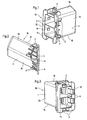
- FIG. 1 to 3 show a first connector part 10 of a two-part electrical connector 12 (see Fig. 10) with a housing 1 which is provided at one end 14 with an opening for receiving the second connector part 8 of the electrical connector 12.
- the housing 1 of this first connector part 10 has on a first side 16 one or more stops 2, on at least one side 16 adjacent to this side 18 one or more end stops 3, wherein on two opposite sides 18 of the housing 1 each at least one such End stop 3 may be provided on one side, here for example again on the first side 16, one or more locking arms 4, a collar 5, which preferably surrounds the open end 14 of the housing 1, and on one of the first side 16 opposite second side 20 one or more further stops. 6
- the latching arms 4 extend from an axially inner region into the region of the open end 14 of the housing 1 or into the region of the collar 5 (cf., in particular, FIG.
- the stops 2 have a greater radial extent than the collar 5. In this case, these stops 2 are axially spaced from the collar 5.
- the other stops 6 have a smaller radial extent than the collar 5. These further stops 6 are again spaced axially from the collar 5.
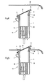
- the housing 1 of the first connector part 10 in an opening 22, for example, made of metal wall or panel 7 can be mounted in the manner shown. It is in particular in the opening 22 of the wall 7 latched and thereby fixed in a defined end position with respect to the wall 7. As can be seen with reference to FIGS. 4 to 9, the latching takes place in the present case in the region of the open end 14 of the housing first
- the housing 1 is moved in the axial direction A (cf., for example, FIG. 4) and at a small angle to the axial direction A (cf., for example, FIG. 5) until the entire collar 5 and the further stops 6 pass through the opening 22 (FIG. see Figures 4 and 6).
- the stops 2 provided on the first side 16 of the housing 1 engage the wall 7 (see Fig. 6) in order to prevent further passage of the housing 1 through the opening 22.
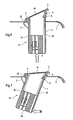
- the housing 1 is then pressed in the direction of the end 24 facing away from the open end 14 in a direction substantially perpendicular to the axial direction A, to cause a pivoting movement of the housing 1 by a certain angle with respect to the axial direction A (see FIG. 7). In this case, the housing 1 is pivoted so far until the collar 5 with the wall 7 is engaged (see FIG .. 8).
- the latching arms 4 come into engagement with the edge of the opening 22, wherein they are pushed back against their spring force. Thus, a kind of biasing force is generated in order to displace the housing 1 in a direction substantially perpendicular to the axial direction A (see FIG. 8). Finally, the housing 1 engages in the opening 22 of the wall 7, wherein a wall portion between the provided on the second side 20 of the housing 1 stops 6 and the collar 5 is included (see Fig. 9).
- the further stops 6 are each provided with a run-on slope 26, via which the first connector part 10 is supported on the opening edge during pivoting.
- the housing 1 is thus fixed and secured in the opening 22 of the wall 7, before the second connector part 8 (cf., Fig. 10) of the electrical connector 12 is mated with the first connector part 10.
- the assembly of the first connector part 10 in the wall 7 is facilitated.
- the mating of the two connector parts 10, 8 is simplified, in particular, the problems previously encountered in connection with the small available space are eliminated.
- the housing 1 is also provided with internal locking means 9, which cooperate with counter-locking means of the other connector part 8.
- the inner locking means 9 are formed by inner locking projections.
- the second connector part 8 engages with the latching arms 4 to prevent movement of these latching arms 4 and thus removal of the housing 1 from the wall 7. If the housing 1 is not correctly positioned in the opening 22 of the wall 7, then the locking arms 4 are biased inwardly, whereby insertion of the second connector part 8 and a correspondingly correct mating of the two connector parts 10, 8 is prevented.
- the connector part 10 occupying its end position can be inclined with respect to the normal of the wall 7 having the opening 22.
- the inclination angle may be, for example, in a range of about 25 °.
- the collar 5 lies in a plane whose normal to the axial or longitudinal direction of the connector part 10 is inclined.
- the angle of inclination can be correspondingly, for example, in a range of about 25 °.
- the invention can be used for example in motor vehicles. Basically, however, an application in other areas is conceivable. For example, an application is generally possible where it comes to mounting a connector part of an electrical connector in an opening of a wall.
Landscapes
- Details Of Connecting Devices For Male And Female Coupling (AREA)
- Connector Housings Or Holding Contact Members (AREA)
Claims (25)
- Pièce de connecteur (10) d'un connecteur (12) électrique en deux parties, réalisée de manière à pouvoir être encliquetée dans une ouverture (22) d'une paroi (7) et susceptible d'être fixée en une position finale définie par rapport à la paroi (7), son boîtier (1) étant muni, sur un premier côté (16), d'au moins une butée (2) qui, lors du passage de la pièce de connecteur (10) à travers l'ouverture de paroi (22), vient en prise avec la paroi (7) et limite de ce fait le déplacement de traversée de la pièce de connecteur (10) par rapport à la paroi (7),
caractérisée en ce qu'
au moins un bras d'encliquetage (4) est prévu sur le premier côté (16) du boîtier (1), en ce que le boîtier (1) est muni, sur un deuxième côté (20) opposé au premier côté, d'au moins une autre butée (6) disposée à distance axiale d'une collerette (5) du boîtier, lorsque la pièce de connecteur (10) est encliquetée à la paroi (7) et a pris sa position finale, un tronçon de paroi, délimitant l'ouverture (22), étant inclus dans la zone entre la collerette (5) et l'autre butée (6), et en ce que, après avoir effectué l'enfichage de la pièce de connecteur (10) à travers l'ouverture de paroi (22), la pièce de connecteur (10) est susceptible d'être encliquetée à la paroi (7), par un pivotement subséquent suivi d'une translation, effectuée parallèlement à la paroi, le bras d'encliquetage (4) étant refoulé, pendant le pivotement, à l'encontre de sa force élastique et la pièce de connecteur (10) étant déplaçable, en étant soutenue par la force élastique du bras d'encliquetage (4) parallèlement à la paroi (7), pour introduire le tronçon de paroi concerné dans la zone se trouvant entre la collerette (5) et l'autre butée (6). - Pièce de connecteur selon la revendication 1, caractérisée en ce qu'elle est encliquetable dans la zone d'une (14) de ses deux extrémités, dans l'ouverture de paroi (22).
- Pièce de connecteur selon la revendication 2, caractérisée en ce que l'extrémité (14) concernée est ouverte, afin de recevoir l'autre pièce de connecteur (8).
- Pièce de connecteur selon l'une des revendications précédentes, caractérisée en ce qu'au moins un côté (18) limitrophe au premier côté (16) du boîtier (1) est muni d'au moins une butée finale (3) qui vient en appui sur la paroi (7) lorsque la pièce de connecteur a pris sa position finale
- Pièce de connecteur selon la revendication 4, caractérisée en ce que chaque fois au moins une butée finale (3) est prévue sur deux côtés (18) opposés l'un à l'autre du boîtier (1).
- Pièce de connecteur selon l'une des revendications précédentes, caractérisée en ce qu'au moins un côté (16) du boîtier (1) est muni d'au moins un bras d'encliquetage (4).
- Pièce de connecteur selon l'une des revendications précédentes, caractérisée en ce que, lorsque la pièce de connecteur (10) prend sa position finale, la collerette (5) vient en appui sur la paroi (7) sur la face, opposée par rapport à la butée (2) ou à la butée finale (3).
- Pièce de connecteur selon la revendication 7, caractérisée en ce que la collerette (5) est prévue sur l'extrémité (14) concernée de la pièce de connecteur (10).
- Pièce de connecteur selon la revendication 7 ou 8, caractérisée en ce que la collerette (5) entoure l'extrémité (14) ouverte du boîtier (1).
- Pièce de connecteur selon l'une des revendications précédentes, caractérisée en ce que le bras d'encliquetage (4), en partant d'une zone située axialement intérieurement, s'étend jusque dans la zone d'une extrémité (14) ouverte du boîtier (1), ou dans la zone de la collerette (5).
- Pièce de connecteur selon l'une des revendications précédentes, caractérisée en ce que la butée (2) présente une étendue radiale plus grande que ne le fait la collerette (5).
- Pièce de connecteur selon l'une des revendications précédentes, caractérisée en ce que la butée (2) est espacée axialement de la collerette (5).
- Pièce de connecteur selon l'une des revendications précédentes, caractérisée en ce que l'autre butée (6) présente une étendue radiale plus petite que ne le fait la collerette (5).
- Pièce de connecteur selon l'une des revendications précédentes, caractérisée en ce que la pièce de connecteur (10) prenant sa position finale est inclinée par rapport à la normale de la paroi (7) présentant l'ouverture (22).
- Pièce de connecteur selon la revendication 14, caractérisée en ce que l'angle d'inclinaison est de l'ordre d'environ 25°.
- Pièce de connecteur selon la revendication 14 ou 15, caractérisée en ce que la collerette (5) est située dans un plan dont la normale est inclinée par rapport à la direction axiale ou longitudinale de la pièce de connecteur (10).
- Pièce de connecteur selon la revendication 16, caractérisée en ce que l'angle d'inclinaison est de l'ordre d'environ 25°.
- Pièce de connecteur selon l'une des revendications précédentes, caractérisée en ce que l'autre butée (6) est munie d'une pente de franchissement (26), par l'intermédiaire de laquelle la pièce de connecteur (10) prend appui sur le bord d'ouverture pendant le pivotement.
- Pièce de connecteur selon l'une des revendications précédentes, caractérisée en ce qu'elle est munie de moyens d'encliquetage (9) intérieurs, coopérant avec des moyens d'encliquetage conjugués, appartenant à l'autre pièce de connecteur (8).
- Connecteur électrique (12) ayant deux pièces de connecteur (10, 8) susceptibles d'être assemblées par emboîtement, pouvant être encliquetées ensemble, une première pièce de connecteur (10) étant réalisée selon l'une des revendications précédentes.
- Connecteur électrique selon la revendication 20, caractérisé en ce que les deux pièces de connecteur (10, 8) ne sont susceptibles d'être assemblées complètement par emboîtement et d'être encliquetées ensemble que si la première pièce de connecteur (10) est encliquetée dans l'ouverture (22) de la paroi (7) et est ainsi fixée à sa position finale.
- Connecteur électrique selon la revendication 21, caractérisé en ce que, lorsque la première pièce de connecteur (10) n'est pas encliquetée à la paroi (7), un assemblage complet par emboîtement et un encliquetage des deux pièces de connecteur (10, 8) sont empêchés, par le bras d'encliquetage (4) refoulé vers l'intérieur.
- Connecteur électrique selon l'une des revendications 20 à 22, caractérisé en ce que, lorsque les pièces de connecteur (10, 8) sont complètement assemblées par emboîtement et encliquetées ensemble, le bras d'encliquetage (4) est assuré à sa position d'encliquetage par la deuxième pièce de connecteur (8).
- Connecteur électrique selon l'une des revendications 20 à 22, caractérisé en ce qu'une pince ayant un passe-fils associé est prévue pour l'étanchéité vers l'extérieur de la liaison sur la paroi (7).
- Connecteur électrique selon la revendication 24, caractérisé en ce que la pince à passe-fils associé n'est montable que si les deux pièces de connecteur (10, 8) sont complètement assemblées par emboîtement et encliquetées ensemble.
Applications Claiming Priority (2)
| Application Number | Priority Date | Filing Date | Title |
|---|---|---|---|
| GBGB0406706.2A GB0406706D0 (en) | 2004-03-25 | 2004-03-25 | Electrical connector |
| GB0406706 | 2004-03-25 |
Publications (2)
| Publication Number | Publication Date |
|---|---|
| EP1580850A1 EP1580850A1 (fr) | 2005-09-28 |
| EP1580850B1 true EP1580850B1 (fr) | 2007-01-24 |
Family
ID=32188663
Family Applications (1)
| Application Number | Title | Priority Date | Filing Date |
|---|---|---|---|
| EP04019101A Active EP1580850B1 (fr) | 2004-03-25 | 2004-08-11 | Connecteur électrique |
Country Status (4)
| Country | Link |
|---|---|
| EP (1) | EP1580850B1 (fr) |
| AT (1) | ATE352894T1 (fr) |
| DE (1) | DE502004002767D1 (fr) |
| GB (1) | GB0406706D0 (fr) |
Families Citing this family (4)
| Publication number | Priority date | Publication date | Assignee | Title |
|---|---|---|---|---|
| ES2345235B1 (es) | 2008-07-21 | 2011-08-17 | Bsh Electrodomesticos España, S.A | Carcasa termoaislante con paso de conducto. |
| DE102014113481A1 (de) * | 2014-09-18 | 2016-03-24 | Harting Electric Gmbh & Co. Kg | Steckverbindergehäuse mit einer Dichtung |
| DE102017122649A1 (de) * | 2017-09-28 | 2019-03-28 | Unger Kabel-Konfektionstechnik GmbH | Gerätestecker mit Sperrsystem für die Gerätedose bei Fehlmontage, Geräteanschlusssystem und Elektrogerät |
| DE102020105580B4 (de) * | 2020-03-03 | 2022-03-24 | Phoenix Contact Gmbh & Co. Kg | Befestigungsklemme zur Fixierung mindestens einer Reihenklemme in einer Wandöffnung |
Family Cites Families (6)
| Publication number | Priority date | Publication date | Assignee | Title |
|---|---|---|---|---|
| US5178554A (en) * | 1990-10-26 | 1993-01-12 | The Siemon Company | Modular jack patching device |
| JP3075445B2 (ja) * | 1992-11-04 | 2000-08-14 | 矢崎総業株式会社 | パネルに対するコネクタの取付方法及び取付構造 |
| JP2973866B2 (ja) * | 1995-04-24 | 1999-11-08 | 住友電装株式会社 | 待ち受けコネクタ |
| TW433604U (en) * | 1999-11-02 | 2001-05-01 | Hon Hai Prec Ind Co Ltd | Connector having a locking device |
| US6582132B1 (en) * | 2000-05-09 | 2003-06-24 | Molex Incorporated | Connector panel mount system |
| US6623170B2 (en) * | 2001-06-20 | 2003-09-23 | Fci Americas Technology, Inc. | Angular mounted optical connector adaptor frame |
-
2004
- 2004-03-25 GB GBGB0406706.2A patent/GB0406706D0/en not_active Ceased
- 2004-08-11 DE DE502004002767T patent/DE502004002767D1/de not_active Expired - Fee Related
- 2004-08-11 EP EP04019101A patent/EP1580850B1/fr active Active
- 2004-08-11 AT AT04019101T patent/ATE352894T1/de not_active IP Right Cessation
Also Published As
| Publication number | Publication date |
|---|---|
| DE502004002767D1 (de) | 2007-03-15 |
| EP1580850A1 (fr) | 2005-09-28 |
| GB0406706D0 (en) | 2004-04-28 |
| ATE352894T1 (de) | 2007-02-15 |
Similar Documents
| Publication | Publication Date | Title |
|---|---|---|
| DE102017208108B4 (de) | Weibliche und männliche Steckverbinder | |
| DE102007052606B3 (de) | Elektrischer Steckverbinder, insbesondere elektrischer Stift- oder Buchsenverbinder | |
| DE10016943C2 (de) | Abschirmverbindungselement | |
| EP1760837B1 (fr) | Connecteur électrique à force d' insertion nulle | |
| DE19500959C2 (de) | Elektrischer Steckverbinder | |
| DE102009006441B4 (de) | Leichtkraftsteckverbinder | |
| EP1851819B1 (fr) | Antenne et element destine a fixer l'antenne sur un vehicule et a connecter l'antenne a un ou plusieurs cables d'un faisceau de cables dispose dans le vehicule | |
| DE19625601B4 (de) | Steckerverbinderanordnung mit Mechanismus zur Bestätigung des Sitzes der Steckverbindergehäuse und Verfahren zur Befestigung der Steckverbindergehäuse | |
| EP2415122B1 (fr) | Connecteur à fiches destiné à être connecté à un câble coaxial | |
| WO2008061572A2 (fr) | Connecteur enfichable blindé et son procédé de réalisation | |
| EP3266076B1 (fr) | Procédé de montage d'un connecteur coudé à fiche et unité de montage pour produire un connecteur coudé à fiche | |
| DE102010039314A1 (de) | Elektrischer Steckverbinder | |
| DE112018001914B4 (de) | Innenleiteranschluss und abgeschirmter Verbinder | |
| EP1744408B1 (fr) | Connexion enfichable électrique | |
| DE19848411A1 (de) | Abgeschirmter Stecker | |
| DE10393763T5 (de) | Schaltungsplattenverbinder mit einstückiger dielektrischer Abdeckung | |
| DE10131936A1 (de) | Verbinder-Haltemechanismus | |
| DE10346925A1 (de) | Verbinder | |
| EP2337154A1 (fr) | Dispositif de connexion | |
| DE102016124496B3 (de) | Universaladapter für einen Steckverbinderkopf sowie Steckverbinderteil mit einem derartigen Steckverbinderkopf | |
| EP1580850B1 (fr) | Connecteur électrique | |
| DE102004041809B4 (de) | Winkelkuppler | |
| DE102018126448A1 (de) | Elektrischer Steckverbinder und elektrische Steckverbindung | |
| DE102009014634A1 (de) | LIF-Stecker | |
| EP2018693B1 (fr) | Profile electrique pour traversees de cables |
Legal Events
| Date | Code | Title | Description |
|---|---|---|---|
| PUAI | Public reference made under article 153(3) epc to a published international application that has entered the european phase |
Free format text: ORIGINAL CODE: 0009012 |
|
| AK | Designated contracting states |
Kind code of ref document: A1 Designated state(s): AT BE BG CH CY CZ DE DK EE ES FI FR GB GR HU IE IT LI LU MC NL PL PT RO SE SI SK TR |
|
| AX | Request for extension of the european patent |
Extension state: AL HR LT LV MK |
|
| 17P | Request for examination filed |
Effective date: 20051021 |
|
| AKX | Designation fees paid |
Designated state(s): AT BE BG CH CY CZ DE DK EE ES FI FR GB GR HU IE IT LI LU MC NL PL PT RO SE SI SK TR |
|
| GRAP | Despatch of communication of intention to grant a patent |
Free format text: ORIGINAL CODE: EPIDOSNIGR1 |
|
| GRAS | Grant fee paid |
Free format text: ORIGINAL CODE: EPIDOSNIGR3 |
|
| GRAA | (expected) grant |
Free format text: ORIGINAL CODE: 0009210 |
|
| AK | Designated contracting states |
Kind code of ref document: B1 Designated state(s): AT BE BG CH CY CZ DE DK EE ES FI FR GB GR HU IE IT LI LU MC NL PL PT RO SE SI SK TR |
|
| PG25 | Lapsed in a contracting state [announced via postgrant information from national office to epo] |
Ref country code: DK Free format text: LAPSE BECAUSE OF FAILURE TO SUBMIT A TRANSLATION OF THE DESCRIPTION OR TO PAY THE FEE WITHIN THE PRESCRIBED TIME-LIMIT Effective date: 20070124 Ref country code: IE Free format text: LAPSE BECAUSE OF FAILURE TO SUBMIT A TRANSLATION OF THE DESCRIPTION OR TO PAY THE FEE WITHIN THE PRESCRIBED TIME-LIMIT Effective date: 20070124 Ref country code: FI Free format text: LAPSE BECAUSE OF FAILURE TO SUBMIT A TRANSLATION OF THE DESCRIPTION OR TO PAY THE FEE WITHIN THE PRESCRIBED TIME-LIMIT Effective date: 20070124 Ref country code: PL Free format text: LAPSE BECAUSE OF FAILURE TO SUBMIT A TRANSLATION OF THE DESCRIPTION OR TO PAY THE FEE WITHIN THE PRESCRIBED TIME-LIMIT Effective date: 20070124 Ref country code: NL Free format text: LAPSE BECAUSE OF FAILURE TO SUBMIT A TRANSLATION OF THE DESCRIPTION OR TO PAY THE FEE WITHIN THE PRESCRIBED TIME-LIMIT Effective date: 20070124 Ref country code: SI Free format text: LAPSE BECAUSE OF FAILURE TO SUBMIT A TRANSLATION OF THE DESCRIPTION OR TO PAY THE FEE WITHIN THE PRESCRIBED TIME-LIMIT Effective date: 20070124 |
|
| REG | Reference to a national code |
Ref country code: GB Ref legal event code: FG4D Free format text: NOT ENGLISH |
|
| REG | Reference to a national code |
Ref country code: CH Ref legal event code: EP |
|
| REG | Reference to a national code |
Ref country code: IE Ref legal event code: FG4D Free format text: LANGUAGE OF EP DOCUMENT: GERMAN |
|
| REF | Corresponds to: |
Ref document number: 502004002767 Country of ref document: DE Date of ref document: 20070315 Kind code of ref document: P |
|
| PG25 | Lapsed in a contracting state [announced via postgrant information from national office to epo] |
Ref country code: SE Free format text: LAPSE BECAUSE OF FAILURE TO SUBMIT A TRANSLATION OF THE DESCRIPTION OR TO PAY THE FEE WITHIN THE PRESCRIBED TIME-LIMIT Effective date: 20070424 |
|
| PG25 | Lapsed in a contracting state [announced via postgrant information from national office to epo] |
Ref country code: BG Free format text: LAPSE BECAUSE OF FAILURE TO SUBMIT A TRANSLATION OF THE DESCRIPTION OR TO PAY THE FEE WITHIN THE PRESCRIBED TIME-LIMIT Effective date: 20070425 |
|
| PG25 | Lapsed in a contracting state [announced via postgrant information from national office to epo] |
Ref country code: ES Free format text: LAPSE BECAUSE OF FAILURE TO SUBMIT A TRANSLATION OF THE DESCRIPTION OR TO PAY THE FEE WITHIN THE PRESCRIBED TIME-LIMIT Effective date: 20070505 |
|
| PG25 | Lapsed in a contracting state [announced via postgrant information from national office to epo] |
Ref country code: PT Free format text: LAPSE BECAUSE OF FAILURE TO SUBMIT A TRANSLATION OF THE DESCRIPTION OR TO PAY THE FEE WITHIN THE PRESCRIBED TIME-LIMIT Effective date: 20070625 |
|
| NLV1 | Nl: lapsed or annulled due to failure to fulfill the requirements of art. 29p and 29m of the patents act | ||
| ET | Fr: translation filed | ||
| GBV | Gb: ep patent (uk) treated as always having been void in accordance with gb section 77(7)/1977 [no translation filed] |
Effective date: 20070124 |
|
| REG | Reference to a national code |
Ref country code: IE Ref legal event code: FD4D |
|
| PG25 | Lapsed in a contracting state [announced via postgrant information from national office to epo] |
Ref country code: SK Free format text: LAPSE BECAUSE OF FAILURE TO SUBMIT A TRANSLATION OF THE DESCRIPTION OR TO PAY THE FEE WITHIN THE PRESCRIBED TIME-LIMIT Effective date: 20070124 Ref country code: GB Free format text: LAPSE BECAUSE OF FAILURE TO SUBMIT A TRANSLATION OF THE DESCRIPTION OR TO PAY THE FEE WITHIN THE PRESCRIBED TIME-LIMIT Effective date: 20070124 |
|
| PLBE | No opposition filed within time limit |
Free format text: ORIGINAL CODE: 0009261 |
|
| STAA | Information on the status of an ep patent application or granted ep patent |
Free format text: STATUS: NO OPPOSITION FILED WITHIN TIME LIMIT |
|
| 26N | No opposition filed |
Effective date: 20071025 |
|
| PG25 | Lapsed in a contracting state [announced via postgrant information from national office to epo] |
Ref country code: RO Free format text: LAPSE BECAUSE OF FAILURE TO SUBMIT A TRANSLATION OF THE DESCRIPTION OR TO PAY THE FEE WITHIN THE PRESCRIBED TIME-LIMIT Effective date: 20070124 Ref country code: CZ Free format text: LAPSE BECAUSE OF FAILURE TO SUBMIT A TRANSLATION OF THE DESCRIPTION OR TO PAY THE FEE WITHIN THE PRESCRIBED TIME-LIMIT Effective date: 20070124 |
|
| BERE | Be: lapsed |
Owner name: DELPHI TECHNOLOGIES, INC. Effective date: 20070831 |
|
| PG25 | Lapsed in a contracting state [announced via postgrant information from national office to epo] |
Ref country code: MC Free format text: LAPSE BECAUSE OF NON-PAYMENT OF DUE FEES Effective date: 20070831 Ref country code: GR Free format text: LAPSE BECAUSE OF FAILURE TO SUBMIT A TRANSLATION OF THE DESCRIPTION OR TO PAY THE FEE WITHIN THE PRESCRIBED TIME-LIMIT Effective date: 20070425 |
|
| REG | Reference to a national code |
Ref country code: FR Ref legal event code: ST Effective date: 20080430 |
|
| PG25 | Lapsed in a contracting state [announced via postgrant information from national office to epo] |
Ref country code: DE Free format text: LAPSE BECAUSE OF NON-PAYMENT OF DUE FEES Effective date: 20080301 |
|
| PG25 | Lapsed in a contracting state [announced via postgrant information from national office to epo] |
Ref country code: BE Free format text: LAPSE BECAUSE OF NON-PAYMENT OF DUE FEES Effective date: 20070831 |
|
| PG25 | Lapsed in a contracting state [announced via postgrant information from national office to epo] |
Ref country code: FR Free format text: LAPSE BECAUSE OF NON-PAYMENT OF DUE FEES Effective date: 20070831 |
|
| PG25 | Lapsed in a contracting state [announced via postgrant information from national office to epo] |
Ref country code: AT Free format text: LAPSE BECAUSE OF NON-PAYMENT OF DUE FEES Effective date: 20070811 |
|
| PG25 | Lapsed in a contracting state [announced via postgrant information from national office to epo] |
Ref country code: EE Free format text: LAPSE BECAUSE OF FAILURE TO SUBMIT A TRANSLATION OF THE DESCRIPTION OR TO PAY THE FEE WITHIN THE PRESCRIBED TIME-LIMIT Effective date: 20070124 |
|
| REG | Reference to a national code |
Ref country code: CH Ref legal event code: PL |
|
| PG25 | Lapsed in a contracting state [announced via postgrant information from national office to epo] |
Ref country code: CH Free format text: LAPSE BECAUSE OF NON-PAYMENT OF DUE FEES Effective date: 20080831 Ref country code: LI Free format text: LAPSE BECAUSE OF NON-PAYMENT OF DUE FEES Effective date: 20080831 |
|
| PG25 | Lapsed in a contracting state [announced via postgrant information from national office to epo] |
Ref country code: CY Free format text: LAPSE BECAUSE OF FAILURE TO SUBMIT A TRANSLATION OF THE DESCRIPTION OR TO PAY THE FEE WITHIN THE PRESCRIBED TIME-LIMIT Effective date: 20070124 |
|
| PG25 | Lapsed in a contracting state [announced via postgrant information from national office to epo] |
Ref country code: LU Free format text: LAPSE BECAUSE OF NON-PAYMENT OF DUE FEES Effective date: 20070811 |
|
| PG25 | Lapsed in a contracting state [announced via postgrant information from national office to epo] |
Ref country code: HU Free format text: LAPSE BECAUSE OF FAILURE TO SUBMIT A TRANSLATION OF THE DESCRIPTION OR TO PAY THE FEE WITHIN THE PRESCRIBED TIME-LIMIT Effective date: 20070725 Ref country code: TR Free format text: LAPSE BECAUSE OF FAILURE TO SUBMIT A TRANSLATION OF THE DESCRIPTION OR TO PAY THE FEE WITHIN THE PRESCRIBED TIME-LIMIT Effective date: 20070124 |
|
| PGFP | Annual fee paid to national office [announced via postgrant information from national office to epo] |
Ref country code: IT Payment date: 20070831 Year of fee payment: 4 |