EP1580850B1 - Electrical connector - Google Patents
Electrical connector Download PDFInfo
- Publication number
- EP1580850B1 EP1580850B1 EP04019101A EP04019101A EP1580850B1 EP 1580850 B1 EP1580850 B1 EP 1580850B1 EP 04019101 A EP04019101 A EP 04019101A EP 04019101 A EP04019101 A EP 04019101A EP 1580850 B1 EP1580850 B1 EP 1580850B1
- Authority
- EP
- European Patent Office
- Prior art keywords
- connector part
- accordance
- wall
- connector
- collar
- Prior art date
- Legal status (The legal status is an assumption and is not a legal conclusion. Google has not performed a legal analysis and makes no representation as to the accuracy of the status listed.)
- Active
Links
Images


Classifications
-
- H—ELECTRICITY
- H01—ELECTRIC ELEMENTS
- H01R—ELECTRICALLY-CONDUCTIVE CONNECTIONS; STRUCTURAL ASSOCIATIONS OF A PLURALITY OF MUTUALLY-INSULATED ELECTRICAL CONNECTING ELEMENTS; COUPLING DEVICES; CURRENT COLLECTORS
- H01R13/00—Details of coupling devices of the kinds covered by groups H01R12/70 or H01R24/00 - H01R33/00
- H01R13/73—Means for mounting coupling parts to apparatus or structures, e.g. to a wall
- H01R13/74—Means for mounting coupling parts in openings of a panel
- H01R13/741—Means for mounting coupling parts in openings of a panel using snap fastening means
Definitions
- the invention relates to a connector part of a two-part electrical connector, which is designed so that connector part of a two-part electrical connector, which is designed so that it can be locked in an opening of a wall and thereby fixed in a defined end position relative to the wall, wherein its housing is provided on a first side with at least one stop which engages in the passage of the connector part through the wall opening with the wall and thereby limits the insertion movement of the connector part relative to the wall. It further relates to an electrical connector with two mating, latchable together connector parts.
- Motor vehicles include a body harness and a door harness.
- the body and door harnesses are electrically coupled together via a two-piece electrical connector where the door is pivotally mounted to a pillar of the body.
- the two connector parts of the connector are electrically connected together and then one of the two connector parts is mounted in an opening of a door pillar.
- this can lead to difficulties in assembly, which are mainly due to the limited space.
- a connector part of the type mentioned is known from EP-A-O 487 893.
- a latching arm is provided on a side of the housing adjacent to the first side.
- a stop is again provided on a first side of the housing, which engages in the insertion of the connector part through the wall opening with the wall.
- a latching arm is provided on a side opposite the first side of the housing.
- Connector parts which can be latched in an opening of a wall and thereby fixed in a defined end position with respect to the wall, for example, from the publications EP-A-0 740 371 and US-A-5,487,680 known.
- the invention has for its object to provide an improved connector part and an improved connector of the type mentioned, in which the aforementioned problems are eliminated.
- At least one locking arm is provided on the first side of the housing, that the housing is provided on one of the first side opposite second side with at least one further stop, which is axially spaced from the collar that when latched to the wall, its end position engaging connector part an opening bounding wall portion in the area between the collar and the further stop is included and that after successful passing through the relevant end of the connector part through the wall opening the connector part by subsequent pivoting and subsequent wall-parallel displacement can be locked with the wall, being pushed back against the spring force during pivoting of the latching arm and the connector part is then supported by the spring force of the latching arm parallel to the wall displaceable to the respective Wandabschni tt in the area between the collar and the further stop.
- the relevant connector part may be, for example, a plug part or a receiving part.
- the invention can be used for example in motor vehicles. In principle, however, other applications are conceivable.
- the connector part is preferably latched in the wall opening in the region of one of its two ends.
- the respective end may be open for receiving the other connector part.
- At least one side of the housing adjacent to the first side is provided with at least one end stop, which rests against the wall at its end position engaging connector part.
- at least one end stop is preferably provided on two opposite sides of the housing.
- At least one side of the housing may in particular be provided with at least one latching arm.
- the housing is provided with a collar which rests against the wall at its end position engaging connector part on the side remote from the stop or end stop.
- the collar can be provided in particular at the respective end of the connector part.
- the collar encloses the open end of the housing.
- the latching arm advantageously extends from an axially inner region to the region of the open end of the housing or into the region of the collar.
- the stopper preferably has a larger radial extent than the collar.
- the stop is axially spaced from the collar.
- the further stop preferably has a smaller radial extent than the collar.
- the connector part occupying its end position is inclined relative to the normal of the wall having the opening.
- the inclination angle may be, for example, in a range of about 25 °.
- the collar lies in a plane whose normal to the axial or longitudinal direction of the connector part is inclined.
- the inclination angle corresponding to, for example, again in a range of about 25 °.
- the further stop can be provided in particular with a ramp, over which the connector part is supported during the pivoting at the opening edge.
- the connector part is expediently provided with internal locking means which cooperate with counter-locking means of the other connector part.
- the relevant connector part may be, for example, a plug part or else a receiving part.
- the electrical connector according to the invention comprises two plug-together, latchable together connector parts, of which at least one is formed by an inventive connector part.
- the two connector parts of the connector are only completely plugged together and locked together, when the first connector part is locked in the opening of the wall and thus fixed in its end position.
- a complete mating and locking of the two connector parts can be prevented in particular by the latching inwardly latched in not latched to the wall first connector part.
- a clamp with associated spout can be provided.
- this clip with associated spout is only mountable when the two connector parts are completely plugged together and locked together.
- the electrical connector according to the invention thus comprises a first connector part according to the invention, which may, for example, be a plug part, and a second connector part, that is, for example, a receiving part.
- the connector part designed according to the invention can also be a receiving part.
- a clip can be used to close the connection and cover with a spout.
- the plug part connected to the body harness is installed first.
- This can initially be done in a conventional manner, that the plug part is moved from the vehicle interior side directly into the column and through the outer opening for the connector to a position in which the connector part is stopped by stops on the housing of the connector part.
- the plug part In this locked position, the plug part can be slightly pushed sideways until it locks in the end position in which it is fixed with respect to the wall.
- the plug part is arranged inside the column, e.g. at an angle of about 25 ° to the normal to the wall, taking up little space. This brings in comparison with the usual connectors advantages.
- the entire connection between the plug part and the receiving part is spent in the interior of the column, so that no space between the door and the column is required. This results in an improved connection, since the receiving part is easy to install at an angle, even if there is little space between the column and the door.
- the assembled connector part is fixed in its final position and requires no further handling during the assembly process.
- the next step is before or after coupling the door to the chassis of the vehicle.
- the fitter grips the cable harness coming from the door with the receiving part and the grommet arranged at the cable end and guides the receiving part into the plug part fixed within the column.
- the receiving part can only be inserted when the plug part assumes its correct fixed position within the column. moreover blocks the locked receiving part of the connector assembly in the column so that it can not be removed. This happens for example by two locking arms on the plug part.
- the assembly of the clip which is mounted with a grommet, to cover the connection to the column and seal it to the outside.
- the determination of the clip and the spout requires a complete completion of the previous assembly operation with respect to the locked receiving part.
- a finger may be provided on the clip, which comes into contact with the receiving part.
- the receiving part and the spout can also be mounted with one hand after the plug part occupies a fixed position from the beginning of the door mounting operation.
- the plug part mounted in the door and the receiving part can be attached to the end of the body harness.
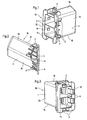
- FIG. 1 to 3 show a first connector part 10 of a two-part electrical connector 12 (see Fig. 10) with a housing 1 which is provided at one end 14 with an opening for receiving the second connector part 8 of the electrical connector 12.
- the housing 1 of this first connector part 10 has on a first side 16 one or more stops 2, on at least one side 16 adjacent to this side 18 one or more end stops 3, wherein on two opposite sides 18 of the housing 1 each at least one such End stop 3 may be provided on one side, here for example again on the first side 16, one or more locking arms 4, a collar 5, which preferably surrounds the open end 14 of the housing 1, and on one of the first side 16 opposite second side 20 one or more further stops. 6
- the latching arms 4 extend from an axially inner region into the region of the open end 14 of the housing 1 or into the region of the collar 5 (cf., in particular, FIG.
- the stops 2 have a greater radial extent than the collar 5. In this case, these stops 2 are axially spaced from the collar 5.
- the other stops 6 have a smaller radial extent than the collar 5. These further stops 6 are again spaced axially from the collar 5.
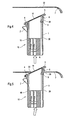
- the housing 1 of the first connector part 10 in an opening 22, for example, made of metal wall or panel 7 can be mounted in the manner shown. It is in particular in the opening 22 of the wall 7 latched and thereby fixed in a defined end position with respect to the wall 7. As can be seen with reference to FIGS. 4 to 9, the latching takes place in the present case in the region of the open end 14 of the housing first
- the housing 1 is moved in the axial direction A (cf., for example, FIG. 4) and at a small angle to the axial direction A (cf., for example, FIG. 5) until the entire collar 5 and the further stops 6 pass through the opening 22 (FIG. see Figures 4 and 6).
- the stops 2 provided on the first side 16 of the housing 1 engage the wall 7 (see Fig. 6) in order to prevent further passage of the housing 1 through the opening 22.
- the housing 1 is then pressed in the direction of the end 24 facing away from the open end 14 in a direction substantially perpendicular to the axial direction A, to cause a pivoting movement of the housing 1 by a certain angle with respect to the axial direction A (see FIG. 7). In this case, the housing 1 is pivoted so far until the collar 5 with the wall 7 is engaged (see FIG .. 8).
- the latching arms 4 come into engagement with the edge of the opening 22, wherein they are pushed back against their spring force. Thus, a kind of biasing force is generated in order to displace the housing 1 in a direction substantially perpendicular to the axial direction A (see FIG. 8). Finally, the housing 1 engages in the opening 22 of the wall 7, wherein a wall portion between the provided on the second side 20 of the housing 1 stops 6 and the collar 5 is included (see Fig. 9).
- the further stops 6 are each provided with a run-on slope 26, via which the first connector part 10 is supported on the opening edge during pivoting.
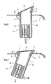
- the housing 1 is thus fixed and secured in the opening 22 of the wall 7, before the second connector part 8 (cf., Fig. 10) of the electrical connector 12 is mated with the first connector part 10.
- the assembly of the first connector part 10 in the wall 7 is facilitated.
- the mating of the two connector parts 10, 8 is simplified, in particular, the problems previously encountered in connection with the small available space are eliminated.
- the housing 1 is also provided with internal locking means 9, which cooperate with counter-locking means of the other connector part 8.
- the inner locking means 9 are formed by inner locking projections.
- the second connector part 8 engages with the latching arms 4 to prevent movement of these latching arms 4 and thus removal of the housing 1 from the wall 7. If the housing 1 is not correctly positioned in the opening 22 of the wall 7, then the locking arms 4 are biased inwardly, whereby insertion of the second connector part 8 and a correspondingly correct mating of the two connector parts 10, 8 is prevented.
- the connector part 10 occupying its end position can be inclined with respect to the normal of the wall 7 having the opening 22.
- the inclination angle may be, for example, in a range of about 25 °.
- the collar 5 lies in a plane whose normal to the axial or longitudinal direction of the connector part 10 is inclined.
- the angle of inclination can be correspondingly, for example, in a range of about 25 °.
- the invention can be used for example in motor vehicles. Basically, however, an application in other areas is conceivable. For example, an application is generally possible where it comes to mounting a connector part of an electrical connector in an opening of a wall.
Abstract
Description
Die Erfindung betrifft ein Verbinderteil eines zweiteiligen elektrischen Steckverbinders, das so ausgeführt ist, dass Verbinderteil eines zweiteiligen elektrischen Steckverbinders, das so ausgeführt ist, dass es in einer Öffnung einer Wand verrastbar und dabei in einer definierten Endstellung bezüglich der Wand fixierbar ist, wobei sein Gehäuse auf einer ersten Seite mit wenigstens einem Anschlag versehen ist, der beim Hindurchstecken des Verbinderteils durch die Wandöffnung mit der Wand in Eingriff kommt und dadurch die Durchsteckbewegung des Verbinderteils relativ zur Wand begrenzt. Sie betrifft ferner einen elektrischen Steckverbinder mit zwei zusammensteckbaren, miteinander verrastbaren Verbinderteilen.The invention relates to a connector part of a two-part electrical connector, which is designed so that connector part of a two-part electrical connector, which is designed so that it can be locked in an opening of a wall and thereby fixed in a defined end position relative to the wall, wherein its housing is provided on a first side with at least one stop which engages in the passage of the connector part through the wall opening with the wall and thereby limits the insertion movement of the connector part relative to the wall. It further relates to an electrical connector with two mating, latchable together connector parts.
Kraftfahrzeuge umfassen einen Karosserie-Kabelstrang und einen Tür-Kabelstrang. Die Karosserie- und Tür-Kabelstränge werden über einen zweiteiligen elektrischen Steckverbinder dort elektrisch miteinander gekoppelt, wo die Tür schwenkbar an einer Säule der Karosserie angebracht wird. Bei der üblichen Montage werden die beiden Verbinderteile des Steckverbinders elektrisch miteinander verbunden und anschließend wird eines der beiden Verbinderteile in einer Öffnung einer Türsäule montiert. Eine solche Vorgehensweise bringt nun aber eine Reihe von Nachteilen mit sich. So kann es insbesondere zu Schwierigkeiten bei der Montage kommen, die hauptsächlich auf den begrenzten Raum zurückzuführen sind. Zudem besteht die Gefahr einer falschen Paarung oder einer falschen Montage.Motor vehicles include a body harness and a door harness. The body and door harnesses are electrically coupled together via a two-piece electrical connector where the door is pivotally mounted to a pillar of the body. In the usual assembly, the two connector parts of the connector are electrically connected together and then one of the two connector parts is mounted in an opening of a door pillar. However, such a procedure brings with it a number of disadvantages. In particular, this can lead to difficulties in assembly, which are mainly due to the limited space. In addition, there is a risk of miscommunication or incorrect installation.
Ein Verbinderteil der eingangs genannten Art ist aus der EP-A-O 487 893 bekannt. Bei diesem bekannten Verbinderteil ist ein Rastarm auf einer an die erste Seite angrenzenden Seite des Gehäuses vorgesehen.A connector part of the type mentioned is known from EP-A-O 487 893. In this known connector part, a latching arm is provided on a side of the housing adjacent to the first side.
Auch bei einem aus der US-B-6 210 217 bekannten Verbinderteil ist auf einer ersten Seite des Gehäuses wieder ein Anschlag vorgesehen, der beim Hindurchstecken des Verbinderteils durch die Wandöffnung mit der Wand in Eingriff kommt. Ein Rastarm ist auf einer der ersten Seite gegenüberliegenden Seite des Gehäuses vorgesehen.Also, in a connector part known from US-B-6 210 217 a stop is again provided on a first side of the housing, which engages in the insertion of the connector part through the wall opening with the wall. A latching arm is provided on a side opposite the first side of the housing.
Verbinderteile, die in einer Öffnung einer Wand verrastbar und dabei in einer definierten Endstellung bezüglich der Wand fixierbar sind, sind beispielsweise auch aus den Druckschriften EP-A-0 740 371 und US-A-5 487 680 bekannt.Connector parts which can be latched in an opening of a wall and thereby fixed in a defined end position with respect to the wall, for example, from the publications EP-A-0 740 371 and US-A-5,487,680 known.
Der Erfindung liegt die Aufgabe zugrunde, ein verbessertes Verbinderteil sowie einen verbesserten Steckverbinder der eingangs genannten Art zu schaffen, bei denen die zuvor genannten Probleme beseitigt sind.The invention has for its object to provide an improved connector part and an improved connector of the type mentioned, in which the aforementioned problems are eliminated.
Diese Aufgabe wird bezüglich des Verbinderteils dadurch gelöst, dass wenigstens ein Rastarm auf der ersten Seite des Gehäuses vorgesehen ist, dass das Gehäuse auf einer der ersten Seite gegenüber liegenden zweiten Seite mit wenigstens einem weiteren Anschlag versehen ist, der axial vom Kragen beabstandet ist, dass bei mit der Wand verrastetem, seine Endstellung einnehmendem Verbinderteil ein die Öffnung begrenzender Wandabschnitt in dem Bereich zwischen dem Kragen und dem weiteren Anschlag eingeschlossen ist und dass nach erfolgtem Hindurchstecken des betreffenden Endes des Verbinderteils durch die Wandöffnung das Verbinderteil durch anschließendes Verschwenken und darauf folgendes wandparalleles Verschieben mit der Wand verrastbar ist, wobei während des Verschwenkens der Rastarm entgegen dessen Federkraft zurückgedrängt wird und das Verbinderteil anschließend unterstützt durch die Federkraft des Rastarmes parallel zur Wand verschiebbar ist, um den betreffenden Wandabschnitt in dem Bereich zwischen dem Kragen und dem weiteren Anschlag einzuschließen.This object is achieved with respect to the connector part in that at least one locking arm is provided on the first side of the housing, that the housing is provided on one of the first side opposite second side with at least one further stop, which is axially spaced from the collar that when latched to the wall, its end position engaging connector part an opening bounding wall portion in the area between the collar and the further stop is included and that after successful passing through the relevant end of the connector part through the wall opening the connector part by subsequent pivoting and subsequent wall-parallel displacement can be locked with the wall, being pushed back against the spring force during pivoting of the latching arm and the connector part is then supported by the spring force of the latching arm parallel to the wall displaceable to the respective Wandabschni tt in the area between the collar and the further stop.
Bei dem betreffenden Verbinderteil kann es sich beispielsweise um ein Steckerteil oder auch um ein Aufnahmeteil handeln. Die Erfindung ist beispielsweise in Kraftfahrzeugen einsetzbar. Grundsätzlich sind jedoch auch andere Einsatzbereiche denkbar.In the relevant connector part may be, for example, a plug part or a receiving part. The invention can be used for example in motor vehicles. In principle, however, other applications are conceivable.
Das Verbinderteil ist bevorzugt im Bereich eines seiner beiden Enden in der Wandöffnung verrastbar. Das betreffende Ende kann zur Aufnahme des anderen Verbinderteils offen sein.The connector part is preferably latched in the wall opening in the region of one of its two ends. The respective end may be open for receiving the other connector part.
Bevorzugt ist wenigstens eine an die erste Seite angrenzende Seite des Gehäuses mit wenigstens einem Endanschlag versehen, der bei seine Endstellung einnehmenden Verbinderteil an der Wand anliegt. Dabei ist bevorzugt auf zwei einander gegenüberliegenden Seiten des Gehäuses jeweils wenigstens ein Endanschlag vorgesehen.Preferably, at least one side of the housing adjacent to the first side is provided with at least one end stop, which rests against the wall at its end position engaging connector part. In this case, at least one end stop is preferably provided on two opposite sides of the housing.
Wenigstens eine Seite des Gehäuses kann insbesondere mit wenigstens einem Rastarm versehen sein.At least one side of the housing may in particular be provided with at least one latching arm.
Bei einer bevorzugten praktischen Ausführungsform des erfindungsgemäßen Verbinderteils ist das Gehäuse mit einem Kragen versehen, der bei seine Endstellung einnehmendem Verbinderteil auf der vom Anschlag bzw. Endanschlag abgewandten Seite an der Wand anliegt. Dabei kann der Kragen insbesondere am betreffenden Ende des Verbinderteils vorgesehen sein. Bevorzugt umschließt der Kragen das offene Ende des Gehäuses.In a preferred practical embodiment of the connector part according to the invention, the housing is provided with a collar which rests against the wall at its end position engaging connector part on the side remote from the stop or end stop. In this case, the collar can be provided in particular at the respective end of the connector part. Preferably, the collar encloses the open end of the housing.
Der Rastarm erstreckt sich vorteilhafterweise ausgehend von einem axial innen liegenden Bereich bis in den Bereich des offenen Endes des Gehäuses bzw. bis in den Bereich des Kragens.The latching arm advantageously extends from an axially inner region to the region of the open end of the housing or into the region of the collar.
Der Anschlag besitzt bevorzugt eine größere radiale Erstreckung als der Kragen.The stopper preferably has a larger radial extent than the collar.
Zweckmäßigerweise ist der Anschlag axial vom Kragen beabstandet.Conveniently, the stop is axially spaced from the collar.
Der weitere Anschlag besitzt vorzugsweise eine geringere radiale Erstreckung als der Kragen.The further stop preferably has a smaller radial extent than the collar.
Bei einer bevorzugten praktischen Ausführungsform des erfindungsgemäßen Verbinderteils ist das seine Endstellung einnehmende Verbinderteil bezüglich der Normalen der die Öffnung aufweisenden Wand geneigt. Dabei kann der Neigungswinkel beispielsweise in einem Bereich von etwa 25° liegen.In a preferred practical embodiment of the connector part according to the invention, the connector part occupying its end position is inclined relative to the normal of the wall having the opening. In this case, the inclination angle may be, for example, in a range of about 25 °.
Bevorzugt liegt der Kragen in einer Ebene, deren Normale zur Axial- oder Längsrichtung des Verbinderteils geneigt ist. Dabei kann der Neigungswinkel entsprechend beispielsweise wieder in einem Bereich von etwa 25° liegen.Preferably, the collar lies in a plane whose normal to the axial or longitudinal direction of the connector part is inclined. In this case, the inclination angle corresponding to, for example, again in a range of about 25 °.
Der weitere Anschlag kann insbesondere mit einer Auflaufschräge versehen sein, über die sich das Verbinderteil während des Verschwenkens am Öffnungsrand abstützt.The further stop can be provided in particular with a ramp, over which the connector part is supported during the pivoting at the opening edge.
Das Verbinderteil ist zweckmäßigerweise mit inneren Rastmitteln versehen, die mit Gegenrastmitteln des anderen Verbinderteils zusammenwirken.The connector part is expediently provided with internal locking means which cooperate with counter-locking means of the other connector part.
Wie bereits erwähnt, kann es sich bei dem betreffenden Verbinderteil beispielsweise um ein Steckerteil oder auch um ein Aufnahmeteil handeln.As already mentioned, the relevant connector part may be, for example, a plug part or else a receiving part.
Der erfindungsgemäße elektrische Steckverbinder umfasst zwei zusammensteckbare, miteinander verrastbare Verbinderteile, von denen zumindest eines durch ein erfindungsgemäßes Verbinderteil gebildet ist.The electrical connector according to the invention comprises two plug-together, latchable together connector parts, of which at least one is formed by an inventive connector part.
Vorteilhafterweise sind die beiden Verbinderteile des Steckverbinders nur dann vollständig zusammensteckbar und miteinander verrastbar, wenn das erste Verbinderteil in der Öffnung der Wand verrastet und damit in seiner Endstellung fixiert ist. Dabei kann bei nicht mit der Wand verrastetem erstem Verbinderteil ein vollständiges Zusammenstecken und Verrasten der beiden Verbinderteile insbesondere durch den nach innen gedrängten Rastarm verhindert sein.Advantageously, the two connector parts of the connector are only completely plugged together and locked together, when the first connector part is locked in the opening of the wall and thus fixed in its end position. In this case, a complete mating and locking of the two connector parts can be prevented in particular by the latching inwardly latched in not latched to the wall first connector part.
Von Vorteil ist insbesondere auch, wenn der Rastarm bei vollständig zusammengesteckten und miteinander verrasteten Verbinderteilen durch das zweite Verbinderteil in seiner Raststellung gesichert ist.It is particularly advantageous if the locking arm is secured in fully engaged and latched together connector parts by the second connector part in its locked position.
Zur Abdichtung der Verbindung an der Wand nach außen kann insbesondere eine Klammer mit zugeordneter Tülle vorgesehen sein. Bevorzugt ist diese Klammer mit zugeordneter Tülle nur montierbar, wenn die beiden Verbinderteile vollständig zusammengesteckt und miteinander verrastet sind.To seal the connection to the wall to the outside, in particular a clamp with associated spout can be provided. Preferably, this clip with associated spout is only mountable when the two connector parts are completely plugged together and locked together.
Der erfindungsgemäße elektrische Steckverbinder umfasst also ein erstes erfindungsgemäßes Verbinderteil, bei dem es sich z.B. um ein Steckerteil handeln kann, und ein zweites Verbinderteil, also z.B. ein Aufnahmeteil. Grundsätzlich kann es sich bei dem erfindungsgemäß ausgestalteten Verbinderteil jedoch auch um ein Aufnahmeteil handeln. Zudem kann eine Klammer eingesetzt werden, um die Verbindung zu schließen und mit einer Tülle abzudecken.The electrical connector according to the invention thus comprises a first connector part according to the invention, which may, for example, be a plug part, and a second connector part, that is, for example, a receiving part. In principle, however, the connector part designed according to the invention can also be a receiving part. In addition, a clip can be used to close the connection and cover with a spout.
Bei der Montage kann beispielsweise so vorgegangen werden, dass als erstes das mit dem Karosserie-Kabelstrang verbundene Steckerteil installiert wird. Dies kann zunächst in herkömmlicher Weise dadurch geschehen, dass das Steckerteil von der Fahrzeuginnenseite her direkt in die Säule und durch die Außenöffnung für den Steckverbinder bis zu einer Position verbracht wird, in der das Verbinderteil durch Anschläge am Gehäuse des Verbinderteils gestoppt wird. In dieser blockierten Position kann das Steckerteil leicht seitwärts gedrückt werden, bis es in der Endposition verrastet, in der es bezüglich der Wand festgelegt ist. Das Steckerteil ist innerhalb der Säule angeordnet, z.B. unter einem Winkel von etwa 25° gegenüber der Normalen zur Wand, wobei wenig Platz beansprucht wird. Dies bringt im Vergleich mit den bisher üblichen Steckverbindern Vorteile mit sich. Die gesamte Verbindung zwischen dem Steckerteil und dem Aufnahmeteil wird in das Innere der Säule verbracht, so dass zwischen der Tür und der Säule kein Platz mehr erforderlich ist. Es ergibt sich eine verbesserte Verbindung, da das Aufnahmeteil unter einem Winkel auch dann leicht zu montieren ist, wenn zwischen der Säule und der Tür wenig Raum zur Verfügung steht. Das montierte Steckerteil ist in seiner Endposition fixiert und bedarf keiner weiteren Handhabung während des Montagevorgangs.During assembly, for example, it is possible to proceed in such a way that the plug part connected to the body harness is installed first. This can initially be done in a conventional manner, that the plug part is moved from the vehicle interior side directly into the column and through the outer opening for the connector to a position in which the connector part is stopped by stops on the housing of the connector part. In this locked position, the plug part can be slightly pushed sideways until it locks in the end position in which it is fixed with respect to the wall. The plug part is arranged inside the column, e.g. at an angle of about 25 ° to the normal to the wall, taking up little space. This brings in comparison with the usual connectors advantages. The entire connection between the plug part and the receiving part is spent in the interior of the column, so that no space between the door and the column is required. This results in an improved connection, since the receiving part is easy to install at an angle, even if there is little space between the column and the door. The assembled connector part is fixed in its final position and requires no further handling during the assembly process.
Der nächste Schritt erfolgt vor oder nach dem Ankoppeln der Tür an das Fahrgestell des Fahrzeugs. Der Monteur ergreift den von der Tür kommenden Kabelstrang mit dem Aufnahmeteil und die am Kabelende angeordnete Tülle und führt das Aufnahmeteil in das innerhalb der Säule fixierte Steckerteil.The next step is before or after coupling the door to the chassis of the vehicle. The fitter grips the cable harness coming from the door with the receiving part and the grommet arranged at the cable end and guides the receiving part into the plug part fixed within the column.
Das Aufnahmeteil kann nur dann eingeführt werden, wenn das Steckerteil seine korrekte festgelegte Position innerhalb der Säule einnimmt. Zudem blockiert das verriegelte Aufnahmeteil die Steckverbinderanordnung in der Säule, so dass diese nicht mehr entfernt werden kann. Dies geschieht beispielsweise durch zwei Verriegelungsarme am Steckerteil.The receiving part can only be inserted when the plug part assumes its correct fixed position within the column. moreover blocks the locked receiving part of the connector assembly in the column so that it can not be removed. This happens for example by two locking arms on the plug part.
Als letzter Schritt erfolgt schließlich die Montage der Klammer, die mit einer Tülle montiert wird, um die Verbindung an der Säule abzudecken und nach außen abzudichten. Auch die Festlegung der Klammer sowie der Tülle erfordert einen vollständigen Abschluss des vorangehenden Montagevorgangs bezüglich des verriegelten Aufnahmeteils. Dazu kann beispielsweise ein Finger an der Klammer vorgesehen sein, der mit dem Aufnahmeteil in Verbindung tritt.Finally, as a final step, the assembly of the clip, which is mounted with a grommet, to cover the connection to the column and seal it to the outside. Also, the determination of the clip and the spout requires a complete completion of the previous assembly operation with respect to the locked receiving part. For this purpose, for example, a finger may be provided on the clip, which comes into contact with the receiving part.
Ein weiterer Vorteil im Vergleich zu existierenden Lösungen besteht in der verbesserten Handhabung. So können das Aufnahmeteil und die Tülle auch mit einer Hand montiert werden, nachdem das Steckerteil vom Beginn des Türmontagevorgangs an eine festgelegte Position einnimmt.Another advantage compared to existing solutions is the improved handling. Thus, the receiving part and the spout can also be mounted with one hand after the plug part occupies a fixed position from the beginning of the door mounting operation.
Es versteht sich, dass beispielsweise auch das Steckerteil in der Tür montiert und das Aufnahmeteil am Ende des Karosserie-Kabelstrangs angebracht sein kann.It is understood that, for example, the plug part mounted in the door and the receiving part can be attached to the end of the body harness.
Die Erfindung wird im Folgenden anhand eines Ausführungsbeispiels unter Bezugnahme auf die Zeichnung näher erläutert; in dieser zeigen:
- Fig. 1
- eine perspektivische Ansicht eines erfindungsgemäßen ersten Verbinderteils, von einer ersten Seite her betrachtet, eines erfindungsgemäßen zweiteiligen Steckverbinders,
- Fig. 2
- eine Seitenansicht des ersten Verbinderteils,
- Fig. 3
- eine perspektivische Ansicht des ersten Verbinderteils, von einer anderen Seite her betrachtet,
- Fig. 4
bis 9 - verschiedene Schritte bei der Montage des ersten Verbinderteils in einer Öffnung einer Wand und
- Fig. 10
- eine Querschnittsdarstellung des erfindungsgemäßen Steckverbinders mit dem ersten Verbinderteil gemäß den Fig. 1
bis 9 und einem mit diesem zusammengesteckten und verrasteten weiteren Verbinderteil.
- Fig. 1
- a perspective view of a first connector part according to the invention, viewed from a first side, a two-part connector according to the invention,
- Fig. 2
- a side view of the first connector part,
- Fig. 3
- a perspective view of the first connector part, viewed from another side,
- Fig. 4 to 9
- various steps in the assembly of the first connector part in an opening of a wall and
- Fig. 10
- a cross-sectional view of the connector according to the invention with the first connector part according to FIGS. 1 to 9 and a mated with this and latched further connector part.
Die Fig. 1 bis 3 zeigen ein erstes Verbinderteil 10 eines zweiteiligen elektrischen Steckverbinders 12 (vgl. Fig. 10) mit einem Gehäuse 1, das an einem Ende 14 mit einer Öffnung zur Aufnahme des zweiten Verbinderteils 8 des elektrischen Steckverbinders 12 versehen ist.1 to 3 show a
Das Gehäuse 1 dieses ersten Verbinderteils 10 besitzt auf einer ersten Seite 16 einen oder mehrere Anschläge 2, auf wenigstens einer an diese erste Seite 16 angrenzenden Seite 18 einen oder mehrere Endanschläge 3, wobei auf zwei einander gegenüberliegenden Seiten 18 des Gehäuses 1 jeweils wenigstens ein solcher Endanschlag 3 vorgesehen sein kann, auf einer Seite, hier beispielsweise wieder auf der ersten Seite 16, einen oder mehrere Rastarme 4, einen Kragen 5, der vorzugsweise das offene Ende 14 des Gehäuses 1 umschließt, und auf einer der ersten Seite 16 gegenüberliegenden zweiten Seite 20 einen oder mehrere weitere Anschläge 6.The
Im vorliegenden Fall sind beispielsweise zwei Rastarme 4 vorgesehen. Die Rastarme 4 erstrecken sich ausgehend von einem axial innen liegenden Bereich bis in den Bereich des offenen Endes 14 des Gehäuses 1 bzw. in den Bereich des Kragens 5 (vgl. insbesondere Fig. 3).In the present case, for example, two locking
Die Anschläge 2 besitzen eine größere radiale Erstreckung als der Kragen 5. Dabei sind diese Anschläge 2 axial vom Kragen 5 beabstandet.The
Demgegenüber besitzen die weiteren Anschläge 6 eine geringere radiale Erstreckung als der Kragen 5. Auch diese weiteren Anschläge 6 sind wieder axial vom Kragen 5 beabstandet.In contrast, the
Wie sich aus den Fig. 2 bis 9 ergibt, ist das Gehäuse 1 des ersten Verbinderteils 10 in einer Öffnung 22 einer beispielsweise aus Metall bestehenden Wand oder Tafel 7 in der dargestellten Weise montierbar. Dabei ist es in der Öffnung 22 der Wand 7 insbesondere verrastbar und dabei in einer definierten Endstellung bezüglich der Wand 7 fixierbar. Wie anhand der Fig. 4 bis 9 zu erkennen ist, erfolgt die Verrastung im vorliegenden Fall im Bereich des offenen Endes 14 des Gehäuses 1.As is apparent from Figs. 2 to 9, the
Das Gehäuse 1 wird in Axialrichtung A (vgl. z.B. Fig. 4) und in einem kleinen Winkel zur Axialrichtung A (vgl. z.B. Fig. 5) bewegt, bis der gesamte Kragen 5 und die weiteren Anschläge 6 durch die Öffnung 22 hindurch treten (vgl. die Fig. 4 und 6).The
Dabei treten die auf der ersten Seite 16 des Gehäuses 1 vorgesehenen Anschläge 2 mit der Wand 7 in Eingriff (vgl. Fig. 6), um ein weiteres Hindurchstecken des Gehäuses 1 durch die Öffnung 22 zu verhindern.In this case, the
Das Gehäuse 1 wird dann im Bereich des vom offenen Ende 14 abgewandten Endes 24 in einer Richtung im Wesentlichen senkrecht zur Axialrichtung A gedrückt, um eine Schwenkbewegung des Gehäuses 1 um einen bestimmten Winkel bezüglich der Axialrichtung A herbeizuführen (vgl. Fig. 7). Dabei wird das Gehäuse 1 so weit verschwenkt, bis der Kragen 5 mit der Wand 7 in Eingriff kommt (vgl. Fig. 8).The
Die Rastarme 4 kommen dabei mit dem Rand der Öffnung 22 in Eingriff, wobei sie entgegen deren Federkraft zurückgedrängt werden. Es wird also eine Art Vorspannkraft erzeugt, um das Gehäuse 1 in einer zur Axialrichtung A im Wesentlichen senkrechten Richtung zu verlagern (vgl. Fig. 8). Schließlich rastet das Gehäuse 1 in die Öffnung 22 der Wand 7 ein, wobei ein Wandabschnitt zwischen den auf der zweiten Seite 20 des Gehäuses 1 vorgesehenen Anschlägen 6 und dem Kragen 5 eingeschlossen wird (vgl. Fig. 9).The latching
Wie anhand der Fig. 4 bis 9 zu erkennen ist, sind die weiteren Anschläge 6 jeweils mit einer Auflaufschräge 26 versehen, über die sich das erste Verbinderteil 10 während des Verschwenkens am Öffnungsrand abstützt.As can be seen with reference to FIGS. 4 to 9, the further stops 6 are each provided with a run-on
Das Gehäuse 1 ist somit in der Öffnung 22 der Wand 7 fixiert und gesichert, bevor das zweite Verbinderteil 8 (vgl. Fig. 10) des elektrischen Steckverbinders 12 mit dem ersten Verbinderteil 10 zusammengesteckt wird. Damit wird die Montage des ersten Verbinderteils 10 in der Wand 7 erleichtert. Zudem wird auch das Zusammenstecken der beiden Verbinderteile 10, 8 vereinfacht, wobei insbesondere die bisher im Zusammenhang mit dem geringen zur Verfügung stehenden Platz auftretenden Probleme beseitigt sind.The
Das Gehäuse 1 ist zudem mit inneren Rastmitteln 9 versehen, die mit Gegenrastmitteln des anderen Verbinderteils 8 zusammenwirken. Im vorliegenden Fall sind die inneren Rastmittel 9 durch innere Rastvorsprünge gebildet. Beim Einsetzen des zweiten Verbinderteils 8 (vgl. Fig. 10) des elektrischen Steckverbinders 12 verrasten diese inneren Rastmittel 9 also mit dem zweiten Verbinderteil 8, um für die entsprechende Verrastung der beiden Verbinderteile 10, 8 zu sorgen und die passgerechte Zusammenfügung der beiden Teile zu sichern und zu bestätigen.The
Darüber hinaus tritt das zweite Verbinderteil 8 mit den Rastarmen 4 in Eingriff, um eine Bewegung dieser Rastarme 4 und damit ein Entfernen des Gehäuses 1 von der Wand 7 zu verhindern. Ist das Gehäuse 1 nicht korrekt in der Öffnung 22 der Wand 7 positioniert, so sind die Rastarme 4 nach innen vorgespannt, womit ein Einsetzen des zweiten Verbinderteils 8 und ein entsprechend ein korrektes Zusammenstecken der beiden Verbinderteile 10, 8 verhindert wird.In addition, the second connector part 8 engages with the latching
Sind die beiden Verbinderteile 10, 8 nicht korrekt passgerecht zusammengesteckt, so ist auch das anschließende Anbringen der zugeordneten Tülle und Klammer nicht möglich.If the two
Wie anhand der Fig. 4 bis 10 zu erkennen ist, kann das seine Endstellung einnehmende Verbinderteil 10 bezüglich der Normalen der die Öffnung 22 aufweisenden Wand 7 geneigt sein. Dabei kann der Neigungswinkel beispielsweise in einem Bereich von etwa 25° liegen. Entsprechend liegt der Kragen 5 in einer Ebene, deren Normale zur Axial- oder Längsrichtung des Verbinderteils 10 geneigt ist. Der Neigungswinkel kann entsprechend beispielsweise in einem Beriech von etwa 25° liegen.As can be seen with reference to FIGS. 4 to 10, the
Die Erfindung ist beispielsweise bei Kraftfahrzeugen einsetzbar. Grundsätzlich ist jedoch auch eine Anwendung in anderen Bereichen denkbar. So ist beispielsweise eine Anwendung allgemein dort möglich, wo es darum geht, ein Verbinderteil eines elektrischen Steckverbinders in einer Öffnung einer Wand zu montieren.The invention can be used for example in motor vehicles. Basically, however, an application in other areas is conceivable. For example, an application is generally possible where it comes to mounting a connector part of an electrical connector in an opening of a wall.
- 11
- Gehäusecasing
- 22
- Anschlagattack
- 33
- Endanschlagend stop
- 44
- Rastarmdetent arm
- 55
- Kragencollar
- 66
- weiterer Anschlaganother stop
- 77
- Wandwall
- 88th
- zweites Verbinderteilsecond connector part
- 99
- innere Verbindungsmittelinternal connection means
- 1010
- erstes Verbinderteilfirst connector part
- 1212
- elektrischer Steckverbinderelectrical connector
- 1414
- offenes Endeopen end
- 1616
- erste Seitefirst page
- 1818
- Seitepage
- 2020
- zweite Seitesecond page
- 2222
- Öffnungopening
- 2424
- EndeThe End
- 2626
- Auflaufschrägeapproach ramp
- AA
- Axialrichtungaxially
Claims (25)
- A connector part (10) of a two-part electrical plug connector (12), which is made such that it can be latched in an opening (22) of a wall (7) and, in this process, can be fixed in a defined end position with respect to the wall (7), with its housing (1) being provided on a first side (16) with at least one stop (2) which comes into engagement with the wall (7) when the connector part (10) is pushed through the wall opening (22), and thereby limits the pushing-through movement of the connector part (10) relative to the wall (7), characterized in that at least one latching arm (4) is provided at the first side (16) of the housing (1); in that the housing (1) is provided with at least one further stop (6) at a second side (20) disposed opposite the first side, said stop being axially spaced apart from a collar (5) of the housing, wherein, when the connector part (10) has adopted its end position latched to the wall (7), a wall section bounding the opening (22) is enclosed in the region between the collar (5) and the further stop (6); and in that after the connector part (10) has been pushed through the wall opening (22), the connector part (10) can be latched to the wall (7) by a subsequent pivoting and a subsequent displacement parallel to the wall, with the latching arm (4) being urged back against its spring force during the pivoting and the connector part (10) subsequently being displaceable - supported by the spring force of the latching arm (4) - parallel to the wall (7) to enclose the respective wall section in the region between the collar (5) and the further stop (6).
- A connector part in accordance with claim 1, characterized in that it can be latched in the wall opening (22) in the region of one (14) of its two ends.
- A connector part in accordance with claim 2, characterized in that the respective end (14) is open to receive the other connector part (8).
- A connector part in accordance with any one of the preceding claims, characterized in that at least one side (18) of the housing (1) adjacent to the first side (16) is provided with at least one end stop (3) which contacts the wall (7), when the connector part adopts its end position.
- A connector part in accordance with claim 4, characterized in that a respective at least one end stop (3) is provided at two sides (18) of the housing (1) disposed opposite one another.
- A connector part in accordance with any one of the preceding claims, characterized in that at least one side (16) of the housing (1) is provided with at least one latching arm (4).
- A connector part in accordance with any one of the preceding claims, characterized in that the housing collar (5) contacts the wall (7), when the connector part (10) adopts its end position, on the side remote from the stop (2) or end stop (3) with respect to the wall.
- A connector part in accordance with claim 7, characterized in that the collar (5) is provided at the respective end (14) of the connector part (10).
- A connector part in accordance with claim 7 or claim 9, characterized in that the collar (5) surrounds the open end (14) of the housing (1).
- A connector part in accordance with any one of the preceding claims, characterized in that the latching arm (4) extends, starting from an axially inwardly disposed region, up to and into the region of an open end (14) of the housing (1) or up to and into the region of the collar (5).
- A connector part in accordance with any one of the preceding claims, characterized in that the stop (2) has a larger radial extent than the collar (5).
- A connector part in accordance with any one of the preceding claims, characterized in that the stop (2) is axially spaced apart from the collar (5).
- A connector part in accordance with any one of the preceding claims, characterized in that the further stop (6) has a smaller radial extent than the collar (5).
- A connector part in accordance with any one of the preceding claims, characterized in that the connector part (10) adopting its end position is inclined with respect to the normal of the wall (7) having the opening (22).
- A connector part in accordance with claim 14, characterized in that the angle of inclination lies in a range from approximately 25°.
- A connector part in accordance with claim 14 or claim 15, characterized in that the collar (5) lies in a plane whose normal is inclined with respect to the axial direction or longitudinal direction of the connector part (10).
- A connector part in accordance with claim 16, characterized in that the angle of inclination lies in a range from approximately 25°.
- A connector part in accordance with any one of the preceding claims, characterized in that the further stop (6) is provided with a run-up slope (26) via which the connector part (10) is supported at the opening rim during the pivoting.
- A connector part in accordance with any one of the preceding claims, characterized in that it is provided with inner latching means (9) which cooperate with counter-latching means of the other connector part (8).
- An electrical plug connector (12) having two connector parts (10, 8) which can be plugged together and latched to one another, wherein a first connector part (10) is made in accordance with any one of the preceding claims.
- An electrical plug connector in accordance with claim 20, characterized in that the two connector parts (10, 8) can only be completely plugged together and latched to one another when the first connector part (10) is latched in the opening (22) of the wall (7) and is thus fixed in its end position.
- An electrical plug connector in accordance with claim 21, characterized in that, when the first connector part (10) is not latched to the wall (7), a complete plugging together and latching of the two connector parts (10, 8) is prevented by the inwardly urged latching arm (4).
- An electrical plug connector in accordance with any one of the claims 20 - 22, characterized in that the latching arm (4) is secured in its latched position by the second connector part (8), when the connector parts (10, 8) are fully plugged together and latched to one another.
- An electrical plug connector in accordance with any one of the claims 20-22, characterized in that a clamp with an associated grommet is provided for the sealing of the connection at the wall (7) to the outside.
- An electrical plug connector in accordance with claim 24, characterized in that the clamp with the associated grommet can only be mounted when the two connector parts (10, 8) are fully plugged together and latched to one another.
Applications Claiming Priority (2)
| Application Number | Priority Date | Filing Date | Title |
|---|---|---|---|
| GBGB0406706.2A GB0406706D0 (en) | 2004-03-25 | 2004-03-25 | Electrical connector |
| GB0406706 | 2004-03-25 |
Publications (2)
| Publication Number | Publication Date |
|---|---|
| EP1580850A1 EP1580850A1 (en) | 2005-09-28 |
| EP1580850B1 true EP1580850B1 (en) | 2007-01-24 |
Family
ID=32188663
Family Applications (1)
| Application Number | Title | Priority Date | Filing Date |
|---|---|---|---|
| EP04019101A Active EP1580850B1 (en) | 2004-03-25 | 2004-08-11 | Electrical connector |
Country Status (4)
| Country | Link |
|---|---|
| EP (1) | EP1580850B1 (en) |
| AT (1) | ATE352894T1 (en) |
| DE (1) | DE502004002767D1 (en) |
| GB (1) | GB0406706D0 (en) |
Families Citing this family (4)
| Publication number | Priority date | Publication date | Assignee | Title |
|---|---|---|---|---|
| ES2345235B1 (en) * | 2008-07-21 | 2011-08-17 | Bsh Electrodomesticos España, S.A | THERMAL INSULATING HOUSING WITH PASSAGE PASSAGE. |
| DE102014113481A1 (en) * | 2014-09-18 | 2016-03-24 | Harting Electric Gmbh & Co. Kg | Connector housing with a seal |
| DE102017122649A1 (en) * | 2017-09-28 | 2019-03-28 | Unger Kabel-Konfektionstechnik GmbH | Appliance plug with locking system for the appliance box in case of incorrect installation, device connection system and electrical appliance |
| DE102020105580B4 (en) * | 2020-03-03 | 2022-03-24 | Phoenix Contact Gmbh & Co. Kg | Fastening clamp for fixing at least one terminal block in a wall opening |
Family Cites Families (6)
| Publication number | Priority date | Publication date | Assignee | Title |
|---|---|---|---|---|
| US5178554A (en) * | 1990-10-26 | 1993-01-12 | The Siemon Company | Modular jack patching device |
| JP3075445B2 (en) * | 1992-11-04 | 2000-08-14 | 矢崎総業株式会社 | Mounting method and mounting structure of connector to panel |
| JP2973866B2 (en) * | 1995-04-24 | 1999-11-08 | 住友電装株式会社 | Standby connector |
| TW433604U (en) * | 1999-11-02 | 2001-05-01 | Hon Hai Prec Ind Co Ltd | Connector having a locking device |
| US6582132B1 (en) * | 2000-05-09 | 2003-06-24 | Molex Incorporated | Connector panel mount system |
| US6623170B2 (en) * | 2001-06-20 | 2003-09-23 | Fci Americas Technology, Inc. | Angular mounted optical connector adaptor frame |
-
2004
- 2004-03-25 GB GBGB0406706.2A patent/GB0406706D0/en not_active Ceased
- 2004-08-11 EP EP04019101A patent/EP1580850B1/en active Active
- 2004-08-11 DE DE502004002767T patent/DE502004002767D1/en not_active Expired - Fee Related
- 2004-08-11 AT AT04019101T patent/ATE352894T1/en not_active IP Right Cessation
Also Published As
| Publication number | Publication date |
|---|---|
| GB0406706D0 (en) | 2004-04-28 |
| ATE352894T1 (en) | 2007-02-15 |
| EP1580850A1 (en) | 2005-09-28 |
| DE502004002767D1 (en) | 2007-03-15 |
Similar Documents
| Publication | Publication Date | Title |
|---|---|---|
| DE102017208108B4 (en) | Female and male connectors | |
| DE102007052606B3 (en) | Electrical connector, in particular electrical pin or socket connector | |
| DE10016943C2 (en) | Abschirmverbindungselement | |
| EP1760837B1 (en) | Electrical zero insertion force connector | |
| DE60035383T2 (en) | A shielded terminal and method for connecting a shielded terminal | |
| DE19500959C2 (en) | Electrical connector | |
| DE102009006441B4 (en) | Light motor connector | |
| EP1851819B1 (en) | Antenna and means for fastening said antenna to a vehicle and connecting the same to one or several wires of a harness installed in the vehicle | |
| EP2415122B1 (en) | Plug-in connector for connecting to a coaxial cable | |
| DE19625601B4 (en) | A plug connector assembly having a mechanism for confirming the fit of the connector housings and methods of attaching the connector housings | |
| EP2027629A2 (en) | Shielded connector and method for producing the same | |
| EP3266076B1 (en) | Method for assembling an angled plug connector and mounting unit for manufacturing an angled plug connector | |
| DE102010005881A1 (en) | Connector device and connector assembly | |
| DE102010039314A1 (en) | Electrical connector | |
| DE112018001914B4 (en) | Inner conductor connection and shielded connector | |
| EP1744408B1 (en) | Electrical plu-in connection | |
| DE19848411A1 (en) | Screened plug for connecting mesh covering of screened cable to metal equipment housing | |
| DE10393763T5 (en) | Circuit board connector with integral dielectric cover | |
| DE10346925A1 (en) | Interconnects | |
| EP2337154A1 (en) | Connecting device | |
| DE102016124496B3 (en) | Universal adapter for a connector head and connector part with such a connector head | |
| EP1580850B1 (en) | Electrical connector | |
| DE102004041809B4 (en) | angle coupler | |
| DE102018126448A1 (en) | Electrical connector and electrical connector | |
| DE102009014634A1 (en) | LIF connector |
Legal Events
| Date | Code | Title | Description |
|---|---|---|---|
| PUAI | Public reference made under article 153(3) epc to a published international application that has entered the european phase |
Free format text: ORIGINAL CODE: 0009012 |
|
| AK | Designated contracting states |
Kind code of ref document: A1 Designated state(s): AT BE BG CH CY CZ DE DK EE ES FI FR GB GR HU IE IT LI LU MC NL PL PT RO SE SI SK TR |
|
| AX | Request for extension of the european patent |
Extension state: AL HR LT LV MK |
|
| 17P | Request for examination filed |
Effective date: 20051021 |
|
| AKX | Designation fees paid |
Designated state(s): AT BE BG CH CY CZ DE DK EE ES FI FR GB GR HU IE IT LI LU MC NL PL PT RO SE SI SK TR |
|
| GRAP | Despatch of communication of intention to grant a patent |
Free format text: ORIGINAL CODE: EPIDOSNIGR1 |
|
| GRAS | Grant fee paid |
Free format text: ORIGINAL CODE: EPIDOSNIGR3 |
|
| GRAA | (expected) grant |
Free format text: ORIGINAL CODE: 0009210 |
|
| AK | Designated contracting states |
Kind code of ref document: B1 Designated state(s): AT BE BG CH CY CZ DE DK EE ES FI FR GB GR HU IE IT LI LU MC NL PL PT RO SE SI SK TR |
|
| PG25 | Lapsed in a contracting state [announced via postgrant information from national office to epo] |
Ref country code: DK Free format text: LAPSE BECAUSE OF FAILURE TO SUBMIT A TRANSLATION OF THE DESCRIPTION OR TO PAY THE FEE WITHIN THE PRESCRIBED TIME-LIMIT Effective date: 20070124 Ref country code: IE Free format text: LAPSE BECAUSE OF FAILURE TO SUBMIT A TRANSLATION OF THE DESCRIPTION OR TO PAY THE FEE WITHIN THE PRESCRIBED TIME-LIMIT Effective date: 20070124 Ref country code: FI Free format text: LAPSE BECAUSE OF FAILURE TO SUBMIT A TRANSLATION OF THE DESCRIPTION OR TO PAY THE FEE WITHIN THE PRESCRIBED TIME-LIMIT Effective date: 20070124 Ref country code: PL Free format text: LAPSE BECAUSE OF FAILURE TO SUBMIT A TRANSLATION OF THE DESCRIPTION OR TO PAY THE FEE WITHIN THE PRESCRIBED TIME-LIMIT Effective date: 20070124 Ref country code: NL Free format text: LAPSE BECAUSE OF FAILURE TO SUBMIT A TRANSLATION OF THE DESCRIPTION OR TO PAY THE FEE WITHIN THE PRESCRIBED TIME-LIMIT Effective date: 20070124 Ref country code: SI Free format text: LAPSE BECAUSE OF FAILURE TO SUBMIT A TRANSLATION OF THE DESCRIPTION OR TO PAY THE FEE WITHIN THE PRESCRIBED TIME-LIMIT Effective date: 20070124 |
|
| REG | Reference to a national code |
Ref country code: GB Ref legal event code: FG4D Free format text: NOT ENGLISH |
|
| REG | Reference to a national code |
Ref country code: CH Ref legal event code: EP |
|
| REG | Reference to a national code |
Ref country code: IE Ref legal event code: FG4D Free format text: LANGUAGE OF EP DOCUMENT: GERMAN |
|
| REF | Corresponds to: |
Ref document number: 502004002767 Country of ref document: DE Date of ref document: 20070315 Kind code of ref document: P |
|
| PG25 | Lapsed in a contracting state [announced via postgrant information from national office to epo] |
Ref country code: SE Free format text: LAPSE BECAUSE OF FAILURE TO SUBMIT A TRANSLATION OF THE DESCRIPTION OR TO PAY THE FEE WITHIN THE PRESCRIBED TIME-LIMIT Effective date: 20070424 |
|
| PG25 | Lapsed in a contracting state [announced via postgrant information from national office to epo] |
Ref country code: BG Free format text: LAPSE BECAUSE OF FAILURE TO SUBMIT A TRANSLATION OF THE DESCRIPTION OR TO PAY THE FEE WITHIN THE PRESCRIBED TIME-LIMIT Effective date: 20070425 |
|
| PG25 | Lapsed in a contracting state [announced via postgrant information from national office to epo] |
Ref country code: ES Free format text: LAPSE BECAUSE OF FAILURE TO SUBMIT A TRANSLATION OF THE DESCRIPTION OR TO PAY THE FEE WITHIN THE PRESCRIBED TIME-LIMIT Effective date: 20070505 |
|
| PG25 | Lapsed in a contracting state [announced via postgrant information from national office to epo] |
Ref country code: PT Free format text: LAPSE BECAUSE OF FAILURE TO SUBMIT A TRANSLATION OF THE DESCRIPTION OR TO PAY THE FEE WITHIN THE PRESCRIBED TIME-LIMIT Effective date: 20070625 |
|
| NLV1 | Nl: lapsed or annulled due to failure to fulfill the requirements of art. 29p and 29m of the patents act | ||
| ET | Fr: translation filed | ||
| GBV | Gb: ep patent (uk) treated as always having been void in accordance with gb section 77(7)/1977 [no translation filed] |
Effective date: 20070124 |
|
| REG | Reference to a national code |
Ref country code: IE Ref legal event code: FD4D |
|
| PG25 | Lapsed in a contracting state [announced via postgrant information from national office to epo] |
Ref country code: SK Free format text: LAPSE BECAUSE OF FAILURE TO SUBMIT A TRANSLATION OF THE DESCRIPTION OR TO PAY THE FEE WITHIN THE PRESCRIBED TIME-LIMIT Effective date: 20070124 Ref country code: GB Free format text: LAPSE BECAUSE OF FAILURE TO SUBMIT A TRANSLATION OF THE DESCRIPTION OR TO PAY THE FEE WITHIN THE PRESCRIBED TIME-LIMIT Effective date: 20070124 |
|
| PLBE | No opposition filed within time limit |
Free format text: ORIGINAL CODE: 0009261 |
|
| STAA | Information on the status of an ep patent application or granted ep patent |
Free format text: STATUS: NO OPPOSITION FILED WITHIN TIME LIMIT |
|
| 26N | No opposition filed |
Effective date: 20071025 |
|
| PG25 | Lapsed in a contracting state [announced via postgrant information from national office to epo] |
Ref country code: RO Free format text: LAPSE BECAUSE OF FAILURE TO SUBMIT A TRANSLATION OF THE DESCRIPTION OR TO PAY THE FEE WITHIN THE PRESCRIBED TIME-LIMIT Effective date: 20070124 Ref country code: CZ Free format text: LAPSE BECAUSE OF FAILURE TO SUBMIT A TRANSLATION OF THE DESCRIPTION OR TO PAY THE FEE WITHIN THE PRESCRIBED TIME-LIMIT Effective date: 20070124 |
|
| BERE | Be: lapsed |
Owner name: DELPHI TECHNOLOGIES, INC. Effective date: 20070831 |
|
| PG25 | Lapsed in a contracting state [announced via postgrant information from national office to epo] |
Ref country code: MC Free format text: LAPSE BECAUSE OF NON-PAYMENT OF DUE FEES Effective date: 20070831 Ref country code: GR Free format text: LAPSE BECAUSE OF FAILURE TO SUBMIT A TRANSLATION OF THE DESCRIPTION OR TO PAY THE FEE WITHIN THE PRESCRIBED TIME-LIMIT Effective date: 20070425 |
|
| REG | Reference to a national code |
Ref country code: FR Ref legal event code: ST Effective date: 20080430 |
|
| PG25 | Lapsed in a contracting state [announced via postgrant information from national office to epo] |
Ref country code: DE Free format text: LAPSE BECAUSE OF NON-PAYMENT OF DUE FEES Effective date: 20080301 |
|
| PG25 | Lapsed in a contracting state [announced via postgrant information from national office to epo] |
Ref country code: BE Free format text: LAPSE BECAUSE OF NON-PAYMENT OF DUE FEES Effective date: 20070831 |
|
| PG25 | Lapsed in a contracting state [announced via postgrant information from national office to epo] |
Ref country code: FR Free format text: LAPSE BECAUSE OF NON-PAYMENT OF DUE FEES Effective date: 20070831 |
|
| PG25 | Lapsed in a contracting state [announced via postgrant information from national office to epo] |
Ref country code: AT Free format text: LAPSE BECAUSE OF NON-PAYMENT OF DUE FEES Effective date: 20070811 |
|
| PG25 | Lapsed in a contracting state [announced via postgrant information from national office to epo] |
Ref country code: EE Free format text: LAPSE BECAUSE OF FAILURE TO SUBMIT A TRANSLATION OF THE DESCRIPTION OR TO PAY THE FEE WITHIN THE PRESCRIBED TIME-LIMIT Effective date: 20070124 |
|
| REG | Reference to a national code |
Ref country code: CH Ref legal event code: PL |
|
| PG25 | Lapsed in a contracting state [announced via postgrant information from national office to epo] |
Ref country code: CH Free format text: LAPSE BECAUSE OF NON-PAYMENT OF DUE FEES Effective date: 20080831 Ref country code: LI Free format text: LAPSE BECAUSE OF NON-PAYMENT OF DUE FEES Effective date: 20080831 |
|
| PG25 | Lapsed in a contracting state [announced via postgrant information from national office to epo] |
Ref country code: CY Free format text: LAPSE BECAUSE OF FAILURE TO SUBMIT A TRANSLATION OF THE DESCRIPTION OR TO PAY THE FEE WITHIN THE PRESCRIBED TIME-LIMIT Effective date: 20070124 |
|
| PG25 | Lapsed in a contracting state [announced via postgrant information from national office to epo] |
Ref country code: LU Free format text: LAPSE BECAUSE OF NON-PAYMENT OF DUE FEES Effective date: 20070811 |
|
| PG25 | Lapsed in a contracting state [announced via postgrant information from national office to epo] |
Ref country code: HU Free format text: LAPSE BECAUSE OF FAILURE TO SUBMIT A TRANSLATION OF THE DESCRIPTION OR TO PAY THE FEE WITHIN THE PRESCRIBED TIME-LIMIT Effective date: 20070725 Ref country code: TR Free format text: LAPSE BECAUSE OF FAILURE TO SUBMIT A TRANSLATION OF THE DESCRIPTION OR TO PAY THE FEE WITHIN THE PRESCRIBED TIME-LIMIT Effective date: 20070124 |
|
| PGFP | Annual fee paid to national office [announced via postgrant information from national office to epo] |
Ref country code: IT Payment date: 20070831 Year of fee payment: 4 |