EP1580774B1 - Elektrolytkondensator - Google Patents
Elektrolytkondensator Download PDFInfo
- Publication number
- EP1580774B1 EP1580774B1 EP03810664.7A EP03810664A EP1580774B1 EP 1580774 B1 EP1580774 B1 EP 1580774B1 EP 03810664 A EP03810664 A EP 03810664A EP 1580774 B1 EP1580774 B1 EP 1580774B1
- Authority
- EP
- European Patent Office
- Prior art keywords
- electrolytic capacitor
- separator
- electrolyte solution
- characteristic
- foil
- Prior art date
- Legal status (The legal status is an assumption and is not a legal conclusion. Google has not performed a legal analysis and makes no representation as to the accuracy of the status listed.)
- Expired - Lifetime
Links
- 239000003990 capacitor Substances 0.000 title claims description 76
- 239000011888 foil Substances 0.000 claims description 60
- -1 poly ethylene terephthalate Polymers 0.000 claims description 37
- 239000008151 electrolyte solution Substances 0.000 claims description 32
- 229910019142 PO4 Inorganic materials 0.000 claims description 15
- 238000007789 sealing Methods 0.000 claims description 14
- NBIIXXVUZAFLBC-UHFFFAOYSA-K phosphate Chemical compound [O-]P([O-])([O-])=O NBIIXXVUZAFLBC-UHFFFAOYSA-K 0.000 claims description 12
- 239000010452 phosphate Substances 0.000 claims description 12
- UYOMQIYKOOHAMK-UHFFFAOYSA-K aluminum hydron tetrafluoride Chemical compound [H+].[F-].[F-].[F-].[F-].[Al+3] UYOMQIYKOOHAMK-UHFFFAOYSA-K 0.000 claims description 10
- 150000002978 peroxides Chemical class 0.000 claims description 10
- 229920005549 butyl rubber Polymers 0.000 claims description 9
- RRHGJUQNOFWUDK-UHFFFAOYSA-N Isoprene Chemical compound CC(=C)C=C RRHGJUQNOFWUDK-UHFFFAOYSA-N 0.000 claims description 8
- 229920000139 polyethylene terephthalate Polymers 0.000 claims description 7
- 239000005020 polyethylene terephthalate Substances 0.000 claims description 7
- MYRTYDVEIRVNKP-UHFFFAOYSA-N 1,2-Divinylbenzene Chemical compound C=CC1=CC=CC=C1C=C MYRTYDVEIRVNKP-UHFFFAOYSA-N 0.000 claims description 5
- 229920000728 polyester Polymers 0.000 claims description 5
- 229920003002 synthetic resin Polymers 0.000 claims description 5
- 239000000057 synthetic resin Substances 0.000 claims description 5
- VQTUBCCKSQIDNK-UHFFFAOYSA-N Isobutene Chemical group CC(C)=C VQTUBCCKSQIDNK-UHFFFAOYSA-N 0.000 claims description 4
- 239000004698 Polyethylene Substances 0.000 claims description 4
- 229920001577 copolymer Polymers 0.000 claims description 4
- 238000004132 cross linking Methods 0.000 claims description 4
- 239000003431 cross linking reagent Substances 0.000 claims description 4
- 229920000573 polyethylene Polymers 0.000 claims description 4
- 229920000642 polymer Polymers 0.000 claims description 4
- 238000004804 winding Methods 0.000 claims description 4
- 239000004810 polytetrafluoroethylene Substances 0.000 claims description 3
- 229920001343 polytetrafluoroethylene Polymers 0.000 claims description 3
- 239000004952 Polyamide Substances 0.000 claims description 2
- 239000004697 Polyetherimide Substances 0.000 claims description 2
- 239000004642 Polyimide Substances 0.000 claims description 2
- 239000004734 Polyphenylene sulfide Substances 0.000 claims description 2
- 229920000297 Rayon Polymers 0.000 claims description 2
- 229920002978 Vinylon Polymers 0.000 claims description 2
- 239000004760 aramid Substances 0.000 claims description 2
- 229920003235 aromatic polyamide Polymers 0.000 claims description 2
- 125000003118 aryl group Chemical group 0.000 claims description 2
- 229920002647 polyamide Polymers 0.000 claims description 2
- 229920001601 polyetherimide Polymers 0.000 claims description 2
- 229920001721 polyimide Polymers 0.000 claims description 2
- 229920000069 polyphenylene sulfide Polymers 0.000 claims description 2
- 229920002981 polyvinylidene fluoride Polymers 0.000 claims description 2
- 239000002964 rayon Substances 0.000 claims description 2
- 229940021013 electrolyte solution Drugs 0.000 description 29
- 229910052782 aluminium Inorganic materials 0.000 description 15
- XAGFODPZIPBFFR-UHFFFAOYSA-N aluminium Chemical compound [Al] XAGFODPZIPBFFR-UHFFFAOYSA-N 0.000 description 15
- 239000000123 paper Substances 0.000 description 15
- 235000021317 phosphate Nutrition 0.000 description 14
- YEJRWHAVMIAJKC-UHFFFAOYSA-N 4-Butyrolactone Chemical compound O=C1CCCO1 YEJRWHAVMIAJKC-UHFFFAOYSA-N 0.000 description 12
- 239000003365 glass fiber Substances 0.000 description 11
- 239000003792 electrolyte Substances 0.000 description 9
- 238000005530 etching Methods 0.000 description 9
- 239000000835 fiber Substances 0.000 description 8
- 239000000126 substance Substances 0.000 description 8
- RAXXELZNTBOGNW-UHFFFAOYSA-N imidazole Natural products C1=CNC=N1 RAXXELZNTBOGNW-UHFFFAOYSA-N 0.000 description 7
- LYCAIKOWRPUZTN-UHFFFAOYSA-N Ethylene glycol Chemical compound OCCO LYCAIKOWRPUZTN-UHFFFAOYSA-N 0.000 description 6
- 150000003839 salts Chemical class 0.000 description 6
- 239000002904 solvent Substances 0.000 description 6
- 239000007864 aqueous solution Substances 0.000 description 5
- 238000000034 method Methods 0.000 description 5
- 230000000052 comparative effect Effects 0.000 description 4
- 150000001875 compounds Chemical class 0.000 description 4
- WABPQHHGFIMREM-UHFFFAOYSA-N lead(0) Chemical compound [Pb] WABPQHHGFIMREM-UHFFFAOYSA-N 0.000 description 4
- 150000003018 phosphorus compounds Chemical class 0.000 description 4
- 230000009257 reactivity Effects 0.000 description 4
- WEVYAHXRMPXWCK-UHFFFAOYSA-N Acetonitrile Chemical compound CC#N WEVYAHXRMPXWCK-UHFFFAOYSA-N 0.000 description 3
- ZMXDDKWLCZADIW-UHFFFAOYSA-N N,N-Dimethylformamide Chemical compound CN(C)C=O ZMXDDKWLCZADIW-UHFFFAOYSA-N 0.000 description 3
- DNIAPMSPPWPWGF-UHFFFAOYSA-N Propylene glycol Chemical compound CC(O)CO DNIAPMSPPWPWGF-UHFFFAOYSA-N 0.000 description 3
- ZMANZCXQSJIPKH-UHFFFAOYSA-N Triethylamine Chemical compound CCN(CC)CC ZMANZCXQSJIPKH-UHFFFAOYSA-N 0.000 description 3
- 150000003863 ammonium salts Chemical class 0.000 description 3
- 125000004122 cyclic group Chemical group 0.000 description 3
- 150000003013 phosphoric acid derivatives Chemical class 0.000 description 3
- HXJUTPCZVOIRIF-UHFFFAOYSA-N sulfolane Chemical class O=S1(=O)CCCC1 HXJUTPCZVOIRIF-UHFFFAOYSA-N 0.000 description 3
- 238000003466 welding Methods 0.000 description 3
- WKFQMDFSDQFAIC-UHFFFAOYSA-N 2,4-dimethylthiolane 1,1-dioxide Chemical compound CC1CC(C)S(=O)(=O)C1 WKFQMDFSDQFAIC-UHFFFAOYSA-N 0.000 description 2
- CMJLMPKFQPJDKP-UHFFFAOYSA-N 3-methylthiolane 1,1-dioxide Chemical compound CC1CCS(=O)(=O)C1 CMJLMPKFQPJDKP-UHFFFAOYSA-N 0.000 description 2
- FLDCSPABIQBYKP-UHFFFAOYSA-N 5-chloro-1,2-dimethylbenzimidazole Chemical compound ClC1=CC=C2N(C)C(C)=NC2=C1 FLDCSPABIQBYKP-UHFFFAOYSA-N 0.000 description 2
- OZJPLYNZGCXSJM-UHFFFAOYSA-N 5-valerolactone Chemical compound O=C1CCCCO1 OZJPLYNZGCXSJM-UHFFFAOYSA-N 0.000 description 2
- 239000001741 Ammonium adipate Substances 0.000 description 2
- ROSDSFDQCJNGOL-UHFFFAOYSA-N Dimethylamine Chemical compound CNC ROSDSFDQCJNGOL-UHFFFAOYSA-N 0.000 description 2
- IAZDPXIOMUYVGZ-UHFFFAOYSA-N Dimethylsulphoxide Chemical compound CS(C)=O IAZDPXIOMUYVGZ-UHFFFAOYSA-N 0.000 description 2
- LFQSCWFLJHTTHZ-UHFFFAOYSA-N Ethanol Chemical compound CCO LFQSCWFLJHTTHZ-UHFFFAOYSA-N 0.000 description 2
- QUSNBJAOOMFDIB-UHFFFAOYSA-N Ethylamine Chemical compound CCN QUSNBJAOOMFDIB-UHFFFAOYSA-N 0.000 description 2
- PEDCQBHIVMGVHV-UHFFFAOYSA-N Glycerine Chemical compound OCC(O)CO PEDCQBHIVMGVHV-UHFFFAOYSA-N 0.000 description 2
- BAVYZALUXZFZLV-UHFFFAOYSA-N Methylamine Chemical compound NC BAVYZALUXZFZLV-UHFFFAOYSA-N 0.000 description 2
- KWYHDKDOAIKMQN-UHFFFAOYSA-N N,N,N',N'-tetramethylethylenediamine Chemical compound CN(C)CCN(C)C KWYHDKDOAIKMQN-UHFFFAOYSA-N 0.000 description 2
- LRHPLDYGYMQRHN-UHFFFAOYSA-N N-Butanol Chemical compound CCCCO LRHPLDYGYMQRHN-UHFFFAOYSA-N 0.000 description 2
- SECXISVLQFMRJM-UHFFFAOYSA-N N-Methylpyrrolidone Chemical compound CN1CCCC1=O SECXISVLQFMRJM-UHFFFAOYSA-N 0.000 description 2
- AMQJEAYHLZJPGS-UHFFFAOYSA-N N-Pentanol Chemical compound CCCCCO AMQJEAYHLZJPGS-UHFFFAOYSA-N 0.000 description 2
- PMDCZENCAXMSOU-UHFFFAOYSA-N N-ethylacetamide Chemical compound CCNC(C)=O PMDCZENCAXMSOU-UHFFFAOYSA-N 0.000 description 2
- ATHHXGZTWNVVOU-UHFFFAOYSA-N N-methylformamide Chemical compound CNC=O ATHHXGZTWNVVOU-UHFFFAOYSA-N 0.000 description 2
- NBIIXXVUZAFLBC-UHFFFAOYSA-N Phosphoric acid Chemical compound OP(O)(O)=O NBIIXXVUZAFLBC-UHFFFAOYSA-N 0.000 description 2
- 239000004743 Polypropylene Substances 0.000 description 2
- 239000002253 acid Substances 0.000 description 2
- 239000003929 acidic solution Substances 0.000 description 2
- AZDRQVAHHNSJOQ-UHFFFAOYSA-N alumane Chemical class [AlH3] AZDRQVAHHNSJOQ-UHFFFAOYSA-N 0.000 description 2
- PCXWYMXJVNPICR-UHFFFAOYSA-K aluminum;1-ethyl-2,3-dimethylimidazolidin-1-ium;tetrafluoride Chemical compound [F-].[F-].[F-].[F-].[Al+3].CC[NH+]1CCN(C)C1C PCXWYMXJVNPICR-UHFFFAOYSA-K 0.000 description 2
- 150000001408 amides Chemical class 0.000 description 2
- 125000000320 amidine group Chemical class 0.000 description 2
- 150000001412 amines Chemical class 0.000 description 2
- 235000019293 ammonium adipate Nutrition 0.000 description 2
- HQABUPZFAYXKJW-UHFFFAOYSA-N butan-1-amine Chemical compound CCCCN HQABUPZFAYXKJW-UHFFFAOYSA-N 0.000 description 2
- 159000000007 calcium salts Chemical class 0.000 description 2
- 125000002091 cationic group Chemical group 0.000 description 2
- 150000001768 cations Chemical class 0.000 description 2
- 238000006243 chemical reaction Methods 0.000 description 2
- 150000001923 cyclic compounds Chemical class 0.000 description 2
- DMBHHRLKUKUOEG-UHFFFAOYSA-N diphenylamine Chemical compound C=1C=CC=CC=1NC1=CC=CC=C1 DMBHHRLKUKUOEG-UHFFFAOYSA-N 0.000 description 2
- 230000000694 effects Effects 0.000 description 2
- 229920001971 elastomer Polymers 0.000 description 2
- 239000004744 fabric Substances 0.000 description 2
- GAEKPEKOJKCEMS-UHFFFAOYSA-N gamma-valerolactone Chemical compound CC1CCC(=O)O1 GAEKPEKOJKCEMS-UHFFFAOYSA-N 0.000 description 2
- ZSIAUFGUXNUGDI-UHFFFAOYSA-N hexan-1-ol Chemical compound CCCCCCO ZSIAUFGUXNUGDI-UHFFFAOYSA-N 0.000 description 2
- XLYOFNOQVPJJNP-UHFFFAOYSA-M hydroxide Chemical compound [OH-] XLYOFNOQVPJJNP-UHFFFAOYSA-M 0.000 description 2
- 238000005470 impregnation Methods 0.000 description 2
- 239000004745 nonwoven fabric Substances 0.000 description 2
- 125000000864 peroxy group Chemical group O(O*)* 0.000 description 2
- 229920001155 polypropylene Polymers 0.000 description 2
- XAEFZNCEHLXOMS-UHFFFAOYSA-M potassium benzoate Chemical compound [K+].[O-]C(=O)C1=CC=CC=C1 XAEFZNCEHLXOMS-UHFFFAOYSA-M 0.000 description 2
- WGYKZJWCGVVSQN-UHFFFAOYSA-N propylamine Chemical compound CCCN WGYKZJWCGVVSQN-UHFFFAOYSA-N 0.000 description 2
- 239000003586 protic polar solvent Substances 0.000 description 2
- 150000003242 quaternary ammonium salts Chemical class 0.000 description 2
- 229920005989 resin Polymers 0.000 description 2
- 239000011347 resin Substances 0.000 description 2
- 159000000000 sodium salts Chemical class 0.000 description 2
- WYXIGTJNYDDFFH-UHFFFAOYSA-Q triazanium;borate Chemical compound [NH4+].[NH4+].[NH4+].[O-]B([O-])[O-] WYXIGTJNYDDFFH-UHFFFAOYSA-Q 0.000 description 2
- GETQZCLCWQTVFV-UHFFFAOYSA-N trimethylamine Chemical compound CN(C)C GETQZCLCWQTVFV-UHFFFAOYSA-N 0.000 description 2
- QEQBMZQFDDDTPN-UHFFFAOYSA-N (2-methylpropan-2-yl)oxy benzenecarboperoxoate Chemical compound CC(C)(C)OOOC(=O)C1=CC=CC=C1 QEQBMZQFDDDTPN-UHFFFAOYSA-N 0.000 description 1
- NALFRYPTRXKZPN-UHFFFAOYSA-N 1,1-bis(tert-butylperoxy)-3,3,5-trimethylcyclohexane Chemical compound CC1CC(C)(C)CC(OOC(C)(C)C)(OOC(C)(C)C)C1 NALFRYPTRXKZPN-UHFFFAOYSA-N 0.000 description 1
- XLSXKCPCBOMHON-UHFFFAOYSA-N 1,1-dimethoxypropan-1-ol Chemical compound CCC(O)(OC)OC XLSXKCPCBOMHON-UHFFFAOYSA-N 0.000 description 1
- OTPDWCMLUKMQNO-UHFFFAOYSA-N 1,2,3,4-tetrahydropyrimidine Chemical group C1NCC=CN1 OTPDWCMLUKMQNO-UHFFFAOYSA-N 0.000 description 1
- HJSYENHCQNNLAS-UHFFFAOYSA-N 1,2,4-trimethyl-4,5-dihydroimidazole Chemical compound CC1CN(C)C(C)=N1 HJSYENHCQNNLAS-UHFFFAOYSA-N 0.000 description 1
- AGMJWUBJIPQHBM-UHFFFAOYSA-N 1,2,4-trimethylimidazole Chemical compound CC1=CN(C)C(C)=N1 AGMJWUBJIPQHBM-UHFFFAOYSA-N 0.000 description 1
- FPAZNLSVMWRGQB-UHFFFAOYSA-N 1,2-bis(tert-butylperoxy)-3,4-di(propan-2-yl)benzene Chemical compound CC(C)C1=CC=C(OOC(C)(C)C)C(OOC(C)(C)C)=C1C(C)C FPAZNLSVMWRGQB-UHFFFAOYSA-N 0.000 description 1
- OQSQRYMTDPLPNY-UHFFFAOYSA-N 1,2-diethylimidazole Chemical compound CCC1=NC=CN1CC OQSQRYMTDPLPNY-UHFFFAOYSA-N 0.000 description 1
- QEIHVTKMBYEXPZ-UHFFFAOYSA-N 1,2-dimethyl-4,5-dihydroimidazole Chemical compound CN1CCN=C1C QEIHVTKMBYEXPZ-UHFFFAOYSA-N 0.000 description 1
- ZFDWWDZLRKHULH-UHFFFAOYSA-N 1,2-dimethyl-5,6-dihydro-4h-pyrimidine Chemical compound CN1CCCN=C1C ZFDWWDZLRKHULH-UHFFFAOYSA-N 0.000 description 1
- GIWQSPITLQVMSG-UHFFFAOYSA-N 1,2-dimethylimidazole Chemical compound CC1=NC=CN1C GIWQSPITLQVMSG-UHFFFAOYSA-N 0.000 description 1
- UBRWPVTUQDJKCC-UHFFFAOYSA-N 1,3-bis(2-tert-butylperoxypropan-2-yl)benzene Chemical compound CC(C)(C)OOC(C)(C)C1=CC=CC(C(C)(C)OOC(C)(C)C)=C1 UBRWPVTUQDJKCC-UHFFFAOYSA-N 0.000 description 1
- FCVKBWXKTRJXTQ-UHFFFAOYSA-N 1,3-diethylpyridin-1-ium Chemical compound CCC1=CC=C[N+](CC)=C1 FCVKBWXKTRJXTQ-UHFFFAOYSA-N 0.000 description 1
- VMZNMSUASLBPDS-UHFFFAOYSA-N 1-ethyl-2-methyl-4,5-dihydroimidazole Chemical compound CCN1CCN=C1C VMZNMSUASLBPDS-UHFFFAOYSA-N 0.000 description 1
- NYYVCPHBKQYINK-UHFFFAOYSA-N 1-ethyl-2-methylimidazole Chemical compound CCN1C=CN=C1C NYYVCPHBKQYINK-UHFFFAOYSA-N 0.000 description 1
- OIDIRWZVUWCCCO-UHFFFAOYSA-N 1-ethylpyridin-1-ium Chemical compound CC[N+]1=CC=CC=C1 OIDIRWZVUWCCCO-UHFFFAOYSA-N 0.000 description 1
- OEYNWAWWSZUGDU-UHFFFAOYSA-N 1-methoxypropane-1,2-diol Chemical compound COC(O)C(C)O OEYNWAWWSZUGDU-UHFFFAOYSA-N 0.000 description 1
- MCTWTZJPVLRJOU-UHFFFAOYSA-N 1-methyl-1H-imidazole Chemical compound CN1C=CN=C1 MCTWTZJPVLRJOU-UHFFFAOYSA-N 0.000 description 1
- VWUDGSYCJGEGOI-UHFFFAOYSA-N 1-methyl-2-phenyl-4,5-dihydroimidazole Chemical compound CN1CCN=C1C1=CC=CC=C1 VWUDGSYCJGEGOI-UHFFFAOYSA-N 0.000 description 1
- ANFXTILBDGTSEG-UHFFFAOYSA-N 1-methyl-4,5-dihydroimidazole Chemical compound CN1CCN=C1 ANFXTILBDGTSEG-UHFFFAOYSA-N 0.000 description 1
- ABNDDOBSIHWESM-UHFFFAOYSA-N 1-methyl-5,6-dihydro-4h-pyrimidine Chemical compound CN1CCCN=C1 ABNDDOBSIHWESM-UHFFFAOYSA-N 0.000 description 1
- FGYADSCZTQOAFK-UHFFFAOYSA-N 1-methylbenzimidazole Chemical compound C1=CC=C2N(C)C=NC2=C1 FGYADSCZTQOAFK-UHFFFAOYSA-N 0.000 description 1
- SEULWJSKCVACTH-UHFFFAOYSA-N 1-phenylimidazole Chemical compound C1=NC=CN1C1=CC=CC=C1 SEULWJSKCVACTH-UHFFFAOYSA-N 0.000 description 1
- WVGXBYVKFQJQGN-UHFFFAOYSA-N 1-tert-butylperoxy-2-propan-2-ylbenzene Chemical compound CC(C)C1=CC=CC=C1OOC(C)(C)C WVGXBYVKFQJQGN-UHFFFAOYSA-N 0.000 description 1
- XMNIXWIUMCBBBL-UHFFFAOYSA-N 2-(2-phenylpropan-2-ylperoxy)propan-2-ylbenzene Chemical compound C=1C=CC=CC=1C(C)(C)OOC(C)(C)C1=CC=CC=C1 XMNIXWIUMCBBBL-UHFFFAOYSA-N 0.000 description 1
- MCZRLPTXKFSFMB-UHFFFAOYSA-N 2-(ethoxymethyl)-1-methyl-4,5-dihydroimidazole Chemical compound CCOCC1=NCCN1C MCZRLPTXKFSFMB-UHFFFAOYSA-N 0.000 description 1
- HZAXFHJVJLSVMW-UHFFFAOYSA-N 2-Aminoethan-1-ol Chemical compound NCCO HZAXFHJVJLSVMW-UHFFFAOYSA-N 0.000 description 1
- XNWFRZJHXBZDAG-UHFFFAOYSA-N 2-METHOXYETHANOL Chemical compound COCCO XNWFRZJHXBZDAG-UHFFFAOYSA-N 0.000 description 1
- BAXXIBXLWXEPGF-UHFFFAOYSA-N 2-benzyl-1-methylbenzimidazole Chemical compound N=1C2=CC=CC=C2N(C)C=1CC1=CC=CC=C1 BAXXIBXLWXEPGF-UHFFFAOYSA-N 0.000 description 1
- VSKIZLPBNBFXMZ-UHFFFAOYSA-N 2-carboxybenzoate;1-ethyl-2,3-dimethylimidazolidin-1-ium Chemical compound CC[NH+]1CCN(C)C1C.OC(=O)C1=CC=CC=C1C([O-])=O VSKIZLPBNBFXMZ-UHFFFAOYSA-N 0.000 description 1
- ZNQVEEAIQZEUHB-UHFFFAOYSA-N 2-ethoxyethanol Chemical compound CCOCCO ZNQVEEAIQZEUHB-UHFFFAOYSA-N 0.000 description 1
- LRZVCQMHMOPSLT-UHFFFAOYSA-N 2-ethyl-1,4-dimethyl-4,5-dihydroimidazole Chemical compound CCC1=NC(C)CN1C LRZVCQMHMOPSLT-UHFFFAOYSA-N 0.000 description 1
- UINDRJHZBAGQFD-UHFFFAOYSA-N 2-ethyl-1-methylimidazole Chemical compound CCC1=NC=CN1C UINDRJHZBAGQFD-UHFFFAOYSA-N 0.000 description 1
- 239000004254 Ammonium phosphate Substances 0.000 description 1
- 239000004342 Benzoyl peroxide Substances 0.000 description 1
- OMPJBNCRMGITSC-UHFFFAOYSA-N Benzoylperoxide Chemical compound C=1C=CC=CC=1C(=O)OOC(=O)C1=CC=CC=C1 OMPJBNCRMGITSC-UHFFFAOYSA-N 0.000 description 1
- NTOXAXQNZZXUQQ-UHFFFAOYSA-N C1(OC(=C(C)C)O1)=O Chemical compound C1(OC(=C(C)C)O1)=O NTOXAXQNZZXUQQ-UHFFFAOYSA-N 0.000 description 1
- PDAXJVMXHHATAJ-UHFFFAOYSA-N CCCCO[PH2]=O Chemical compound CCCCO[PH2]=O PDAXJVMXHHATAJ-UHFFFAOYSA-N 0.000 description 1
- JYFHYPJRHGVZDY-UHFFFAOYSA-N Dibutyl phosphate Chemical compound CCCCOP(O)(=O)OCCCC JYFHYPJRHGVZDY-UHFFFAOYSA-N 0.000 description 1
- KMTRUDSVKNLOMY-UHFFFAOYSA-N Ethylene carbonate Chemical compound O=C1OCCO1 KMTRUDSVKNLOMY-UHFFFAOYSA-N 0.000 description 1
- PIICEJLVQHRZGT-UHFFFAOYSA-N Ethylenediamine Chemical compound NCCN PIICEJLVQHRZGT-UHFFFAOYSA-N 0.000 description 1
- DBVJJBKOTRCVKF-UHFFFAOYSA-N Etidronic acid Chemical compound OP(=O)(O)C(O)(C)P(O)(O)=O DBVJJBKOTRCVKF-UHFFFAOYSA-N 0.000 description 1
- RAXXELZNTBOGNW-UHFFFAOYSA-O Imidazolium Chemical compound C1=C[NH+]=CN1 RAXXELZNTBOGNW-UHFFFAOYSA-O 0.000 description 1
- 239000004640 Melamine resin Substances 0.000 description 1
- 229920000877 Melamine resin Polymers 0.000 description 1
- FXHOOIRPVKKKFG-UHFFFAOYSA-N N,N-Dimethylacetamide Chemical compound CN(C)C(C)=O FXHOOIRPVKKKFG-UHFFFAOYSA-N 0.000 description 1
- SUAKHGWARZSWIH-UHFFFAOYSA-N N,N‐diethylformamide Chemical compound CCN(CC)C=O SUAKHGWARZSWIH-UHFFFAOYSA-N 0.000 description 1
- OHLUUHNLEMFGTQ-UHFFFAOYSA-N N-methylacetamide Chemical compound CNC(C)=O OHLUUHNLEMFGTQ-UHFFFAOYSA-N 0.000 description 1
- PQBAWAQIRZIWIV-UHFFFAOYSA-N N-methylpyridinium Chemical compound C[N+]1=CC=CC=C1 PQBAWAQIRZIWIV-UHFFFAOYSA-N 0.000 description 1
- QLZHNIAADXEJJP-UHFFFAOYSA-N Phenylphosphonic acid Chemical compound OP(O)(=O)C1=CC=CC=C1 QLZHNIAADXEJJP-UHFFFAOYSA-N 0.000 description 1
- 229910000831 Steel Inorganic materials 0.000 description 1
- GSEJCLTVZPLZKY-UHFFFAOYSA-N Triethanolamine Chemical compound OCCN(CCO)CCO GSEJCLTVZPLZKY-UHFFFAOYSA-N 0.000 description 1
- YDONNITUKPKTIG-UHFFFAOYSA-N [Nitrilotris(methylene)]trisphosphonic acid Chemical compound OP(O)(=O)CN(CP(O)(O)=O)CP(O)(O)=O YDONNITUKPKTIG-UHFFFAOYSA-N 0.000 description 1
- 150000001298 alcohols Chemical class 0.000 description 1
- 229910000148 ammonium phosphate Inorganic materials 0.000 description 1
- 235000019289 ammonium phosphates Nutrition 0.000 description 1
- 125000000129 anionic group Chemical group 0.000 description 1
- 150000001450 anions Chemical class 0.000 description 1
- 235000019400 benzoyl peroxide Nutrition 0.000 description 1
- 239000011230 binding agent Substances 0.000 description 1
- 230000015572 biosynthetic process Effects 0.000 description 1
- HAISMSJTPGJFIP-UHFFFAOYSA-N butyl 4-tert-butyl-4,5,5-trimethylhexaneperoxoate Chemical compound CCCCOOC(=O)CCC(C)(C(C)(C)C)C(C)(C)C HAISMSJTPGJFIP-UHFFFAOYSA-N 0.000 description 1
- 150000004649 carbonic acid derivatives Chemical class 0.000 description 1
- 238000001311 chemical methods and process Methods 0.000 description 1
- 239000003795 chemical substances by application Substances 0.000 description 1
- 239000013256 coordination polymer Substances 0.000 description 1
- KTHXBEHDVMTNOH-UHFFFAOYSA-N cyclobutanol Chemical compound OC1CCC1 KTHXBEHDVMTNOH-UHFFFAOYSA-N 0.000 description 1
- HPXRVTGHNJAIIH-UHFFFAOYSA-N cyclohexanol Chemical compound OC1CCCCC1 HPXRVTGHNJAIIH-UHFFFAOYSA-N 0.000 description 1
- XCIXKGXIYUWCLL-UHFFFAOYSA-N cyclopentanol Chemical compound OC1CCCC1 XCIXKGXIYUWCLL-UHFFFAOYSA-N 0.000 description 1
- 230000001419 dependent effect Effects 0.000 description 1
- LSXWFXONGKSEMY-UHFFFAOYSA-N di-tert-butyl peroxide Chemical compound CC(C)(C)OOC(C)(C)C LSXWFXONGKSEMY-UHFFFAOYSA-N 0.000 description 1
- 239000012933 diacyl peroxide Substances 0.000 description 1
- MNNHAPBLZZVQHP-UHFFFAOYSA-N diammonium hydrogen phosphate Chemical compound [NH4+].[NH4+].OP([O-])([O-])=O MNNHAPBLZZVQHP-UHFFFAOYSA-N 0.000 description 1
- ZBCBWPMODOFKDW-UHFFFAOYSA-N diethanolamine Chemical compound OCCNCCO ZBCBWPMODOFKDW-UHFFFAOYSA-N 0.000 description 1
- UCQFCFPECQILOL-UHFFFAOYSA-N diethyl hydrogen phosphate Chemical compound CCOP(O)(=O)OCC UCQFCFPECQILOL-UHFFFAOYSA-N 0.000 description 1
- ZJHQDSMOYNLVLX-UHFFFAOYSA-N diethyl(dimethyl)azanium Chemical compound CC[N+](C)(C)CC ZJHQDSMOYNLVLX-UHFFFAOYSA-N 0.000 description 1
- HPNMFZURTQLUMO-UHFFFAOYSA-N diethylamine Chemical compound CCNCC HPNMFZURTQLUMO-UHFFFAOYSA-N 0.000 description 1
- XPPKVPWEQAFLFU-UHFFFAOYSA-N diphosphoric acid Chemical compound OP(O)(=O)OP(O)(O)=O XPPKVPWEQAFLFU-UHFFFAOYSA-N 0.000 description 1
- WEHWNAOGRSTTBQ-UHFFFAOYSA-N dipropylamine Chemical compound CCCNCCC WEHWNAOGRSTTBQ-UHFFFAOYSA-N 0.000 description 1
- 239000003822 epoxy resin Substances 0.000 description 1
- ZJXZSIYSNXKHEA-UHFFFAOYSA-N ethyl dihydrogen phosphate Chemical compound CCOP(O)(O)=O ZJXZSIYSNXKHEA-UHFFFAOYSA-N 0.000 description 1
- 238000011156 evaluation Methods 0.000 description 1
- 235000011187 glycerol Nutrition 0.000 description 1
- 229940005740 hexametaphosphate Drugs 0.000 description 1
- BHEPBYXIRTUNPN-UHFFFAOYSA-N hydridophosphorus(.) (triplet) Chemical class [PH] BHEPBYXIRTUNPN-UHFFFAOYSA-N 0.000 description 1
- 150000002432 hydroperoxides Chemical class 0.000 description 1
- GQZXNSPRSGFJLY-UHFFFAOYSA-N hydroxyphosphanone Chemical compound OP=O GQZXNSPRSGFJLY-UHFFFAOYSA-N 0.000 description 1
- 229940046817 hypophosphorus acid Drugs 0.000 description 1
- YAMHXTCMCPHKLN-UHFFFAOYSA-N imidazolidin-2-one Chemical compound O=C1NCCN1 YAMHXTCMCPHKLN-UHFFFAOYSA-N 0.000 description 1
- MTNDZQHUAFNZQY-UHFFFAOYSA-N imidazoline Chemical group C1CN=CN1 MTNDZQHUAFNZQY-UHFFFAOYSA-N 0.000 description 1
- 239000007788 liquid Substances 0.000 description 1
- 229910052751 metal Inorganic materials 0.000 description 1
- 239000002184 metal Substances 0.000 description 1
- 125000005341 metaphosphate group Chemical group 0.000 description 1
- BCDIWLCKOCHCIH-UHFFFAOYSA-M methylphosphinate Chemical compound CP([O-])=O BCDIWLCKOCHCIH-UHFFFAOYSA-M 0.000 description 1
- 239000000203 mixture Substances 0.000 description 1
- AJFDBNQQDYLMJN-UHFFFAOYSA-N n,n-diethylacetamide Chemical compound CCN(CC)C(C)=O AJFDBNQQDYLMJN-UHFFFAOYSA-N 0.000 description 1
- KERBAAIBDHEFDD-UHFFFAOYSA-N n-ethylformamide Chemical compound CCNC=O KERBAAIBDHEFDD-UHFFFAOYSA-N 0.000 description 1
- 150000002828 nitro derivatives Chemical class 0.000 description 1
- 230000003647 oxidation Effects 0.000 description 1
- 238000007254 oxidation reaction Methods 0.000 description 1
- TWNQGVIAIRXVLR-UHFFFAOYSA-N oxo(oxoalumanyloxy)alumane Chemical compound O=[Al]O[Al]=O TWNQGVIAIRXVLR-UHFFFAOYSA-N 0.000 description 1
- 125000005429 oxyalkyl group Chemical group 0.000 description 1
- 230000002093 peripheral effect Effects 0.000 description 1
- 125000005634 peroxydicarbonate group Chemical group 0.000 description 1
- 239000005011 phenolic resin Substances 0.000 description 1
- WVDDGKGOMKODPV-ZQBYOMGUSA-N phenyl(114C)methanol Chemical compound O[14CH2]C1=CC=CC=C1 WVDDGKGOMKODPV-ZQBYOMGUSA-N 0.000 description 1
- ACVYVLVWPXVTIT-UHFFFAOYSA-M phosphinate Chemical compound [O-][PH2]=O ACVYVLVWPXVTIT-UHFFFAOYSA-M 0.000 description 1
- UEZVMMHDMIWARA-UHFFFAOYSA-M phosphonate Chemical compound [O-]P(=O)=O UEZVMMHDMIWARA-UHFFFAOYSA-M 0.000 description 1
- XRBCRPZXSCBRTK-UHFFFAOYSA-N phosphonous acid Chemical compound OPO XRBCRPZXSCBRTK-UHFFFAOYSA-N 0.000 description 1
- 235000011007 phosphoric acid Nutrition 0.000 description 1
- 239000003880 polar aprotic solvent Substances 0.000 description 1
- 239000002798 polar solvent Substances 0.000 description 1
- 229920000647 polyepoxide Polymers 0.000 description 1
- 150000003141 primary amines Chemical class 0.000 description 1
- BDERNNFJNOPAEC-UHFFFAOYSA-N propan-1-ol Chemical compound CCCO BDERNNFJNOPAEC-UHFFFAOYSA-N 0.000 description 1
- RUOJZAUFBMNUDX-UHFFFAOYSA-N propylene carbonate Chemical compound CC1COC(=O)O1 RUOJZAUFBMNUDX-UHFFFAOYSA-N 0.000 description 1
- JUJWROOIHBZHMG-UHFFFAOYSA-O pyridinium Chemical compound C1=CC=[NH+]C=C1 JUJWROOIHBZHMG-UHFFFAOYSA-O 0.000 description 1
- 229940005657 pyrophosphoric acid Drugs 0.000 description 1
- 125000001453 quaternary ammonium group Chemical group 0.000 description 1
- 150000003335 secondary amines Chemical class 0.000 description 1
- 239000004065 semiconductor Substances 0.000 description 1
- 239000000243 solution Substances 0.000 description 1
- 239000010959 steel Substances 0.000 description 1
- 150000005846 sugar alcohols Polymers 0.000 description 1
- 230000002195 synergetic effect Effects 0.000 description 1
- 238000003786 synthesis reaction Methods 0.000 description 1
- 229920002994 synthetic fiber Polymers 0.000 description 1
- 239000012209 synthetic fiber Substances 0.000 description 1
- 150000003512 tertiary amines Chemical class 0.000 description 1
- 125000005207 tetraalkylammonium group Chemical group 0.000 description 1
- DZLFLBLQUQXARW-UHFFFAOYSA-N tetrabutylammonium Chemical compound CCCC[N+](CCCC)(CCCC)CCCC DZLFLBLQUQXARW-UHFFFAOYSA-N 0.000 description 1
- CBXCPBUEXACCNR-UHFFFAOYSA-N tetraethylammonium Chemical compound CC[N+](CC)(CC)CC CBXCPBUEXACCNR-UHFFFAOYSA-N 0.000 description 1
- QEMXHQIAXOOASZ-UHFFFAOYSA-N tetramethylammonium Chemical compound C[N+](C)(C)C QEMXHQIAXOOASZ-UHFFFAOYSA-N 0.000 description 1
- OSBSFAARYOCBHB-UHFFFAOYSA-N tetrapropylammonium Chemical compound CCC[N+](CCC)(CCC)CCC OSBSFAARYOCBHB-UHFFFAOYSA-N 0.000 description 1
- STCOOQWBFONSKY-UHFFFAOYSA-N tributyl phosphate Chemical compound CCCCOP(=O)(OCCCC)OCCCC STCOOQWBFONSKY-UHFFFAOYSA-N 0.000 description 1
- IMFACGCPASFAPR-UHFFFAOYSA-N tributylamine Chemical compound CCCCN(CCCC)CCCC IMFACGCPASFAPR-UHFFFAOYSA-N 0.000 description 1
- SEACXNRNJAXIBM-UHFFFAOYSA-N triethyl(methyl)azanium Chemical compound CC[N+](C)(CC)CC SEACXNRNJAXIBM-UHFFFAOYSA-N 0.000 description 1
- UNXRWKVEANCORM-UHFFFAOYSA-N triphosphoric acid Chemical compound OP(O)(=O)OP(O)(=O)OP(O)(O)=O UNXRWKVEANCORM-UHFFFAOYSA-N 0.000 description 1
- 238000004073 vulcanization Methods 0.000 description 1
Images

Classifications
-
- H—ELECTRICITY
- H01—ELECTRIC ELEMENTS
- H01G—CAPACITORS; CAPACITORS, RECTIFIERS, DETECTORS, SWITCHING DEVICES, LIGHT-SENSITIVE OR TEMPERATURE-SENSITIVE DEVICES OF THE ELECTROLYTIC TYPE
- H01G9/00—Electrolytic capacitors, rectifiers, detectors, switching devices, light-sensitive or temperature-sensitive devices; Processes of their manufacture
- H01G9/004—Details
- H01G9/022—Electrolytes; Absorbents
- H01G9/025—Solid electrolytes
- H01G9/028—Organic semiconducting electrolytes, e.g. TCNQ
-
- A—HUMAN NECESSITIES
- A61—MEDICAL OR VETERINARY SCIENCE; HYGIENE
- A61P—SPECIFIC THERAPEUTIC ACTIVITY OF CHEMICAL COMPOUNDS OR MEDICINAL PREPARATIONS
- A61P31/00—Antiinfectives, i.e. antibiotics, antiseptics, chemotherapeutics
- A61P31/04—Antibacterial agents
-
- H—ELECTRICITY
- H01—ELECTRIC ELEMENTS
- H01G—CAPACITORS; CAPACITORS, RECTIFIERS, DETECTORS, SWITCHING DEVICES, LIGHT-SENSITIVE OR TEMPERATURE-SENSITIVE DEVICES OF THE ELECTROLYTIC TYPE
- H01G9/00—Electrolytic capacitors, rectifiers, detectors, switching devices, light-sensitive or temperature-sensitive devices; Processes of their manufacture
- H01G9/004—Details
- H01G9/02—Diaphragms; Separators
-
- H—ELECTRICITY
- H01—ELECTRIC ELEMENTS
- H01G—CAPACITORS; CAPACITORS, RECTIFIERS, DETECTORS, SWITCHING DEVICES, LIGHT-SENSITIVE OR TEMPERATURE-SENSITIVE DEVICES OF THE ELECTROLYTIC TYPE
- H01G9/00—Electrolytic capacitors, rectifiers, detectors, switching devices, light-sensitive or temperature-sensitive devices; Processes of their manufacture
- H01G9/004—Details
- H01G9/022—Electrolytes; Absorbents
- H01G9/035—Liquid electrolytes, e.g. impregnating materials
Definitions
- the present invention relates to an electrolytic capacitor, especially, the electrolytic capacitor having a low impedance characteristic and a high withstand voltage characteristic.
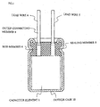
- An electrolytic capacitor typically has such a structure shown in FIG.1 . That is, an anode electrode foil 2 is made of a band-shaped high purity aluminum foil where the effective aluminum foil surface has been enlarged through etching process chemically or electrochemically, and an oxide film is formed on the surface, through a chemical process of treating the aluminum foil with a chemical solution such as ammonium borate aqueous solution and the like.
- a cathode electrode foil 3 is also made of an etched aluminum foil of high purity.
- Capacitor element 1 is formed by the anode electrode foil 2 and the cathode electrode foil 3, wound together with intervening separator 11 made of manila paper and the like.
- the capacitor element 1 after impregnating with electrolyte solution for driving the electrolytic capacitors, is housed into a bottomed outer case 10 made of aluminum and the like.
- the outer case 10 is equipped at the opening with a sealing member 9 made of an elastic rubber, and is sealed by drawing.
- the anode electrode foil 2 and the cathode electrode foil 3 are each connected to lead wires 4 and 5, employed as electrode leading means to lead the electrodes, by means of stitching, ultrasonic welding, and the like, as shown in FIG.2 .
- Each of the lead wires 4 and 5 employed as electrode leading means is comprised of a rod member 6 made of aluminum, and a connecting member 7 that comes into contact with each of the electrode foils 2 and 3, and further an outside connecting member 8 made of solderable metal which has been fixed at the tip of the rod member 6.
- the electrolytic capacitor requires the withstand voltage characteristic of 28V and 84V and more. Furthermore, the electrolytic capacitors must withstand high temperature in this field, and a high temperature life characteristic is in demand.
- the electrolytic capacitor cannot cope with the low impedance characteristic as such. Moreover, although the withstand voltage of 28V is capable, the limit is 30V, and it cannot respond to the requirement of the high withstand voltage of 84V and more. Moreover, these electrolytic capacitors suffer from a problem that the moisture resistant characteristic is low despite of the fact that the moisture resistance of these electrolytic capacitors are in demand similar to the semiconductors.
- EP 1 394 824 A1 a document according to Article 54 (3) EPC, hence relevant for novelty, discloses an electrolytic capacitor according to the pre-characterizing portion of claim 1.
- the present invention aims to provide an electrolytic capacitor having a low impedance characteristic and a high withstand voltage characteristic of 100V class, and an excellent high temperature life characteristic and an excellent moisture resistant characteristic.
- Aluminum electrolytic capacitor has such a structure same as the conventional structure, as shown in FIGS. 1 and 2 .
- Capacitor element 1 is formed by an anode electrode foil 2 and a cathode electrode foil 3, wound together with intervening separator 11.
- lead wires 4 and 5 employed as the electrode leading means, are connected to the anode electrode foil 2 and the cathode electrode foil 3, respectively.
- the lead wires 4 and 5 are comprised of connecting members 7 that come into contact with both electrode foils; rod members 6 connected to the connecting members 7; and an outer connecting member 8 weld to the rod member 6. Further, each foil and lead wire is mechanically connected by means of stitching, ultrasonic welding, and the like.
- the anode electrode foil 2 used is one obtained in such a manner that an aluminum foil of a purity of 99% is subjected to chemical or electrochemical etching in an acidic solution to enhance the surface area thereof and then subjected to chemical treatment in an ammonium borate or ammonium adipate aqueous solution, so as to form an anode oxide film layer on the surface thereof.
- the capacitor element 1 impregnating with the electrolyte solution is housed in an aluminum cylindrical outer case 10 with a bottom, and a sealing member 9, having a perforation hole for guiding the lead wires 4 and 5, is inserted into an open end of the outer case 10, and further, the open end of the outer case 10 is sealed by drawing to seal the aluminum electrolytic capacitor.
- a separator of the present invention is made of heat-resistant synthetic resin.
- the separator include fabric, nonwoven fabric, paper, and porous film.
- the fabric, nonwoven fabric or paper made by using the high-molecular fibers such as polyester, polyamide, vinylon, rayon, aramid, poly ethylene terephthalate, polyethylene naphtahalate, poly phenylene sulfide, aromatic polyester, polyimide, polyamido-imido, polyetherimide, polytetrafluoroethylene, polyaminobismaleimide, poly(ethylene-tetraethylene), poly(vinylidene fluoride), and the like, or using the high porous film made by using these high molecules.
- resins used as binders include epoxy resin, phenol resin, polyurethene resin, and melamine resin. Due to the low tensile strength and low heat resistance nature of polypropylene, polyethylene and the like, winding of the capacitor element is going to be difficult using these and thus not preferable
- the electrolyte solution of the electrolytic capacitor used in the present invention contains an aluminum tetrafluoride salt.
- examples of this salt include an ammonium salt, an amine salt, a quaternary ammonium salt, or a quaternary cyclic amidinium ion as cation component, can be used.
- Examples of an amine constituting the amine salt include a primary amine (such as methylamine, ethylamine, propylamine, butylamine, ethylenediamine, monoethanolamine, and the like); secondary amine (such as dimethylamine, diethylamine, dipropylamine, ethy-methylamine, diphenylamine, diethanolamine and the like); and tertiary amine (such as trimethylamine, triethylamine, tributylamine, triethanolamine, and the like).
- a primary amine such as methylamine, ethylamine, propylamine, butylamine, ethylenediamine, monoethanolamine, and the like
- secondary amine such as dimethylamine, diethylamine, dipropylamine, ethy-methylamine, diphenylamine, diethanolamine and the like
- tertiary amine such as trimethylamine, triethylamine, tributylamine, triethanolamine,
- Examples of a quaternary ammonium constituting the quaternary ammonium salt include a tetraalkylammonium (such as tetramethylammonium, tetraethylammonium, tetrapropylammonium, tetrabutylammonium, methyltriethylammonium, di-methyldiethylammonium and the like) and a pyridinium (such as 1-methylpyridinium, 1-ethylpyridinium, 1,3-diethylpyridinium and the like).
- a tetraalkylammonium such as tetramethylammonium, tetraethylammonium, tetrapropylammonium, tetrabutylammonium, methyltriethylammonium, di-methyldiethylammonium and the like
- a pyridinium such as 1-methylpyridinium, 1-ethy
- the quaternized cyclic amidinium ion is a cation formed by quaternized a cyclic compound having an N,N,N'-substituted amidine group, and the following compounds are exemplified as the cyclic compound having an N,N,N'-substituted amidine group.
- imidazole monocyclic compound for example, an imidazole homologue, such as 1-methylimidazole, 1-phenylimidazole, 1,2-dimethyl-imidazole, 1-ethyl-2-methylimidazole, 2-ethyl-1-methylimidazole, 1,2-diethylimidazole, 1,2,4-trimethylimidazole and the like, an oxyalkyl derivative, such as 1-methyl-2-oxymethylimidazole, 1-methyl-2-oxyethyl-imidazole, and the like, a nitro derivative such as 1-methyl-4(5)-nitroimidazole, and the like, and an amino derivative such as 1,2-dimethyl-5(4)-aminoimidazole, and the like), a benzoimidazole compound (such as 1-methylbenzoimidazole, 1-methyl-2-benzylbenzoimidazole, 1-methyl-5(6)-nitrobenzo-imidazole and the like), a compound having a 2-imidazoline ring (
- the solvent in use for electrolyte solution according to the present invention comprises a polar protic solvent, a polar aprotic solvent, and their mixture thereof.
- the polar protic solvent include monohydric alcohols (such as ethanol, propanol, butanol, pentanol, hexanol, cyclo-butanol, cyclo-pentanol, cyclo-hexanol, benzyl alcohol, and the like); and polyhydric alcohol and oxy alcohol compounds (such as ethylene glycol, propylene glycol, glycerine, methyl cellosolve, ethyle cellosolve, methoxy propylene glycol, dimethoxy propanol, and the like).
- aprotic polar solvent examples include amide series (such as N-methylformamide, N,N-dimethylformamide, N-ethylformamide, N,N-diethylformamide, N-methyl acetamide, N,N-dimethyl acetamide, N-ethyl acetamide, N,N-diethyl acetamide, hexamethylphosphoric amide, and the like); lactone compounds (such as ⁇ -butyrolactone, ⁇ -valerolactone, ⁇ -valerolactone, and the like); sulfolane series (such as sulfolane, 3-methyl sulfolane, 2,4-dimethyl sulfolane, and the like); cyclic amide compounds (such as N-methyl-2-pyrrolidone, and the like); carbonates (such as ethylene carbonate, propylene carbonate, isobutylene carbonate, and the like); nitrile compound (such as N-methylform
- ⁇ -butyrolactone is preferably used because the impedance characteristic improves.
- Sulfolane, 3-methyl sulfolane, and 2,4-dimethyl sulfolane are preferably used because the high temperature characteristic improves.
- Ethylene glycol is preferably used because the withstand voltage characteristic improves.
- the electrolyte solution containing aluminum tetrafluoride salt is used in the electrolytic capacitor of the present invention.
- the electrolytic capacitor of the present invention has a low impedance characteristic, and a high temperature withstand voltage characteristic. Because the separator in use is made of heat resistant synthetic resin, moisture from the separator is less likely to be mixed into the electrolyte solution, so that the electrolytic capacitor has the excellent high temperature life characteristic. That is to say, in case of using a separator from the conventional manila paper and the like, the moisture is generated from the separator, and the reactivity of the electrolyte solution used in the present invention with the electrode foil gets large to influence the life characteristic. However, in the present invention, such moisture generation is controlled to obtain an excellent high temperature life characteristic. Furthermore, the moisture resistance characteristic is excellent.
- a first electrolytic capacitor of the present invention described above has the low impedance characteristic and the high withstand voltage characteristic of 100V class, wherein the electrolytic capacitor provides the excellent high temperature life characteristic and the excellent moisture resistance characteristic.
- the electrolytic capacitor of the present invention comprises a capacitor element fabricated by winding an anode foil and a cathode foil via a separator is impregnated with electrolyte solution, an outer case for housing the capacitor element, a sealing member for sealing an open part of the outer case, wherein the electrolyte solution in use contains an aluminum tetrafluoride salt, and wherein the separator in use is a mixed paper containing glass fiber.
- the electrolytic capacitor has the same structure as the first electrolytic capacitor.
- separator a mixed paper containing glass fiber is used in the present invention.
- the mixed fibers include pulp fiber used in papers such as manila paper, craft paper and the like; and the synthetic fibers such as polyester fiber, polyethylene fiber, polypropylene fiber, polytetrafluoroethylene fiber, polyamido fiber, and the like.
- the separator made only from glass fiber a thickness of the separator increases, and the impedance of electrolytic capacitor gets large. The effectiveness of the electrolytic capacitor of the present invention is not obtainable by using this.
- the electrolyte solution containing aluminum tetrafluoride salt is used in the electrolytic capacitor of the present invention.
- the electrolytic capacitor of the present invention has a low impedance characteristic and a high temperature withstand voltage characteristic. Because the separator in use is made of mixed paper containing glass fiber, the moisture from the separator is less likely to be mixed into the electrolyte solution, so that the electrolytic capacitor has the excellent high temperature life characteristic. That is to say, in case of using a separator made from the conventional manila paper and the like, the moisture is generated from the separator, and the reactivity of the electrolyte solution used in the present invention with the electrode foil gets large to influence the life characteristic. However, such the present invention, the moisture generation is controlled to obtain an excellent high temperature life characteristic. Furthermore, the moisture resistance characteristic is excellent.
- the second electrolytic capacitor of the present invention described above has the low impedance characteristic, the high withstand voltage characteristic of 100V class, and the excellent moisture resistance characteristic.
- the electrode foil subjected to phosphate treatment is used as the electrode foils.
- the present invention is still effective by using the electrode foil subjected to phosphate treatment as one of the cathode electrode foil and the anode electrode foil. Dcterioration of both foils is prevented if this is applied to both foils so normally both foils are subjected to phosphate treatment.
- the aluminum foil of high purity is subjected to chemical or electrochemical etching to obtain the etching foil
- the electrode foil of the present invention the etching foil obtained by performing the phosphate aqueous solution impregnation process before, during, or after the etching process is used as the cathode electrode foil.
- the etching foil the etching foil untreated with phosphate is subjected to phosphate synthesis, or the electrode foil that performed the phosphate impregnation process before, during, or after the chemical treatment is used.
- the effect of the present invention improves by adding the phosphorous compounds to the electrolyte solution of the electrolytic capacitor described above.
- phosphorus compounds and salts thereof include orthophosphoric acid, phosphonous acid, hypophosphorus acid and their salts.
- salts of the phosphorus compounds an ammonium salt, an aluminum salt, a sodium salt, a calcium salt, and a potassium salt can be used.
- examples of phosphorous compound include ethyl phosphate, diethyl phosphate, butyl phosphate, dibutyl phosphate and the like; and phosphonate such as 1-hydroxyethylidene-1,1-diphosphonic acid, aminotrimethylene phosphonic acid, phenyl phosphonic acid, and the like.
- examples of phosphinate include methyl phosphinate, butyl phosphinate, and the like.
- condensed phosphates include straight-chain condensed phosphates such as pyrophosphoric acid, tripolyphosphoric acid, tetrapolyphosphoric acid, and the like; cyclic condensed phosphates such as metaphosphate, hexametaphosphate, and the like, or the combination of the chain condensed phosphate and cyclic condensed phosphate.
- salts of these condensates an ammonium salt, an aluminum salt, a sodium salt, a calcium salt, a potassium salt, and the like can be used.
- the addition amount is ranging from 0.05 to 3% by weight, and preferably is ranging from 0.1 to 2% by weight.
- the electrolytic capacitor of the present invention described above has the low impedance characteristic and the high withstand voltage of 100V class, and the excellent high temperature life characteristic.
- the electrolytic capacitor of the present invention utilizes the electrode foil subjected to phosphate treatment, the reaction of the electrode foil with the electrolyte solution is controlled, whereby the high temperature life characteristic is stabilized.
- a partial cross-linking peroxide butyl rubber that added peroxide as cross-linking agent to a butyl rubber polymer comprised of isobutylene, isoprene, and divinylbenzene copolymer is used as the sealing member.
- vulcanizing agents used in the vulcanization of peroxides include ketone peroxides, peroxy ketals, hydro-peroxides, dialkyl peroxides, diacyl peroxides, peroxy dicarbonates, peroxy esters, and the like.
- the electrolytic capacitor of the present invention a partial cross-linking peroxide butyl rubber that added peroxide as cross-linking agent to a butyl rubber polymer comprised of isobutylene, isoprene, and divinylbenzene copolymer is used as the sealing member.
- the electrolyte solution containing the aluminum tetrafluoride salt is used.
- the electrolytic capacitor of the present invention has a low impedance characteristic, and a high withstand voltage characteristic of 100V class. The high temperature life characteristic is improved further by the excellent high temperature characteristics of the electrolyte solution and the sealing member of the present invention.
- the quaternary cyclic amidinium compound tends to cause leakage due to the reaction with the hydroxyl ion generated in the vicinity of the cathode leading means, however, the electrolyte solution used in the present invention seemingly has a less reactivity with the hydroxyl ion, and owing to the excellent sealability between the perforation hole of the sealing member and the lead wire, the leakage characteristic is further improved by these synergistic effects.
- the electrolytic capacitor of the present invention has the same structure as that of the conventional ones.
- the present invention is explained by referring to FIGS. 1 and 2 .
- a capacitor element 1 is formed by winding an anode electrode foil 2 and a cathode electrode foil 3 via a separator 11.
- the anode electrode foil 2 and the cathode electrode foil 3 are connected respectively to a lead wire 4 for leading the anode electrode and an another lead wire 5 for leading the cathode electrode.
- These lead wires 4 and 5 are composed of connecting members 7 being in contact with the electrode foils, the rod members 6 having been molded integrally with the connecting members 7, and outer connecting members 8 having been fixed at the tip of the rod members 6.
- the connecting member 7 and the rod member 6 are made from aluminum of 99% purity while the outer connecting member 8 is made of a copper-plated steel wire (hereinafter CP wire).
- CP wire copper-plated steel wire
- These lead wires 4 and 5 are connected respectively to the electrode foils 2 and 3 at the connecting members 7 by means of stitching, ultrasonic welding, and the like.
- the anode electrode foil 2 is made of an aluminum foil of 99.9% purity in an acidic solution thereby enlarging the surface area thereof through the chemical or electrochemical etching process, and then subjecting the aluminum foil to a chemical treatment in an ammonium adipate aqueous solution, to thereby form an anode oxidation film on the surface thereof.
- the capacitor element 1, which impregnates the electrolyte solution, is then housed into a bottomed outer case 10 made of aluminum.
- the outer case 10 is provided at the opening with a sealing member 9 and then sealed by drawing.
- the sealing member 9 is made of, for example, an elastic rubber such as butyl rubber, and the like, and has perforation holes through which the lead wires 4 and 5 are to be passed.
- separator in use includes a separator composed of poly ethylene terephthalate (PET), and a conventionally used separator made of manila paper.
- PET poly ethylene terephthalate
- the electrolyte solution A containing 75% by weight of ⁇ -butyrolactone as solvent and 25% by weight of 1-ethyl-2,3-dimethylimidazolinium aluminum tetrafluoride salt as solute is used.
- the electrolyte solution B containing 80% by weight of ⁇ -butyrolactone as solvent and 20% by weight of 1-ethyl-2,3-dimethylimidazolinium aluminum tetrafluoride salt as solute is used.
- electrolyte solution C containing 75% by weight of ⁇ -butyrolactone as solvent and 1-ethyl-2,3-dimethylimidazolinium hydrogen phthalate salt as solute is used as the electrolyte solution containing conventionally used electrolyte.
- the rated voltages of the electrolytic capacitors using the electrolyte solutions A and C are 16V, and that of using the electrolyte solution B is 100V.
- the characteristics of the electrolytic capacitors are evaluated.
- the test condition is 125°C at 2,000 hours in the loaded state, and 105oC at 2,000 hours in the unloaded state. The results are shown in (Table 1-1) to (Table 1-4).
- the electrolytic capacitor of the first embodiment has the excellent high temperature life characteristics, a low dielectric loss coefficient (tan ⁇ ), and a less change in the dielectric loss coefficient (tan ⁇ ) at 125oC, compared with the electrolytic capacitor of the comparative examples 1 and 2. Furthermore, (Table 1-3) and (Table 1-4) clearly show the excellent life characteristics and initial characteristics of the rated voltage 100V, to implement the 100V class electrolytic capacitor having a low impedance characteristic not found in the conventional ones.
- the electrolytic capacitor of the present invention have the excellent characteristics in the change in electrostatic capacity and the dielectric loss coefficient.
- the moisture resistance characteristic of the electrolytic capacitor of the present invention has improved.
- This electrolytic capacitor has the same structure as that of the first electrolytic capacitor, and the contents of characteristic evaluation which are also the same.
- separator in use include a separator composed of mixed paper containing glass fiber and a conventionally used separator made of manila paper. The results are shown in (Table 2-1) and (Table 2-4).
- the electrolytic capacitor of this embodiment has excellent high temperature life characteristics, a less change in dielectric loss coefficient (tan ⁇ ) of 125°C, and a low dielectric loss coefficient (tan ⁇ ), compared with the electrolytic capacitor of the comparative example. Furthermore, (Table 2-3) and (Table 2-4) clearly show the excellent life characteristics and initial characteristics of the rated voltage 100V, to implement the 100V class electrolytic capacitor having the low impedance characteristic not found in the conventional ones.
- the electrolytic capacitor of the present invention have the excellent characteristics in the change in electrostatic capacity and the dielectric loss coefficient.
- the moisture resistance characteristic of the electrolytic capacitor of the present invention has improved.
- first second third electrolytic capacitors in case of using an electrode foil subjected to phosphate treatment as the anode electrode foil and the cathode electrode foil, the high temperature life characteristic improved further.
- the high temperature life characteristic also improves by adding phosphorous compound to the electrolyte solution.
- a partial cross-linking peroxide butyl rubber that added peroxide as cross-linking agent to a butyl rubber polymer comprised of isobutylene, isoprene, and divinylbenzene copolymer Namely, the present invention achieves an extremely remarkable effect of preventing liquid leakage.
- the electrolyte solution containing the aluminum tetrafluoride salt is used.
- separator in use include a separator composed of heat resistant synthetic resin or a mixed paper containing glass fiber.
Landscapes
- Engineering & Computer Science (AREA)
- Power Engineering (AREA)
- Chemical & Material Sciences (AREA)
- Chemical Kinetics & Catalysis (AREA)
- Electrochemistry (AREA)
- Microelectronics & Electronic Packaging (AREA)
- Health & Medical Sciences (AREA)
- Medicinal Chemistry (AREA)
- Life Sciences & Earth Sciences (AREA)
- General Chemical & Material Sciences (AREA)
- Communicable Diseases (AREA)
- Nuclear Medicine, Radiotherapy & Molecular Imaging (AREA)
- Organic Chemistry (AREA)
- Pharmacology & Pharmacy (AREA)
- Oncology (AREA)
- Animal Behavior & Ethology (AREA)
- General Health & Medical Sciences (AREA)
- Public Health (AREA)
- Veterinary Medicine (AREA)
- Electric Double-Layer Capacitors Or The Like (AREA)
- Cell Separators (AREA)
Claims (3)
- Elektrolytkondensator mit einem Kondensatorelement (1), das durch Wickeln einer Anodenfolie (2), einer Kathodenfolie (3) und eines Separators (11) und Tränken mit einer Elektrolytlösung gefertigt wird, mit einem Außengehäuse (10) zur Aufnahme des Kondensatorelements (1) und mit einem Abdichtungsbauteil (9) zum Abdichten eines offenen Teils des Außengehäuses (10), wobei eine Aluminiumtetrafluorid-Salz enthaltende Elektrolytlösung als Elektrolytlösung verwendet wird, und wobei der Separator aus einem wärmebeständigen Kunstharz hergestellt ist,
dadurch gekennzeichnet, dass das wärmebeständige Kunstharz Polyester, Polyamid, Vinylon, Rayon, Aramid, Polyethylenterephthalat, Polyethylennaphtahalat, Polyphenylensulfid, aromatisches Polyester, Polyimid, Polyamido-Imido, Polyetherimid, Polytetrafluorethylen, Polyaminobismaleimid, Poly(ethylen-tetraethylen), Poly(vinylidenfluorid), oder eine beliebige Kombination davon ist. - Elektrolytkondensator nach Anspruch 1, wobei eine Elektrodenfolie, die einer Phosphatbehandlung unterzogen wird, als die Anodenelektrodenfolie (2) oder die Kathodenelektrodenfolie (3) verwendet wird.
- Elektrolytkondensator nach Anspruch 1, wobei ein teilweise vernetzender Peroxid-Butylgummi Peroxid als Vernetzungsmittel zu einem Butylgummipolymer hinzufügt, das ein Isobutylen-, Isopren-Copolymer enthält, und Divinylbenzen als Abdichtungsbauteil (9) verwendet wird.
Applications Claiming Priority (9)
| Application Number | Priority Date | Filing Date | Title |
|---|---|---|---|
| JP2002326028 | 2002-11-08 | ||
| JP2002326019A JP2004165209A (ja) | 2002-11-08 | 2002-11-08 | 電解コンデンサ |
| JP2002326019 | 2002-11-08 | ||
| JP2002326028A JP2004165213A (ja) | 2002-11-08 | 2002-11-08 | 電解コンデンサ |
| JP2002326720A JP2004165260A (ja) | 2002-11-11 | 2002-11-11 | 電解コンデンサ |
| JP2002326718 | 2002-11-11 | ||
| JP2002326718A JP2004165258A (ja) | 2002-11-11 | 2002-11-11 | 電解コンデンサ |
| JP2002326720 | 2002-11-11 | ||
| PCT/JP2003/014217 WO2004042758A1 (ja) | 2002-11-08 | 2003-11-07 | 電解コンデンサ |
Publications (3)
| Publication Number | Publication Date |
|---|---|
| EP1580774A1 EP1580774A1 (de) | 2005-09-28 |
| EP1580774A4 EP1580774A4 (de) | 2006-01-11 |
| EP1580774B1 true EP1580774B1 (de) | 2014-04-09 |
Family
ID=32314932
Family Applications (1)
| Application Number | Title | Priority Date | Filing Date |
|---|---|---|---|
| EP03810664.7A Expired - Lifetime EP1580774B1 (de) | 2002-11-08 | 2003-11-07 | Elektrolytkondensator |
Country Status (5)
| Country | Link |
|---|---|
| US (1) | US20060152882A1 (de) |
| EP (1) | EP1580774B1 (de) |
| KR (1) | KR101112023B1 (de) |
| TW (1) | TWI319586B (de) |
| WO (1) | WO2004042758A1 (de) |
Families Citing this family (7)
| Publication number | Priority date | Publication date | Assignee | Title |
|---|---|---|---|---|
| US7430108B2 (en) * | 2002-11-08 | 2008-09-30 | Nippon Chemi-Con Corporation | Electrolyte for electrolytic capacitor and electrolytic capacitor containing the same |
| KR100845802B1 (ko) * | 2006-10-18 | 2008-07-16 | 주식회사 디지털텍 | 합성섬유 전해지를 사용하는 알루미늄 전해 고분자콘덴서의 제조 방법 |
| KR100783736B1 (ko) * | 2006-10-18 | 2007-12-07 | 주식회사 디지털텍 | 권취형 알루미늄 전해 고분자 콘덴서 및 이의 제조 방법 |
| CN103891013B (zh) * | 2011-10-29 | 2016-11-09 | 日本贵弥功株式会社 | 电极材料的制造方法 |
| KR101671975B1 (ko) | 2014-04-16 | 2016-11-03 | 가부시키가이샤 티비케이 | 공진 모터 시스템 |
| JPWO2016035163A1 (ja) * | 2014-09-03 | 2017-06-15 | 株式会社Tbk | リターダの電磁コイル |
| JP7245990B2 (ja) * | 2018-03-30 | 2023-03-27 | パナソニックIpマネジメント株式会社 | 電解コンデンサの製造方法 |
Family Cites Families (22)
| Publication number | Priority date | Publication date | Assignee | Title |
|---|---|---|---|---|
| US3415687A (en) * | 1966-03-29 | 1968-12-10 | Honeywell Inc | Electric current producing cell |
| US3536963A (en) * | 1968-05-29 | 1970-10-27 | Standard Oil Co | Electrolytic capacitor having carbon paste electrodes |
| US3656027A (en) * | 1970-12-28 | 1972-04-11 | Standard Oil Co Ohio | Electrical capacitor having electrically-conductive, impervious connector |
| US3648126A (en) * | 1970-12-28 | 1972-03-07 | Standard Oil Co Ohio | Electrical capacitor employing paste electrodes |
| USRE31743E (en) * | 1980-09-15 | 1984-11-20 | Sprague Electric Company | AC Etching of aluminum capacitor foil |
| US4605989A (en) * | 1985-08-12 | 1986-08-12 | The Standard Oil Company | Electrodes for double layer capacitors |
| JPH0458508A (ja) * | 1990-06-28 | 1992-02-25 | Nippon Chemicon Corp | 電解コンデンサ |
| JP2965335B2 (ja) * | 1990-08-09 | 1999-10-18 | 日本ケミコン株式会社 | 電解コンデンサ |
| EP0684620B1 (de) * | 1993-12-03 | 2003-06-04 | Sanyo Chemical Industries, Ltd. | Elektrolytloesung und daraus hergestelltes elektrochemisches element |
| JP3555630B2 (ja) * | 1995-03-17 | 2004-08-18 | 日本ケミコン株式会社 | 電解コンデンサ |
| JP3220620B2 (ja) * | 1995-05-26 | 2001-10-22 | 松下電器産業株式会社 | アルミ電解コンデンサ |
| JPH10116629A (ja) * | 1996-10-15 | 1998-05-06 | Mitsui Chem Inc | 非水電解液 |
| JPH1167600A (ja) * | 1997-08-25 | 1999-03-09 | Nippon Chemicon Corp | 電解コンデンサ |
| JPH11283874A (ja) * | 1998-01-28 | 1999-10-15 | Matsushita Electric Ind Co Ltd | 電解コンデンサ |
| JPH11265839A (ja) * | 1998-03-17 | 1999-09-28 | Matsushita Electric Ind Co Ltd | アルミニウム電解コンデンサ |
| DE19850826A1 (de) * | 1998-11-04 | 2000-05-11 | Basf Ag | Als Separatoren in elektrochemischen Zellen geeignete Verbundkörper |
| EP1139356A4 (de) * | 1999-09-13 | 2005-11-30 | Asahi Glass Co Ltd | Elektrischer doppelschichtkondensator |
| JP4808358B2 (ja) * | 2001-05-11 | 2011-11-02 | 三菱化学株式会社 | 電解コンデンサ用電解液及びそれを用いた電解コンデンサ |
| CN100394522C (zh) * | 2001-05-11 | 2008-06-11 | 三菱化学株式会社 | 电解电容器用电解液及使用该电解液的电解电容器 |
| US6459565B1 (en) * | 2001-06-11 | 2002-10-01 | Kemet Electronics Corporation | Surface mount aluminum capacitor having anode foil anodized in an aqueous phosphate solution |
| DE10141410B4 (de) * | 2001-08-23 | 2007-10-11 | Johns Manville Europe Gmbh | Batterieseparatoren, Verfahren zu deren Herstellung sowie die Verwendung derselben |
| EP1580772B1 (de) * | 2002-11-08 | 2015-03-11 | Nippon Chemi-Con Corporation | Elektrolytkondensator |
-
2003
- 2003-11-07 WO PCT/JP2003/014217 patent/WO2004042758A1/ja not_active Ceased
- 2003-11-07 US US10/534,212 patent/US20060152882A1/en not_active Abandoned
- 2003-11-07 TW TW092131327A patent/TWI319586B/zh not_active IP Right Cessation
- 2003-11-07 EP EP03810664.7A patent/EP1580774B1/de not_active Expired - Lifetime
- 2003-11-07 KR KR1020057007951A patent/KR101112023B1/ko not_active Expired - Fee Related
Also Published As
| Publication number | Publication date |
|---|---|
| US20060152882A1 (en) | 2006-07-13 |
| TW200421365A (en) | 2004-10-16 |
| TWI319586B (en) | 2010-01-11 |
| KR20050088285A (ko) | 2005-09-05 |
| KR101112023B1 (ko) | 2012-02-24 |
| WO2004042758A1 (ja) | 2004-05-21 |
| EP1580774A4 (de) | 2006-01-11 |
| EP1580774A1 (de) | 2005-09-28 |
Similar Documents
| Publication | Publication Date | Title |
|---|---|---|
| US7724501B2 (en) | Electrolytic capacitor | |
| US20080030926A1 (en) | Electrolytic capacitor | |
| KR100366551B1 (ko) | 전해콘덴서 | |
| KR100608466B1 (ko) | 전해캐패시터용전해질및이를포함하는전해캐패시터 | |
| US20120214049A1 (en) | Electronic component and method of manufacturing the same | |
| EP1580774B1 (de) | Elektrolytkondensator | |
| JP7813999B2 (ja) | 電解コンデンサおよびその製造方法 | |
| EP1580775B1 (de) | Elektrolytlösung für einen elektrolytkondensator und elektrolytkondensator damit | |
| CN100550238C (zh) | 电解电容器 | |
| CN100481286C (zh) | 电解电容器 | |
| EP1580776B1 (de) | Herstellungverfahen für elektrolytkondensatoren | |
| JPH07272979A (ja) | 電解コンデンサ | |
| JP4844185B2 (ja) | チップ型アルミ電解コンデンサの製造方法 | |
| JP2004304080A (ja) | 電解コンデンサ | |
| JP4493280B2 (ja) | 電解コンデンサ | |
| JP2004165213A (ja) | 電解コンデンサ | |
| JP2002299190A (ja) | 電解コンデンサ | |
| JP2001102261A (ja) | 電解コンデンサ |
Legal Events
| Date | Code | Title | Description |
|---|---|---|---|
| PUAI | Public reference made under article 153(3) epc to a published international application that has entered the european phase |
Free format text: ORIGINAL CODE: 0009012 |
|
| 17P | Request for examination filed |
Effective date: 20050519 |
|
| AK | Designated contracting states |
Kind code of ref document: A1 Designated state(s): DE FR GB |
|
| A4 | Supplementary search report drawn up and despatched |
Effective date: 20051130 |
|
| RIC1 | Information provided on ipc code assigned before grant |
Ipc: H01G 9/02 19680901ALI20051124BHEP Ipc: H01G 9/04 19680901ALI20051124BHEP Ipc: H01G 9/035 19950101AFI20040526BHEP Ipc: H01G 9/10 19680901ALI20051124BHEP Ipc: H01M 6/18 19740701ALI20051124BHEP |
|
| RAP1 | Party data changed (applicant data changed or rights of an application transferred) |
Owner name: NIPPON CHEMI-CON CORPORATION Owner name: MITSUBISHI CHEMICAL CORPORATION |
|
| 17Q | First examination report despatched |
Effective date: 20090722 |
|
| RAP1 | Party data changed (applicant data changed or rights of an application transferred) |
Owner name: MITSUBISHI CHEMICAL CORPORATION Owner name: NIPPON CHEMI-CON CORPORATION |
|
| GRAP | Despatch of communication of intention to grant a patent |
Free format text: ORIGINAL CODE: EPIDOSNIGR1 |
|
| INTG | Intention to grant announced |
Effective date: 20130812 |
|
| GRAP | Despatch of communication of intention to grant a patent |
Free format text: ORIGINAL CODE: EPIDOSNIGR1 |
|
| RIN1 | Information on inventor provided before grant (corrected) |
Inventor name: UE, MAKOTO Inventor name: TAKEDA, MASAYUKI Inventor name: OZAWA, MASASHI |
|
| INTG | Intention to grant announced |
Effective date: 20131218 |
|
| GRAS | Grant fee paid |
Free format text: ORIGINAL CODE: EPIDOSNIGR3 |
|
| GRAA | (expected) grant |
Free format text: ORIGINAL CODE: 0009210 |
|
| AK | Designated contracting states |
Kind code of ref document: B1 Designated state(s): DE FR GB |
|
| REG | Reference to a national code |
Ref country code: GB Ref legal event code: FG4D |
|
| REG | Reference to a national code |
Ref country code: DE Ref legal event code: R096 Ref document number: 60345993 Country of ref document: DE Effective date: 20140522 |
|
| REG | Reference to a national code |
Ref country code: DE Ref legal event code: R097 Ref document number: 60345993 Country of ref document: DE |
|
| PLBE | No opposition filed within time limit |
Free format text: ORIGINAL CODE: 0009261 |
|
| STAA | Information on the status of an ep patent application or granted ep patent |
Free format text: STATUS: NO OPPOSITION FILED WITHIN TIME LIMIT |
|
| 26N | No opposition filed |
Effective date: 20150112 |
|
| REG | Reference to a national code |
Ref country code: DE Ref legal event code: R097 Ref document number: 60345993 Country of ref document: DE Effective date: 20150112 |
|
| REG | Reference to a national code |
Ref country code: FR Ref legal event code: PLFP Year of fee payment: 13 |
|
| REG | Reference to a national code |
Ref country code: FR Ref legal event code: PLFP Year of fee payment: 14 |
|
| REG | Reference to a national code |
Ref country code: FR Ref legal event code: PLFP Year of fee payment: 15 |
|
| PGFP | Annual fee paid to national office [announced via postgrant information from national office to epo] |
Ref country code: FR Payment date: 20171124 Year of fee payment: 15 Ref country code: DE Payment date: 20171023 Year of fee payment: 15 |
|
| REG | Reference to a national code |
Ref country code: GB Ref legal event code: 732E Free format text: REGISTERED BETWEEN 20180118 AND 20180124 |
|
| PGFP | Annual fee paid to national office [announced via postgrant information from national office to epo] |
Ref country code: GB Payment date: 20171124 Year of fee payment: 15 |
|
| REG | Reference to a national code |
Ref country code: DE Ref legal event code: R082 Ref document number: 60345993 Country of ref document: DE Ref country code: DE Ref legal event code: R081 Ref document number: 60345993 Country of ref document: DE Owner name: NIPPON CHEMI-CON CORP., JP Free format text: FORMER OWNERS: NIPPON CHEMI-CON CORP., TOKIO, JP; MITSUBISHI CHEMICAL CORP., TOKIO/TOKYO, JP Ref country code: DE Ref legal event code: R081 Ref document number: 60345993 Country of ref document: DE Owner name: MITSUBISHI CHEMICAL CORPORATION, JP Free format text: FORMER OWNERS: NIPPON CHEMI-CON CORP., TOKIO, JP; MITSUBISHI CHEMICAL CORP., TOKIO/TOKYO, JP |
|
| REG | Reference to a national code |
Ref country code: DE Ref legal event code: R082 Ref document number: 60345993 Country of ref document: DE Ref country code: DE Ref legal event code: R081 Ref document number: 60345993 Country of ref document: DE Owner name: MITSUBISHI CHEMICAL CORPORATION, JP Free format text: FORMER OWNERS: MITSUBISHI RAYON CO., LTD., TOKIO/TOKYO, JP; NIPPON CHEMI-CON CORP., TOKYO, JP Ref country code: DE Ref legal event code: R081 Ref document number: 60345993 Country of ref document: DE Owner name: NIPPON CHEMI-CON CORP., JP Free format text: FORMER OWNERS: MITSUBISHI RAYON CO., LTD., TOKIO/TOKYO, JP; NIPPON CHEMI-CON CORP., TOKYO, JP |
|
| REG | Reference to a national code |
Ref country code: DE Ref legal event code: R119 Ref document number: 60345993 Country of ref document: DE |
|
| GBPC | Gb: european patent ceased through non-payment of renewal fee |
Effective date: 20181107 |
|
| PG25 | Lapsed in a contracting state [announced via postgrant information from national office to epo] |
Ref country code: FR Free format text: LAPSE BECAUSE OF NON-PAYMENT OF DUE FEES Effective date: 20181130 Ref country code: DE Free format text: LAPSE BECAUSE OF NON-PAYMENT OF DUE FEES Effective date: 20190601 |
|
| PG25 | Lapsed in a contracting state [announced via postgrant information from national office to epo] |
Ref country code: GB Free format text: LAPSE BECAUSE OF NON-PAYMENT OF DUE FEES Effective date: 20181107 |