EP1580506A1 - Verfahren und Vorrichtung zur Wasserstoffverflüssigung - Google Patents
Verfahren und Vorrichtung zur Wasserstoffverflüssigung Download PDFInfo
- Publication number
- EP1580506A1 EP1580506A1 EP05251729A EP05251729A EP1580506A1 EP 1580506 A1 EP1580506 A1 EP 1580506A1 EP 05251729 A EP05251729 A EP 05251729A EP 05251729 A EP05251729 A EP 05251729A EP 1580506 A1 EP1580506 A1 EP 1580506A1
- Authority
- EP
- European Patent Office
- Prior art keywords
- hydrogen
- gas
- cooled
- heat exchange
- produce
- Prior art date
- Legal status (The legal status is an assumption and is not a legal conclusion. Google has not performed a legal analysis and makes no representation as to the accuracy of the status listed.)
- Withdrawn
Links
- UFHFLCQGNIYNRP-UHFFFAOYSA-N Hydrogen Chemical compound [H][H] UFHFLCQGNIYNRP-UHFFFAOYSA-N 0.000 title claims abstract description 419
- 239000001257 hydrogen Substances 0.000 title claims abstract description 286
- 229910052739 hydrogen Inorganic materials 0.000 title claims abstract description 286
- 238000000034 method Methods 0.000 title claims abstract description 109
- 230000008569 process Effects 0.000 title claims abstract description 103
- 239000007789 gas Substances 0.000 claims abstract description 142
- 239000003949 liquefied natural gas Substances 0.000 claims abstract description 111
- VNWKTOKETHGBQD-UHFFFAOYSA-N methane Chemical compound C VNWKTOKETHGBQD-UHFFFAOYSA-N 0.000 claims abstract description 86
- 239000003507 refrigerant Substances 0.000 claims abstract description 73
- 239000007788 liquid Substances 0.000 claims abstract description 68
- 238000001816 cooling Methods 0.000 claims abstract description 56
- 239000003345 natural gas Substances 0.000 claims abstract description 36
- IJGRMHOSHXDMSA-UHFFFAOYSA-N Atomic nitrogen Chemical compound N#N IJGRMHOSHXDMSA-UHFFFAOYSA-N 0.000 claims abstract description 21
- 230000006835 compression Effects 0.000 claims description 27
- 238000007906 compression Methods 0.000 claims description 27
- 238000005057 refrigeration Methods 0.000 claims description 26
- 239000000203 mixture Substances 0.000 claims description 19
- 238000003860 storage Methods 0.000 claims description 10
- 238000010438 heat treatment Methods 0.000 claims description 8
- 239000001307 helium Substances 0.000 claims description 8
- 229910052734 helium Inorganic materials 0.000 claims description 8
- SWQJXJOGLNCZEY-UHFFFAOYSA-N helium atom Chemical compound [He] SWQJXJOGLNCZEY-UHFFFAOYSA-N 0.000 claims description 8
- 229910052754 neon Inorganic materials 0.000 claims description 7
- GKAOGPIIYCISHV-UHFFFAOYSA-N neon atom Chemical compound [Ne] GKAOGPIIYCISHV-UHFFFAOYSA-N 0.000 claims description 7
- 238000004064 recycling Methods 0.000 claims description 6
- 230000001419 dependent effect Effects 0.000 claims description 2
- 238000010792 warming Methods 0.000 claims description 2
- 229910052757 nitrogen Inorganic materials 0.000 abstract description 9
- 230000008901 benefit Effects 0.000 abstract description 6
- 239000000446 fuel Substances 0.000 description 22
- 238000006243 chemical reaction Methods 0.000 description 11
- 238000004519 manufacturing process Methods 0.000 description 8
- 239000004215 Carbon black (E152) Substances 0.000 description 7
- 239000003054 catalyst Substances 0.000 description 7
- 238000009826 distribution Methods 0.000 description 7
- 229930195733 hydrocarbon Natural products 0.000 description 7
- 150000002430 hydrocarbons Chemical class 0.000 description 7
- ATUOYWHBWRKTHZ-UHFFFAOYSA-N Propane Chemical compound CCC ATUOYWHBWRKTHZ-UHFFFAOYSA-N 0.000 description 6
- 230000003647 oxidation Effects 0.000 description 6
- 238000007254 oxidation reaction Methods 0.000 description 6
- WSFSSNUMVMOOMR-UHFFFAOYSA-N Formaldehyde Chemical compound O=C WSFSSNUMVMOOMR-UHFFFAOYSA-N 0.000 description 5
- 150000002431 hydrogen Chemical class 0.000 description 5
- 229920002866 paraformaldehyde Polymers 0.000 description 5
- 230000009467 reduction Effects 0.000 description 5
- MYMOFIZGZYHOMD-UHFFFAOYSA-N Dioxygen Chemical compound O=O MYMOFIZGZYHOMD-UHFFFAOYSA-N 0.000 description 3
- VNQABZCSYCTZMS-UHFFFAOYSA-N Orthoform Chemical compound COC(=O)C1=CC=C(O)C(N)=C1 VNQABZCSYCTZMS-UHFFFAOYSA-N 0.000 description 3
- 230000003197 catalytic effect Effects 0.000 description 3
- 239000002826 coolant Substances 0.000 description 3
- 229910001882 dioxygen Inorganic materials 0.000 description 3
- 238000005516 engineering process Methods 0.000 description 3
- 239000001294 propane Substances 0.000 description 3
- XLYOFNOQVPJJNP-UHFFFAOYSA-N water Substances O XLYOFNOQVPJJNP-UHFFFAOYSA-N 0.000 description 3
- QGZKDVFQNNGYKY-UHFFFAOYSA-N Ammonia Chemical compound N QGZKDVFQNNGYKY-UHFFFAOYSA-N 0.000 description 2
- UGFAIRIUMAVXCW-UHFFFAOYSA-N Carbon monoxide Chemical compound [O+]#[C-] UGFAIRIUMAVXCW-UHFFFAOYSA-N 0.000 description 2
- 229910002091 carbon monoxide Inorganic materials 0.000 description 2
- 238000002485 combustion reaction Methods 0.000 description 2
- 239000012809 cooling fluid Substances 0.000 description 2
- 239000000498 cooling water Substances 0.000 description 2
- 238000000151 deposition Methods 0.000 description 2
- 238000013461 design Methods 0.000 description 2
- 239000012530 fluid Substances 0.000 description 2
- 239000003502 gasoline Substances 0.000 description 2
- 239000012535 impurity Substances 0.000 description 2
- 238000000746 purification Methods 0.000 description 2
- 238000012546 transfer Methods 0.000 description 2
- 239000004411 aluminium Substances 0.000 description 1
- XAGFODPZIPBFFR-UHFFFAOYSA-N aluminium Chemical compound [Al] XAGFODPZIPBFFR-UHFFFAOYSA-N 0.000 description 1
- 229910052782 aluminium Inorganic materials 0.000 description 1
- 229910021529 ammonia Inorganic materials 0.000 description 1
- 238000004458 analytical method Methods 0.000 description 1
- QVGXLLKOCUKJST-UHFFFAOYSA-N atomic oxygen Chemical compound [O] QVGXLLKOCUKJST-UHFFFAOYSA-N 0.000 description 1
- 238000005094 computer simulation Methods 0.000 description 1
- 238000010924 continuous production Methods 0.000 description 1
- 238000004200 deflagration Methods 0.000 description 1
- 230000008021 deposition Effects 0.000 description 1
- 238000011161 development Methods 0.000 description 1
- 229910001873 dinitrogen Inorganic materials 0.000 description 1
- 230000000694 effects Effects 0.000 description 1
- 238000001704 evaporation Methods 0.000 description 1
- 238000004880 explosion Methods 0.000 description 1
- 239000002360 explosive Substances 0.000 description 1
- 238000009413 insulation Methods 0.000 description 1
- 238000011031 large-scale manufacturing process Methods 0.000 description 1
- 238000012986 modification Methods 0.000 description 1
- 230000004048 modification Effects 0.000 description 1
- 239000007800 oxidant agent Substances 0.000 description 1
- 230000001590 oxidative effect Effects 0.000 description 1
- 239000001301 oxygen Substances 0.000 description 1
- 229910052760 oxygen Inorganic materials 0.000 description 1
- 230000037361 pathway Effects 0.000 description 1
- JTJMJGYZQZDUJJ-UHFFFAOYSA-N phencyclidine Chemical compound C1CCCCN1C1(C=2C=CC=CC=2)CCCCC1 JTJMJGYZQZDUJJ-UHFFFAOYSA-N 0.000 description 1
- 230000000704 physical effect Effects 0.000 description 1
- 239000002760 rocket fuel Substances 0.000 description 1
- 230000008685 targeting Effects 0.000 description 1
- 238000009834 vaporization Methods 0.000 description 1
Images
Classifications
-
- F—MECHANICAL ENGINEERING; LIGHTING; HEATING; WEAPONS; BLASTING
- F25—REFRIGERATION OR COOLING; COMBINED HEATING AND REFRIGERATION SYSTEMS; HEAT PUMP SYSTEMS; MANUFACTURE OR STORAGE OF ICE; LIQUEFACTION SOLIDIFICATION OF GASES
- F25J—LIQUEFACTION, SOLIDIFICATION OR SEPARATION OF GASES OR GASEOUS OR LIQUEFIED GASEOUS MIXTURES BY PRESSURE AND COLD TREATMENT OR BY BRINGING THEM INTO THE SUPERCRITICAL STATE
- F25J1/00—Processes or apparatus for liquefying or solidifying gases or gaseous mixtures
- F25J1/003—Processes or apparatus for liquefying or solidifying gases or gaseous mixtures characterised by the kind of cold generation within the liquefaction unit for compensating heat leaks and liquid production
- F25J1/0032—Processes or apparatus for liquefying or solidifying gases or gaseous mixtures characterised by the kind of cold generation within the liquefaction unit for compensating heat leaks and liquid production using the feed stream itself or separated fractions from it, i.e. "internal refrigeration"
- F25J1/0042—Processes or apparatus for liquefying or solidifying gases or gaseous mixtures characterised by the kind of cold generation within the liquefaction unit for compensating heat leaks and liquid production using the feed stream itself or separated fractions from it, i.e. "internal refrigeration" by liquid expansion with extraction of work
-
- F—MECHANICAL ENGINEERING; LIGHTING; HEATING; WEAPONS; BLASTING
- F25—REFRIGERATION OR COOLING; COMBINED HEATING AND REFRIGERATION SYSTEMS; HEAT PUMP SYSTEMS; MANUFACTURE OR STORAGE OF ICE; LIQUEFACTION SOLIDIFICATION OF GASES
- F25J—LIQUEFACTION, SOLIDIFICATION OR SEPARATION OF GASES OR GASEOUS OR LIQUEFIED GASEOUS MIXTURES BY PRESSURE AND COLD TREATMENT OR BY BRINGING THEM INTO THE SUPERCRITICAL STATE
- F25J1/00—Processes or apparatus for liquefying or solidifying gases or gaseous mixtures
- F25J1/0002—Processes or apparatus for liquefying or solidifying gases or gaseous mixtures characterised by the fluid to be liquefied
- F25J1/0005—Light or noble gases
- F25J1/001—Hydrogen
-
- F—MECHANICAL ENGINEERING; LIGHTING; HEATING; WEAPONS; BLASTING
- F25—REFRIGERATION OR COOLING; COMBINED HEATING AND REFRIGERATION SYSTEMS; HEAT PUMP SYSTEMS; MANUFACTURE OR STORAGE OF ICE; LIQUEFACTION SOLIDIFICATION OF GASES
- F25J—LIQUEFACTION, SOLIDIFICATION OR SEPARATION OF GASES OR GASEOUS OR LIQUEFIED GASEOUS MIXTURES BY PRESSURE AND COLD TREATMENT OR BY BRINGING THEM INTO THE SUPERCRITICAL STATE
- F25J1/00—Processes or apparatus for liquefying or solidifying gases or gaseous mixtures
- F25J1/003—Processes or apparatus for liquefying or solidifying gases or gaseous mixtures characterised by the kind of cold generation within the liquefaction unit for compensating heat leaks and liquid production
- F25J1/0032—Processes or apparatus for liquefying or solidifying gases or gaseous mixtures characterised by the kind of cold generation within the liquefaction unit for compensating heat leaks and liquid production using the feed stream itself or separated fractions from it, i.e. "internal refrigeration"
- F25J1/0035—Processes or apparatus for liquefying or solidifying gases or gaseous mixtures characterised by the kind of cold generation within the liquefaction unit for compensating heat leaks and liquid production using the feed stream itself or separated fractions from it, i.e. "internal refrigeration" by gas expansion with extraction of work
- F25J1/0037—Processes or apparatus for liquefying or solidifying gases or gaseous mixtures characterised by the kind of cold generation within the liquefaction unit for compensating heat leaks and liquid production using the feed stream itself or separated fractions from it, i.e. "internal refrigeration" by gas expansion with extraction of work of a return stream
-
- F—MECHANICAL ENGINEERING; LIGHTING; HEATING; WEAPONS; BLASTING
- F25—REFRIGERATION OR COOLING; COMBINED HEATING AND REFRIGERATION SYSTEMS; HEAT PUMP SYSTEMS; MANUFACTURE OR STORAGE OF ICE; LIQUEFACTION SOLIDIFICATION OF GASES
- F25J—LIQUEFACTION, SOLIDIFICATION OR SEPARATION OF GASES OR GASEOUS OR LIQUEFIED GASEOUS MIXTURES BY PRESSURE AND COLD TREATMENT OR BY BRINGING THEM INTO THE SUPERCRITICAL STATE
- F25J1/00—Processes or apparatus for liquefying or solidifying gases or gaseous mixtures
- F25J1/003—Processes or apparatus for liquefying or solidifying gases or gaseous mixtures characterised by the kind of cold generation within the liquefaction unit for compensating heat leaks and liquid production
- F25J1/0047—Processes or apparatus for liquefying or solidifying gases or gaseous mixtures characterised by the kind of cold generation within the liquefaction unit for compensating heat leaks and liquid production using an "external" refrigerant stream in a closed vapor compression cycle
- F25J1/005—Processes or apparatus for liquefying or solidifying gases or gaseous mixtures characterised by the kind of cold generation within the liquefaction unit for compensating heat leaks and liquid production using an "external" refrigerant stream in a closed vapor compression cycle by expansion of a gaseous refrigerant stream with extraction of work
-
- F—MECHANICAL ENGINEERING; LIGHTING; HEATING; WEAPONS; BLASTING
- F25—REFRIGERATION OR COOLING; COMBINED HEATING AND REFRIGERATION SYSTEMS; HEAT PUMP SYSTEMS; MANUFACTURE OR STORAGE OF ICE; LIQUEFACTION SOLIDIFICATION OF GASES
- F25J—LIQUEFACTION, SOLIDIFICATION OR SEPARATION OF GASES OR GASEOUS OR LIQUEFIED GASEOUS MIXTURES BY PRESSURE AND COLD TREATMENT OR BY BRINGING THEM INTO THE SUPERCRITICAL STATE
- F25J1/00—Processes or apparatus for liquefying or solidifying gases or gaseous mixtures
- F25J1/006—Processes or apparatus for liquefying or solidifying gases or gaseous mixtures characterised by the refrigerant fluid used
- F25J1/0062—Light or noble gases, mixtures thereof
- F25J1/0065—Helium
-
- F—MECHANICAL ENGINEERING; LIGHTING; HEATING; WEAPONS; BLASTING
- F25—REFRIGERATION OR COOLING; COMBINED HEATING AND REFRIGERATION SYSTEMS; HEAT PUMP SYSTEMS; MANUFACTURE OR STORAGE OF ICE; LIQUEFACTION SOLIDIFICATION OF GASES
- F25J—LIQUEFACTION, SOLIDIFICATION OR SEPARATION OF GASES OR GASEOUS OR LIQUEFIED GASEOUS MIXTURES BY PRESSURE AND COLD TREATMENT OR BY BRINGING THEM INTO THE SUPERCRITICAL STATE
- F25J1/00—Processes or apparatus for liquefying or solidifying gases or gaseous mixtures
- F25J1/006—Processes or apparatus for liquefying or solidifying gases or gaseous mixtures characterised by the refrigerant fluid used
- F25J1/0062—Light or noble gases, mixtures thereof
- F25J1/0067—Hydrogen
-
- F—MECHANICAL ENGINEERING; LIGHTING; HEATING; WEAPONS; BLASTING
- F25—REFRIGERATION OR COOLING; COMBINED HEATING AND REFRIGERATION SYSTEMS; HEAT PUMP SYSTEMS; MANUFACTURE OR STORAGE OF ICE; LIQUEFACTION SOLIDIFICATION OF GASES
- F25J—LIQUEFACTION, SOLIDIFICATION OR SEPARATION OF GASES OR GASEOUS OR LIQUEFIED GASEOUS MIXTURES BY PRESSURE AND COLD TREATMENT OR BY BRINGING THEM INTO THE SUPERCRITICAL STATE
- F25J1/00—Processes or apparatus for liquefying or solidifying gases or gaseous mixtures
- F25J1/006—Processes or apparatus for liquefying or solidifying gases or gaseous mixtures characterised by the refrigerant fluid used
- F25J1/007—Primary atmospheric gases, mixtures thereof
- F25J1/0072—Nitrogen
-
- F—MECHANICAL ENGINEERING; LIGHTING; HEATING; WEAPONS; BLASTING
- F25—REFRIGERATION OR COOLING; COMBINED HEATING AND REFRIGERATION SYSTEMS; HEAT PUMP SYSTEMS; MANUFACTURE OR STORAGE OF ICE; LIQUEFACTION SOLIDIFICATION OF GASES
- F25J—LIQUEFACTION, SOLIDIFICATION OR SEPARATION OF GASES OR GASEOUS OR LIQUEFIED GASEOUS MIXTURES BY PRESSURE AND COLD TREATMENT OR BY BRINGING THEM INTO THE SUPERCRITICAL STATE
- F25J1/00—Processes or apparatus for liquefying or solidifying gases or gaseous mixtures
- F25J1/02—Processes or apparatus for liquefying or solidifying gases or gaseous mixtures requiring the use of refrigeration, e.g. of helium or hydrogen ; Details and kind of the refrigeration system used; Integration with other units or processes; Controlling aspects of the process
- F25J1/0203—Processes or apparatus for liquefying or solidifying gases or gaseous mixtures requiring the use of refrigeration, e.g. of helium or hydrogen ; Details and kind of the refrigeration system used; Integration with other units or processes; Controlling aspects of the process using a single-component refrigerant [SCR] fluid in a closed vapor compression cycle
- F25J1/0204—Processes or apparatus for liquefying or solidifying gases or gaseous mixtures requiring the use of refrigeration, e.g. of helium or hydrogen ; Details and kind of the refrigeration system used; Integration with other units or processes; Controlling aspects of the process using a single-component refrigerant [SCR] fluid in a closed vapor compression cycle as a single flow SCR cycle
-
- F—MECHANICAL ENGINEERING; LIGHTING; HEATING; WEAPONS; BLASTING
- F25—REFRIGERATION OR COOLING; COMBINED HEATING AND REFRIGERATION SYSTEMS; HEAT PUMP SYSTEMS; MANUFACTURE OR STORAGE OF ICE; LIQUEFACTION SOLIDIFICATION OF GASES
- F25J—LIQUEFACTION, SOLIDIFICATION OR SEPARATION OF GASES OR GASEOUS OR LIQUEFIED GASEOUS MIXTURES BY PRESSURE AND COLD TREATMENT OR BY BRINGING THEM INTO THE SUPERCRITICAL STATE
- F25J1/00—Processes or apparatus for liquefying or solidifying gases or gaseous mixtures
- F25J1/02—Processes or apparatus for liquefying or solidifying gases or gaseous mixtures requiring the use of refrigeration, e.g. of helium or hydrogen ; Details and kind of the refrigeration system used; Integration with other units or processes; Controlling aspects of the process
- F25J1/0211—Processes or apparatus for liquefying or solidifying gases or gaseous mixtures requiring the use of refrigeration, e.g. of helium or hydrogen ; Details and kind of the refrigeration system used; Integration with other units or processes; Controlling aspects of the process using a multi-component refrigerant [MCR] fluid in a closed vapor compression cycle
- F25J1/0212—Processes or apparatus for liquefying or solidifying gases or gaseous mixtures requiring the use of refrigeration, e.g. of helium or hydrogen ; Details and kind of the refrigeration system used; Integration with other units or processes; Controlling aspects of the process using a multi-component refrigerant [MCR] fluid in a closed vapor compression cycle as a single flow MCR cycle
-
- F—MECHANICAL ENGINEERING; LIGHTING; HEATING; WEAPONS; BLASTING
- F25—REFRIGERATION OR COOLING; COMBINED HEATING AND REFRIGERATION SYSTEMS; HEAT PUMP SYSTEMS; MANUFACTURE OR STORAGE OF ICE; LIQUEFACTION SOLIDIFICATION OF GASES
- F25J—LIQUEFACTION, SOLIDIFICATION OR SEPARATION OF GASES OR GASEOUS OR LIQUEFIED GASEOUS MIXTURES BY PRESSURE AND COLD TREATMENT OR BY BRINGING THEM INTO THE SUPERCRITICAL STATE
- F25J1/00—Processes or apparatus for liquefying or solidifying gases or gaseous mixtures
- F25J1/02—Processes or apparatus for liquefying or solidifying gases or gaseous mixtures requiring the use of refrigeration, e.g. of helium or hydrogen ; Details and kind of the refrigeration system used; Integration with other units or processes; Controlling aspects of the process
- F25J1/0221—Processes or apparatus for liquefying or solidifying gases or gaseous mixtures requiring the use of refrigeration, e.g. of helium or hydrogen ; Details and kind of the refrigeration system used; Integration with other units or processes; Controlling aspects of the process using the cold stored in an external cryogenic component in an open refrigeration loop
- F25J1/0224—Processes or apparatus for liquefying or solidifying gases or gaseous mixtures requiring the use of refrigeration, e.g. of helium or hydrogen ; Details and kind of the refrigeration system used; Integration with other units or processes; Controlling aspects of the process using the cold stored in an external cryogenic component in an open refrigeration loop in combination with an internal quasi-closed refrigeration loop
-
- F—MECHANICAL ENGINEERING; LIGHTING; HEATING; WEAPONS; BLASTING
- F25—REFRIGERATION OR COOLING; COMBINED HEATING AND REFRIGERATION SYSTEMS; HEAT PUMP SYSTEMS; MANUFACTURE OR STORAGE OF ICE; LIQUEFACTION SOLIDIFICATION OF GASES
- F25J—LIQUEFACTION, SOLIDIFICATION OR SEPARATION OF GASES OR GASEOUS OR LIQUEFIED GASEOUS MIXTURES BY PRESSURE AND COLD TREATMENT OR BY BRINGING THEM INTO THE SUPERCRITICAL STATE
- F25J1/00—Processes or apparatus for liquefying or solidifying gases or gaseous mixtures
- F25J1/02—Processes or apparatus for liquefying or solidifying gases or gaseous mixtures requiring the use of refrigeration, e.g. of helium or hydrogen ; Details and kind of the refrigeration system used; Integration with other units or processes; Controlling aspects of the process
- F25J1/0243—Start-up or control of the process; Details of the apparatus used; Details of the refrigerant compression system used
- F25J1/0279—Compression of refrigerant or internal recycle fluid, e.g. kind of compressor, accumulator, suction drum etc.
- F25J1/0292—Refrigerant compression by cold or cryogenic suction of the refrigerant gas
-
- F—MECHANICAL ENGINEERING; LIGHTING; HEATING; WEAPONS; BLASTING
- F25—REFRIGERATION OR COOLING; COMBINED HEATING AND REFRIGERATION SYSTEMS; HEAT PUMP SYSTEMS; MANUFACTURE OR STORAGE OF ICE; LIQUEFACTION SOLIDIFICATION OF GASES
- F25J—LIQUEFACTION, SOLIDIFICATION OR SEPARATION OF GASES OR GASEOUS OR LIQUEFIED GASEOUS MIXTURES BY PRESSURE AND COLD TREATMENT OR BY BRINGING THEM INTO THE SUPERCRITICAL STATE
- F25J2210/00—Processes characterised by the type or other details of the feed stream
- F25J2210/62—Liquefied natural gas [LNG]; Natural gas liquids [NGL]; Liquefied petroleum gas [LPG]
-
- F—MECHANICAL ENGINEERING; LIGHTING; HEATING; WEAPONS; BLASTING
- F25—REFRIGERATION OR COOLING; COMBINED HEATING AND REFRIGERATION SYSTEMS; HEAT PUMP SYSTEMS; MANUFACTURE OR STORAGE OF ICE; LIQUEFACTION SOLIDIFICATION OF GASES
- F25J—LIQUEFACTION, SOLIDIFICATION OR SEPARATION OF GASES OR GASEOUS OR LIQUEFIED GASEOUS MIXTURES BY PRESSURE AND COLD TREATMENT OR BY BRINGING THEM INTO THE SUPERCRITICAL STATE
- F25J2215/00—Processes characterised by the type or other details of the product stream
- F25J2215/32—Neon
-
- F—MECHANICAL ENGINEERING; LIGHTING; HEATING; WEAPONS; BLASTING
- F25—REFRIGERATION OR COOLING; COMBINED HEATING AND REFRIGERATION SYSTEMS; HEAT PUMP SYSTEMS; MANUFACTURE OR STORAGE OF ICE; LIQUEFACTION SOLIDIFICATION OF GASES
- F25J—LIQUEFACTION, SOLIDIFICATION OR SEPARATION OF GASES OR GASEOUS OR LIQUEFIED GASEOUS MIXTURES BY PRESSURE AND COLD TREATMENT OR BY BRINGING THEM INTO THE SUPERCRITICAL STATE
- F25J2270/00—Refrigeration techniques used
- F25J2270/04—Internal refrigeration with work-producing gas expansion loop
- F25J2270/06—Internal refrigeration with work-producing gas expansion loop with multiple gas expansion loops
-
- F—MECHANICAL ENGINEERING; LIGHTING; HEATING; WEAPONS; BLASTING
- F25—REFRIGERATION OR COOLING; COMBINED HEATING AND REFRIGERATION SYSTEMS; HEAT PUMP SYSTEMS; MANUFACTURE OR STORAGE OF ICE; LIQUEFACTION SOLIDIFICATION OF GASES
- F25J—LIQUEFACTION, SOLIDIFICATION OR SEPARATION OF GASES OR GASEOUS OR LIQUEFIED GASEOUS MIXTURES BY PRESSURE AND COLD TREATMENT OR BY BRINGING THEM INTO THE SUPERCRITICAL STATE
- F25J2270/00—Refrigeration techniques used
- F25J2270/14—External refrigeration with work-producing gas expansion loop
- F25J2270/16—External refrigeration with work-producing gas expansion loop with mutliple gas expansion loops of the same refrigerant
Definitions
- the present invention relates to a process and apparatus for liquefying hydrogen gas.
- Such hydrogen-powered vehicles may convert the hydrogen fuel into energy using fuel cells or may use the hydrogen fuel in an internal combustion engine.
- Hydrogen fuel may be stored on board the vehicle in the form of high pressure gas (typically 20 to 80 MPa maximum working pressure).
- high pressure gas typically 20 to 80 MPa maximum working pressure.
- one serious problem involving the use of high pressure gaseous hydrogen fuel is the risk of a crash causing a rupture of the high pressure hydrogen storage vessel which might result in a sudden explosive pressure wave followed by an immediate deflagration fire.
- Liquid hydrogen can be raised to a high pressure, e.g. 30 to 80 MPa, using a single stage reciprocating pump followed by heating the pressurised liquid to ambient temperature. This process has lower capital and operating costs that a corresponding hydrogen gas compression system. Therefore, it is also more cost effective to provide pressurised liquid hydrogen as a source of ultra high pressure hydrogen gas at a refuelling station for vehicles running on pressurised hydrogen gas.
- liquid hydrogen was first carried out in the 1950s as a consequence of the demand for liquid hydrogen as rocket fuel. However, it was quickly apparent that liquid hydrogen could not be used economically as a fuel for road vehicles due to the high power consumption required during hydrogen liquefaction which results in prohibitively high production costs.
- a hydrogen liquefaction process typically involves two stages; an initial pre-cooling stage and a subsequent liquefaction stage.
- Hydrogen must be cooled below its upper Joule-Thomson inversion temperature, i.e. the point below which a gas cools when expanded, before it can be liquefied in a recuperative liquefaction cycle.
- this means that hydrogen must be cooled below about -150°C in a pre-cooling step before entering the liquefaction stage of the process.
- hydrogen gas is pre-cooled to below about -150°C by indirect heat exchange against vaporising liquid nitrogen and/or cold nitrogen gas streams.
- An example of such a known process is disclosed in US-A-3109725 (Flynn) in which hydrogen gas is pre-cooled by indirect heat exchange against liquid nitrogen in which hydrogen gas is dissolved.
- a further example is disclosed in US-A-4765813 (Gaumer, Jr. et al) in which hydrogen gas is pre-cooled using liquid nitrogen and then further cooled using a closed neon refrigeration cycle. Compression duty in the refrigeration cycle takes place at the warm end of the cycle.
- US-A-2983585 discloses a partial oxidation process in which methane is partially oxidized with oxygen to produce carbon monoxide and hydrogen gas.
- the partial oxidation process is integrated with a hydrogen liquefaction process in which hydrogen gas is pre-cooled by indirect heat exchange against liquid methane and subsequently further cooled against a closed external refrigerating cycle using liquid nitrogen (“LIN”) as the refrigerant.
- LIN liquid nitrogen
- the resultant methane is compressed at the warm end of the liquefaction process and then fed to the partial oxidation process.
- the resultant gaseous nitrogen is compressed at the warm end of the closed cycle before being condensed by indirect heat exchange with liquid methane and recycled. It is disclosed that the liquid methane could be replaced with liquefied natural gas (“LNG").
- US-A-3347055 discloses a process in which a gaseous hydrocarbon feedstock is reacted to produce hydrogen gas which is then liquefied in an integrated liquefaction cycle.
- the liquefaction cycle involves two closed refrigerant cycles, the first using hydrogen gas a refrigerant and the second using nitrogen. Compression for both refrigeration cycles takes place at the warm end of the cycles.
- the hydrogen to be liquefied is also cooled by indirect heat exchange against liquefied hydrocarbon feedstock gas thereby producing gaseous feedstock at 1 atm. (e.g. about 0.1 MPa) for use in the hydrogen production plant.
- the hydrocarbon feedstock may be natural gas.
- JP-A-2002/243360 discloses a process for producing liquid hydrogen in which hydrogen feed gas is pre-cooled by indirect heat exchange against a stream of pressurised LNG.
- the pre-cooled hydrogen gas is fed to a liquefier where it is further cooled by indirect heat exchange against both LIN and a refrigerant selected from hydrogen or helium.
- the further cooled hydrogen is then expanded to produce partially condensed hydrogen which is separated into liquid hydrogen, which is removed and stored, and hydrogen vapour which is recycled around the liquefier.
- Quack discloses ("Conceptual Design of a High Efficiency Large Capacity Hydrogen Liquefier”; Adv. Cryog. Eng., Proc. CEC, Madison 2001, AIP, Vol. 613, 255-263) a hydrogen liquefier cycle that, to the inventors knowledge, most accurately represents the best current technology projections for hydrogen liquefaction cycles. It should be noted that Quack uses efficiency figures for compressors and turbines that are not achievable at present but which are thought to be realistic for the future.
- this vapour compression refrigeration step may use a mixture of refrigerants or gas cycles with nitrogen, hydrogen or helium as refrigerant.
- the hydrogen gas at 73K (about -200°C) is then further cooled to 25K (about -248°C) by indirect heat exchange against a mixture of helium and neon.
- the further cooled hydrogen gas at 25K (about -248°C) is then work expanded to partially liquefy the hydrogen.
- the cycle uses ortho-para conversion catalyst optimally arranged at the cold end of the plant and assumes the usual optimal placement of heat exchangers and turbines in the hydrogen circuit at the cold end of the plant.
- Quack cycle One of the major features of the Quack cycle is that all of the main hydrogen compression, propane recycle compression and helium/neon recycle compression takes place with each compressor stage operating at close to ambient temperature using ambient temperature cooling systems to remove heat of compression such as cooling water or air cooling. There is, however, a small cold flash-gas compressor operating at the cold end of the heat exchanger.
- Compressors operating at the warm end of a cryogenic cycle are usually cooled using water or air as a coolant.
- the low molecular weight of hydrogen means that a very large number of stages of compression must be used if centrifugal compressors are specified and, likewise for a given expansion duty, a large number of centrifugal expansion stages will be required operating in series.
- the hydrogen compressors are often reciprocating units. Multiple stage compressors plus large recuperative heat exchangers will usually be used in the pre-cooling steps of the process.
- LNG is produced and stored in vast quantities in numerous locations around the world.
- Such storage facilities pressurise and heat LNG before supplying the resultant pressurised natural gas to pipelines for distribution to industry and homes.
- the inventors have realised that, by using the internal energy of pressurised LNG to provide part of the energy required to liquefy hydrogen, it is possible to efficiently convert this vast source of energy to effective power which appears as a power reduction in a hydrogen liquefaction process.
- pressurised LNG absorbs heat at low temperature liberated from a hydrogen liquefaction plant.
- LNG storage and distribution facilities pump LNG to high pressure, usually between from about 3 to about 10 MPa, and then heat the pressurised LNG using natural gas burners submerged in a water bath.
- the burners use a small portion, e.g. 1 to 2%, of the ambient temperature natural gas as a fuel to heat the remaining pressurised LNG to ambient temperature.
- pressurised LNG in intended to describe LNG a pressure greater than atmospheric pressure (e.g. greater than about 0.1 MPa).
- the pressurised LNG is at a pressure of at least 2 MPa and, more preferably, between from about 3 to 10 MPa.
- condensable hydrogen gas is intended to describe hydrogen gas under particular temperature and pressure conditions such that expansion of the gas at that point will at least partially condense the gas.
- the inventors have realised that reduction of the temperature of hydrogen feed gas to below the Joule-Thomson inversion temperature for hydrogen gas is possible by pre-cooling the hydrogen feed gas by indirect heat exchange against pressurised LNG.
- this inversion temperature is usually about -150°C.
- the pre-cooled hydrogen feed gas is at a temperature of -156°C and a pressure of 2.5 MPa.
- the total amount of pressurised LNG used in the present hydrogen liquefaction process is from about 10 to about 60 kg (LNG) per kg (liquid hydrogen) , for example from about 27 to about 37 kg (LNG) per kg (liquid hydrogen) .
- the hydrogen liquefaction process is integrated with an LNG facility producing pressurised LNG.
- the process may further comprise:
- the pressurised LNG is usually at a temperature of about -158°C. Not only is the pressurised LNG at a sufficiently low temperature and have sufficient refrigeration capacity to pre-cool hydrogen feed and to absorb heat of compression in the liquefaction process, but also the heating of pressurised LNG by indirect heat exchange against hydrogen reduces the amount of natural gas required for combustion to heat pressurised LNG to produce high pressure natural gas for supply to pipelines.
- the process further comprises:
- cryogenic is intended to include process steps in which warmed refrigerant is compressed at a temperature below ambient temperature, for example at a cryogenic temperature, e.g. below -50°C.
- the expression is intended to include processes where the compressor is located downstream of the cold end of the pre-cooling heat exchanger.
- the expression should include processes in which warmed refrigerant is compressed at an intermediate temperature, e.g. a temperature between the temperature limits of the cycle, and the heat of compression removed by a cryogenic coolant, e.g. a coolant at a temperature of below about -50°C, for example pressurised LNG at about -158°C.
- the heat generated by cold compression of the or at least one warmed refrigerant may be removed using pressurised LNG. Cooling during cold compression is preferably provided by indirect heat exchange against pressurised LNG. In preferred embodiments, the or at least one compressed refrigerant is cooled by indirect heat exchange against pressurised LNG. Preferred embodiments of the process involve the use of at least one pressurised LNG inter-cooled multiple stage compressor to carry out the cold compression. All of the heat of compression can be removed in the heated pressurised LNG.
- Pressurised natural gas is usually fed to supply pipelines at ambient temperature.
- the heated pressurised LNG produced by the present process may be too cold to be fed directly to such pipelines. Therefore, where the hydrogen liquefaction process is to be integrated with natural gas supply pipelines, the heated pressurised LNG is usually further heated to bring the temperature up to ambient before being fed to the pipeline system.
- the pre-cooling step can, at least in principle, be used in combination with any of the examples of steps for further cooling pre-cooled hydrogen feed gas and for expanding condensable hydrogen gas known in the art.
- the following is a general description of only some of the possible embodiments.
- any suitable refrigerant(s) may be used to further cool the pre-cooled hydrogen feed gas to produce condensable hydrogen gas.
- suitable refrigerants include molecular hydrogen, helium, neon, molecular nitrogen and mixtures thereof.
- the or at least one refrigerant comprises molecular hydrogen.
- the or each of the refrigerants is molecular hydrogen.
- a single refrigerant may be all that is required to provide the refrigeration duty necessary to further cool the pre-cooled hydrogen feed gas to produce condensable hydrogen gas.
- more than one refrigerant may be used to provide this refrigeration duty.
- at least one of the resultant warmed refrigerants may be cold compressed, cooled and recycled although it is preferred that each warmed refrigerant is processed in this way.
- the process further comprises:
- the refrigeration duty provided by the hydrogen vapour may not be sufficient to further cool the pre-cooled hydrogen feed gas to form the condensable hydrogen gas. In such cases, only a portion of the refrigeration duty required to produce condensable hydrogen gas from said pre-cooled hydrogen feed gas is provided by indirect heat exchange against at least a portion of said hydrogen vapour and at least one further refrigerant would be required.
- At least a portion of the hydrogen flash gas is cold compressed to produce compressed hydrogen flash gas and then at least a portion of said compressed hydrogen flash gas is cooled by indirect heat exchange against pressurised LNG to produce cooled, compressed hydrogen flash gas and pressurised natural gas.
- the process may further comprise:
- Such processes may further comprise:
- These processes may comprise cold compressing at least a portion of the resultant warmed expanded hydrogen gas to produce compressed hydrogen gas and cooling at least a portion of said compressed hydrogen gas by indirect heat exchange against pressurised LNG to produce cooled, compressed hydrogen gas and pressurised natural gas.
- both hydrogen flash gas and expanded hydrogen gas may be used together to provide the necessary refrigeration duty.
- the process may further comprise; combining said cooled, compressed hydrogen flash gas with said expanded hydrogen gas to produce combined hydrogen gas; cold compressing at least a portion of said combined hydrogen gas to produce compressed combined hydrogen gas; and cooling at least a portion of said compressed combined hydrogen gas by indirect heat exchange against pressurised LNG to produce cooled, compressed combined hydrogen gas and pressurised natural gas.
- a feature of preferred embodiments of the present invention is that the temperature of pre-cooled hydrogen feed gas entering the main heat exchanger of the hydrogen liquefier is about the same as the temperature of hydrogen flash gas and of warmed expanded hydrogen gas leaving the main heat exchanger, e.g. about -156°C.
- the hydrogen feed gas comprises hydrogen gas recycled from downstream within the liquefaction process.
- the hydrogen feed gas comprises at least one stream of fresh hydrogen gas combined with recycled hydrogen gas. Therefore, the recycled hydrogen gas will be at the same pressure as the fresh hydrogen gas.
- the hydrogen feed gas consists of at least one stream of fresh hydrogen gas.
- the pressure of the or at least one stream of fresh hydrogen gas may be the same or different from the pressure of the or at least one refrigerant.
- the or at least one refrigerant may be at a pressure of from about 1.5 to about 3 MPa, e.g. 2.5 MPa
- the hydrogen feed gas may be at a pressure either of from about 1.5 to about 3 MPa, e.g. 2.5 MPa, or of from about 8 to about 12 MPa, e.g. 10 MPa.
- the temperature of the hydrogen feed gas is usually from about 15°C to about 40°C, for example about 30°C or about ambient temperature, e.g. from about 15 to about 20°C.
- the pressure of the hydrogen feed gas is usually between about 0.1 to about 15 MPa and is preferably either in the range of from about 1.5 to about 3 MPa, e.g. about 2.5 MPa, or from about 8 to about 12 MPa, e.g. about 10 MPa.
- Suitable catalysts for the conversion of ortho hydrogen to para hydrogen will usually be provided at multiple temperature levels in the process including the final hydrogen liquefaction temperature.
- the liquefaction process may be designed so that substantially all of the liquid hydrogen production is in the para form.
- the heat exchange system may be designed so that, at each ortho-para conversion temperature level, all the heat liberated in the ortho-para conversion is absorbed by the warming refrigerant streams.
- Carbonaceous or hydrocarbon-containing fuel may be reacted with steam and/or an oxidant gas comprising molecular oxygen to produce carbon monoxide and hydrogen gas in catalytic or non-catalytic processes.
- This hydrogen gas preferably forms at least a portion of the hydrogen feed gas.
- the hydrocarbon-containing fuel may be reacted with steam in a steam-methane reformer, with air (or oxygen gas) in a partial oxidation reactor or with steam and air (or oxygen gas) in an autothermal reformer.
- the hydrogen gas produced by such a process may be stored and, if required, liquefied at a later date.
- the process to produce the hydrogen gas may be integrated with the present invention with the hydrogen gas being fed directly, after purification, into the present process.
- Steam methane reformers and autothermal reformers may produce hydrogen at a pressure of from about 1.5 to about 3 MPa, e.g. about 2.5 MPa.
- a Partial Oxidation Enhanced Heat Transfer Reformer (POX EHTR) may produce hydrogen gas at a pressure of from about 8 to about 12 MPa, e.g. about 10 MPa.
- POX EHTR Partial Oxidation Enhanced Heat Transfer Reformer
- the hydrocarbon containing fuel is usually natural gas which would be readily available if the liquefaction process is integrated with an LNG terminal.
- the hydrocarbon-containing fuel may be at least a portion of the natural gas produced by indirect heat exchange against the hydrogen gas feed.
- Hydrogen gas is usually purified to remove impurities that might solidify in the hydrogen liquefier before being pre-cooled. After pre-cooling, the pre-cooled hydrogen gas may be further purified as required.
- a particularly preferred embodiment is a process substantially as hereinbefore described with reference to the accompanying drawing.
- apparatus for liquefying hydrogen according to the process defined in the first aspect comprising:
- the apparatus may be adapted and/or constructed such as to enable operation of any of the embodiments of the process described above.
- the apparatus further comprises at least one source of pressurised LNG, for example, the or at least one pump in an LNG storage and distribution facility.
- the heat exchange means for the pre-cooling step can, at least in principle, be used in combination with apparatus for further cooling pre-cooled hydrogen feed gas and for expanding condensable hydrogen gas known in the art.
- apparatus for further cooling pre-cooled hydrogen feed gas and for expanding condensable hydrogen gas known in the art.
- the following is a general description of some of the possible embodiments.
- the apparatus may further comprise:
- the apparatus preferably further comprising means for recycling hydrogen gas refrigerant to form part of said hydrogen feed gas.
- the apparatus preferably further comprising:
- At least one of the heat exchange means is preferably a multi-stream plate fin heat exchanger.
- the pre-coolers are preferably high pressure aluminium plate-fin heat exchangers.
- the apparatus may further comprise heating means for heating at least a portion of said pressurised natural gas to about ambient temperature before said natural gas is fed to a supply pipeline.
- a temperature controlling means may be required on the heating means to control the natural gas discharge temperature.
- Flow control means such as a valve is usually used downstream of LNG terminal heaters to control the flow of pressurised LNG from the terminal to the hydrogen liquefier and to provide any necessary pressure drop in the process for the LNG flow.
- the cold compression means is preferably at least one multiple stage compressor inter-cooled with pressurised LNG.
- a preferred embodiment is apparatus substantially as hereinbefore described with reference to the accompanying drawing.
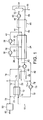
- a stream 10 of hydrogen feed gas is fed, at about 2.5 MPa and 30°C, to the inlet of a plate-fin heat exchanger 12 where it is pre-cooled against a stream 14 of high pressure LNG which may be taken from the discharge of the LNG pumps (not shown) in an LNG terminal (not shown) which supplies natural gas at high pressure to pipeline systems (not shown).
- the high pressure LNG is at a temperature of about -158°C and a pressure of about 40 MPa.
- the hydrogen feed gas stream 10 is formed from the combination of a stream 16 of fresh hydrogen gas which may be produced in an integrated hydrogen gas production process (not shown), and a stream 18 of compressed recycled hydrogen gas.
- the fresh hydrogen gas has been purified in a purification system (not shown) to remove impurities that might solidify during the hydrogen liquefaction process.
- the hydrogen feed gas is pre-cooled to produce a stream 20 of pre-cooled hydrogen feed gas at about 2.5 MPa and about -156°C and the pressurised LNG stream 14 is heated to produce a stream 22 of pressurised natural gas.
- the pre-cooled hydrogen feed gas stream 20 is further cooled in heat exchanger 24 to about -163°C at which point it is divided into a first stream 26 and a second stream 28.
- the first stream 26 is expanded in an expander 30 to produce a stream 32 of expanded hydrogen gas at a pressure of about 0.25 MPa and a temperature of about -221°C.
- the expander 30 discharge stream 32 is sent back through the heat exchanger 24 where it provides a portion of the refrigeration duty required to form condensable hydrogen gas.
- the second stream 28 is further cooled in heat exchanger 24 to a temperature of about -208°C at which point it is divided into a first part 34 and a second part 36.
- the first part 34 is expanded in an expander 38 to produce an expanded hydrogen gas stream 40 at a pressure of about 0.25 MPa and a temperature of about -244°C.
- the expander 38 discharge stream 40 is sent back through exchanger 24 as a cooling stream where it combines with the expander 30 discharge stream 32 and provides a portion of the refrigeration duty required to form condensable hydrogen gas.
- the combined expanded hydrogen gas stream 42 leaves the heat exchanger 24 at a temperature of about -158°C.
- the second part 36 of the 2.5 MPa hydrogen gas is further cooled and leaves the heat exchanger 24 as stream 44.
- Hydrogen gas stream 44 is further cooled in flash gas cooler 46 to produce a stream 48 of condensable hydrogen gas at a temperature of about -240°C and a pressure of about 2.5 MPa.
- Stream 48 of condensable hydrogen gas is expanded in an expander 50 to produced a two-phase stream 52 at a pressure of about 0.1 MPa and a temperature of about -253°C containing about 31% hydrogen flash gas and about 69% liquid hydrogen.
- expanders 30, 38 and 50 could consist of either reciprocating engines or multiple wheel centrifugal turbines arranged in series, in each case with means to absorb the power generated in the expansion, such as electrical generators.
- the approximately 25% ortho/75% para hydrogen which exists at ambient temperatures is converted to the near 100% para hydrogen which is the equilibrium state at liquid hydrogen temperatures corresponding to near atmospheric pressure liquid hydrogen.
- the heat liberated in this catalytic conversion process is provided as part of the refrigeration load on the liquefier.
- the catalyst in this embodiment could be arranged as a number of vessels (not shown) at different temperature levels.
- the hydrogen gas would be taken from the heat exchanger 24 or heat exchanger 46 or stream 52,and passed through the catalyst vessels (not shown) where it reaches equilibrium and rises in temperature (since the conversion of ortho to para hydrogen is exothermic) and would then be returned to the heat exchanger 24 or flash gas cooler 46 at a higher temperature level and resumes its cooling towards the liquid state.
- the catalyst could be provided on the walls of the hydrogen feed passages in the heat exchanger 24, for example by deposition or supported on an insert for the passages, so that the conversion and heat removal are a continuous process as the hydrogen gas is cooled.
- the two-phase stream 52 is fed to a separator 54 where it is separated into liquid hydrogen and hydrogen flash gas.
- a stream 56 of liquid hydrogen is removed and sent for storage (not shown).
- a stream 58 of hydrogen flash gas is passed back through the flash gas cooler 46 where it provides a portion of the refrigeration duty to form condensable hydrogen gas and leaves the heat exchanger 46 as stream 60.
- Stream 60 then passes back through the heat exchanger 24 where it provides a portion of the refrigeration duty required to further cool the pre-cooled hydrogen gas in streams 20, 28 and 36.
- a stream 62 of warmed hydrogen flash gas is then fed to a compressor 64 where it is cold compressed to from a stream 66 of compressed hydrogen gas at a pressure of about 0.25 MPa which is fed to an LNG cooler 68 where it is cooled by indirect heat exchange against a pressurised LNG stream 70 to produce a stream 72 of cooled compressed hydrogen flash gas and a stream 74 of heated natural gas.
- the cooled stream 72 is mixed with stream 42 of recycled hydrogen gas leaving the liquefier heat exchanger 24.
- the combined recycle and flash gas stream 75 is fed to a compressor 76 where it is compressed to form the stream 18 of recycled hydrogen gas at a pressure of about 2.5 MPa.
- the compressor 76 is a two casing, twelve wheel (six per casing) centrifugal compressor.
- the hydrogen gas leaving the first casing is at about -105°C and is then cooled to about -156°C using pressurised LNG before entering the second casing.
- Streams 22 and 74 of warmed natural gas are combined and the combined stream 78 is heated in a heater 80 to produce a stream 82 of pressurised natural gas at about ambient temperature.
- the power consumption of the above process is about 2.9 kWh/kg (liquid para hydrogen) at about 0.1 MPa pressure compared to about 11 kWh/kg for a current nitrogen recycle cooled process. Further power reduction is possible if the feed hydrogen stream 10 is at a pressure of about 10 MPa and passes straight through the heat exchangers 24 and 46 before entering the expander 50.
- the liquefier recycle circuit is then operated as a separate recycle system 18 at a pressure of about 2.5 MPa entering heat exchanger 24 and then passing through expanders 30 and 38 before returning at a pressure of 0.25 MPa to the recycle compressor 76 as combined stream 74 composed of stream 42 and the flash gas stream 72.
- the flash gas portion of stream 40 leaves the cold end of heat exchanger 24 and is further cooled against the 0.1 MPa flash gas from separator 54 and expanded in a fourth expander (not shown) to a pressure of about 0.105 bar (i.e. about 0.01 MPa) producing a second liquid vapour mixture which is separated in 54.
- the compressors 64 and 76 can optionally be multistage intercooled machines having intercoolers cooled by countercurrent flow of pressurised LNG, or they can be adiabatic machines as described in this example with a single LNG cooled aftercooler.
- the compressors 64 and 76 can be built as multiwheel centrifugal or reciprocating machines.
- hydrogen gas can be produced at a pressure of from about 1.5 to about 3 MPa, e.g. about 2.5 MPa, or from about 8 to about 12 MPa, e.g. about 10 MPa. Therefore, two different liquefier pressures were investigated using computer simulation, with three different process routes available:
- the hydrogen feed gas is pre-cooled by indirect heat exchange against pressurised LNG and the pre-cooled hydrogen feed gas enters the liquefier where it is further cooled by indirect heat exchange against a refrigerant produced from expanding part of the pre-cooled hydrogen feed gas through expanders operating at two different temperature levels.
- the expanded hydrogen gas refrigerant together with flash gas then further cools the pre-cooled hydrogen feed gas to approximately -240°C (33 K) to produce condensable hydrogen gas.
- the condensable hydrogen gas is then expanded through a super-critical expander down to almost atmospheric pressure thereby producing a hydrogen liquid/vapour mixture.
- the liquid hydrogen is then separated and sent to storage, with the vapour being returned as a cold stream into the liquefier heat exchanger where it becomes flash gas.
- the flash gas upon exiting the liquefier heat exchanger is compressed, mixed with hydrogen that has passed through the refrigeration expanders.
- the gaseous hydrogen mixture is then further compressed and recycled back into the process.
- the flash gas compression and the hydrogen recycle compressor both have pressurised LNG cooling rather than cooling water.
- Ambient gaseous hydrogen exists as 75% ortho and 25% para whereas liquid hydrogen is almost 100% para.
- Ortho-para converters are located throughout the liquefier. These converters bring the hydrogen to its equilibrium position. If the ortho hydrogen is not converted to para hydrogen, the liquid hydrogen would slowly evaporate off in the tank as heat is released as the hydrogen moves towards equilibrium. The exothermic heat of conversion of ortho to para hydrogen is removed using the hydrogen plant refrigeration system.
- Table 1 highlights the results produced from the three different process routes.
- the table indicates the amount of pressurised LNG that is required for pre-cooling and the power needed to liquefy the hydrogen (the results of using the LNG for interstage cooling on the recycle compressor are also shown for the 10 MPa case).
- Natural gas terminal facilities have such a large capacity that the refrigeration available from LNG can be used not only to pre-cool hydrogen gas but also as a cooling fluid in hydrogen liquefier compressors so that these will also operate at temperatures low enough to ensure that all feed streams to the hydrogen liquefier are below the Joules-Thompson inversion temperature. Pre-cooling the feed gas to the hydrogen liquefier compressor and the flash gas compressors also greatly reduces the power consumptions and compressor size.
Landscapes
- Engineering & Computer Science (AREA)
- Physics & Mathematics (AREA)
- Mechanical Engineering (AREA)
- Thermal Sciences (AREA)
- General Engineering & Computer Science (AREA)
- Separation By Low-Temperature Treatments (AREA)
- Filling Or Discharging Of Gas Storage Vessels (AREA)
Applications Claiming Priority (2)
| Application Number | Priority Date | Filing Date | Title |
|---|---|---|---|
| GB0406615 | 2004-03-24 | ||
| GBGB0406615.5A GB0406615D0 (en) | 2004-03-24 | 2004-03-24 | Process and apparatus for liquefying hydrogen |
Publications (1)
| Publication Number | Publication Date |
|---|---|
| EP1580506A1 true EP1580506A1 (de) | 2005-09-28 |
Family
ID=32188600
Family Applications (1)
| Application Number | Title | Priority Date | Filing Date |
|---|---|---|---|
| EP05251729A Withdrawn EP1580506A1 (de) | 2004-03-24 | 2005-03-22 | Verfahren und Vorrichtung zur Wasserstoffverflüssigung |
Country Status (4)
| Country | Link |
|---|---|
| US (1) | US7559213B2 (de) |
| EP (1) | EP1580506A1 (de) |
| JP (2) | JP2005274127A (de) |
| GB (1) | GB0406615D0 (de) |
Cited By (10)
| Publication number | Priority date | Publication date | Assignee | Title |
|---|---|---|---|---|
| WO2008125078A3 (de) * | 2007-04-12 | 2012-01-26 | Forschungszentrum Jülich GmbH | Verfahren und vorrichtung zur kühlung eines gases |
| CN104101177A (zh) * | 2014-07-31 | 2014-10-15 | 银川天佳能源科技股份有限公司 | 用于天然气液化的卧式冷箱 |
| EP3162870A1 (de) * | 2015-10-27 | 2017-05-03 | Linde Aktiengesellschaft | Bei niedriger temperatur gemischtes kühlmittel für wasserstoffvorkühlung in grossem umfang |
| WO2017178620A1 (de) * | 2016-04-14 | 2017-10-19 | Linde Aktiengesellschaft | Verfahrenstechnische anlage und verfahren zum herstellen von flüssiggas |
| CN109690215A (zh) * | 2016-08-05 | 2019-04-26 | 乔治洛德方法研究和开发液化空气有限公司 | 工业气体场所与液氢生产的一体化 |
| CN111692836A (zh) * | 2019-03-12 | 2020-09-22 | 有进超低温(株) | 使用液化天然气的冷能的氢液化装置 |
| CN112212610A (zh) * | 2020-09-16 | 2021-01-12 | 中国海洋石油集团有限公司 | 一种lng制备液氢的方法 |
| FR3123420A1 (fr) | 2021-05-31 | 2022-12-02 | Engie | Procédé et installation de liquéfaction de l’hydrogène |
| FR3149080A3 (fr) | 2023-05-23 | 2024-11-29 | L'air Liquide, Societe Anonyme Pour L'etude Et L'exploitation Des Procedes Georges Claude | Procédé et appareil de refroidissement d’un débit d’hydrogène gazeux |
| CN119617292A (zh) * | 2024-12-09 | 2025-03-14 | 浙江大学 | 基于lng加气站的天然气和氢气联合储存与输送系统及方法 |
Families Citing this family (62)
| Publication number | Priority date | Publication date | Assignee | Title |
|---|---|---|---|---|
| DE102006027199A1 (de) * | 2006-06-12 | 2007-12-13 | Linde Ag | Verfahren zum Verflüssigen von Wasserstoff |
| FR2919716B1 (fr) * | 2007-07-31 | 2014-12-19 | Air Liquide | Procede de refroidissement a basse temperature et son utilisation |
| WO2010111357A2 (en) * | 2009-03-24 | 2010-09-30 | Concepts Eti, Inc. | High-flow-capacity centrifugal hydrogen gas compression systems, methods and components therefor |
| US8042357B2 (en) * | 2009-04-23 | 2011-10-25 | Praxair Technology, Inc. | Hydrogen liquefaction method and liquefier |
| US20110132577A1 (en) * | 2009-12-03 | 2011-06-09 | Jay Stephen Kaufman | System for the use of waste heat |
| KR101458098B1 (ko) * | 2013-06-26 | 2014-11-05 | 한국과학기술연구원 | 수소 액화 장치용 프리쿨러 |
| JP6290703B2 (ja) * | 2014-05-08 | 2018-03-07 | レール・リキード−ソシエテ・アノニム・プール・レテュード・エ・レクスプロワタシオン・デ・プロセデ・ジョルジュ・クロード | 液化ガスの製造装置および製造方法 |
| EP3177863B1 (de) * | 2014-08-04 | 2023-10-11 | Washington State University | Dampfgekühlte abschirmungsauskleidung zur kryogenen lagerung in druckbehältern aus verbundstoff |
| JP6588723B2 (ja) * | 2015-04-03 | 2019-10-09 | 川崎重工業株式会社 | 水素液化装置 |
| CN104913592B (zh) * | 2015-05-15 | 2017-04-05 | 新地能源工程技术有限公司 | 一种小型天然气的液化工艺 |
| EP3421865A4 (de) * | 2016-02-23 | 2019-10-30 | Hitachi Plant Mechanics Co. Ltd. | Expansionsturbine und hochdruckwasserstofffüllsystem vom verdichtertyp sowie steuerungsverfahren dafür |
| WO2017154044A1 (ja) | 2016-03-10 | 2017-09-14 | 日揮株式会社 | 液化水素及び液化天然ガスの新規な製造設備及び製造方法 |
| US10288346B2 (en) | 2016-08-05 | 2019-05-14 | L'air Liquide Societe Anonyme Pour L'etude Et L'exploitation Des Procedes Georges Claude | Method for liquefaction of industrial gas by integration of methanol plant and air separation unit |
| US10281203B2 (en) | 2016-08-05 | 2019-05-07 | L'air Liquide Societe Anonyme Pour L'etude Et L'exploitation Des Procedes Georges Claude | Method for liquefaction of industrial gas by integration of methanol plant and air separation unit |
| US10393431B2 (en) | 2016-08-05 | 2019-08-27 | L'air Liquide Societe Anonyme Pour L'etude Et L'exploitation Des Procedes Georges Claude | Method for the integration of liquefied natural gas and syngas production |
| CN106595219A (zh) * | 2016-11-03 | 2017-04-26 | 天道新能源科技有限公司 | 一种利用液化空气供冷制取lng的系统 |
| GB2571569A (en) * | 2018-03-02 | 2019-09-04 | Linde Ag | Cooling system |
| CN108534462B (zh) * | 2018-05-28 | 2024-01-02 | 张家港氢云新能源研究院有限公司 | 一种液氢生产线 |
| JP7134013B2 (ja) * | 2018-08-07 | 2022-09-09 | 川崎重工業株式会社 | 液体水素製造設備 |
| FR3086993B1 (fr) * | 2018-10-09 | 2021-11-26 | Air Liquide | Procede et installation de stockage et de distribution d'hydrogene liquefie |
| US11815309B2 (en) | 2018-11-07 | 2023-11-14 | L'Air Liquide, Société Anonyme pour l'Etude et l'Exploitation des Procédés Georges Claude | Integration of hydrogen liquefaction with gas processing units |
| FR3088415B1 (fr) * | 2018-11-12 | 2020-10-23 | Air Liquide | Procede et installation de stockage et de distribution d'hydrogene liquefie |
| KR102781021B1 (ko) * | 2019-01-25 | 2025-03-18 | 한화오션 주식회사 | 수소 액화공정의 열량 계산 방법 |
| KR102282181B1 (ko) * | 2019-03-28 | 2021-07-28 | 주식회사 블루에이치투 | 직냉식 액화장치 |
| US20210131725A1 (en) * | 2019-10-31 | 2021-05-06 | Hylium Industries, Inc. | Hydrogen liquefaction system |
| KR102152466B1 (ko) * | 2019-12-02 | 2020-09-04 | 한국기계연구원 | 수소변환모듈 및 이를 포함하는 수소액화장치 |
| US11359767B2 (en) * | 2020-06-28 | 2022-06-14 | Marlin Gas Services, Llc | Gas control system |
| FR3113116B1 (fr) * | 2020-07-30 | 2022-10-14 | Air Liquide | Installation et procédé de réfrigération d’un fluide |
| US11067335B1 (en) | 2020-08-26 | 2021-07-20 | Next Carbon Soiittions, Llc | Devices, systems, facilities, and processes for liquefied natural gas production |
| US11112174B1 (en) | 2020-08-26 | 2021-09-07 | Next Carbon Solutions, Llc | Devices, systems, facilities, and processes for liquefied natural gas production |
| US11161076B1 (en) | 2020-08-26 | 2021-11-02 | Next Carbon Solutions, Llc | Devices, systems, facilities, and processes of liquid natural gas processing for power generation |
| GB2601173B (en) * | 2020-11-21 | 2022-11-16 | Frederick Skinner Geoffrey | Process for producing liquefied Hydrogen |
| CN112728398B (zh) * | 2020-12-28 | 2023-04-28 | 江西新节氢能源科技有限公司 | 一种氢气生产用加压装罐设备及氢气生产工艺 |
| US20220220621A1 (en) * | 2021-01-08 | 2022-07-14 | Alakai Technologies Corporation | Method and system for an off-grid variable state hydrogen refueling infrastructure |
| CN113701446A (zh) * | 2021-04-07 | 2021-11-26 | 中国科学院理化技术研究所 | 超音速两相膨胀制冷循环的天然气液化系统 |
| JP2024523194A (ja) | 2021-06-08 | 2024-06-28 | チャート・エナジー・アンド・ケミカルズ,インコーポレーテッド | 水素液化システム及び方法 |
| US12442377B2 (en) * | 2021-06-14 | 2025-10-14 | Air Products And Chemicals, Inc. | Process and apparatus for compressing hydrogen gas in a hybrid compression system |
| CN113701447A (zh) * | 2021-07-05 | 2021-11-26 | 中国科学院理化技术研究所 | 氢液化循环系统及氢液化装置 |
| CN113701448A (zh) * | 2021-07-05 | 2021-11-26 | 中国科学院理化技术研究所 | 基于多级超音速两相膨胀机的氢液化系统及氢液化装置 |
| CN113701449B (zh) * | 2021-07-05 | 2022-12-16 | 中国科学院理化技术研究所 | 基于氦制冷的超音速旋流两相膨胀氢液化系统及装置 |
| CN113701450A (zh) * | 2021-07-05 | 2021-11-26 | 中国科学院理化技术研究所 | 氢超音速两相直接膨胀液化系统及氢液化装置 |
| GB2609503B (en) * | 2021-08-06 | 2023-10-11 | Frederick Skinner Geoffrey | Process for producing liquefied hydrogen |
| US20240401876A1 (en) * | 2021-09-24 | 2024-12-05 | L'air Liquide, Societe Anonyme Pour L'etude Et L’Exploitation Des Procedes Georges Claude | Process and apparatus for the recovery of boil-off gas from the liquefaction of hydrogen |
| CN113983352B (zh) * | 2021-11-12 | 2025-05-06 | 重庆耐德能源装备股份有限公司 | 加氢、加液化天然气合建站的氢气冷却系统 |
| KR102784826B1 (ko) * | 2021-12-03 | 2025-03-21 | 영남대학교 산학협력단 | 혼합냉매를 이용한 다단수소 액화 시스템 |
| FR3130948B1 (fr) | 2021-12-21 | 2024-01-05 | Engie | Dispositif et procédé de liquéfaction d’un gaz |
| CN116951901B (zh) * | 2022-04-15 | 2025-09-09 | 中国石化工程建设有限公司 | 一种处理蒸发气的液氢制备系统及方法 |
| CN116951903B (zh) * | 2022-04-19 | 2025-09-23 | 中国石化工程建设有限公司 | 一种基于氮气循环制冷的空分与氢液化预冷联合系统 |
| KR102810646B1 (ko) * | 2022-06-08 | 2025-05-22 | 디아이지에어가스 주식회사 | 냉매수소의 오픈 사이클을 가지는 수소액화장치 및 이를 이용한 수소액화방법 |
| CA3259815A1 (en) * | 2022-06-30 | 2024-01-04 | Ricky D. Kirk | IMPROVED HYDROGENATION OF DRINKING WATER |
| CN115342596B (zh) * | 2022-08-08 | 2023-12-01 | 中海石油气电集团有限责任公司 | 一种氢气开式循环制冷系统 |
| KR102908720B1 (ko) * | 2022-09-06 | 2026-01-06 | 현대건설(주) | 액화천연가스의 냉열 에너지를 이용한 수소 액화 설비 및 이를 구비하는 액체 수소 생산 시스템 |
| US20240230221A1 (en) * | 2023-01-05 | 2024-07-11 | Brian R. Kromer | System and method for co-production of a densified liquid oxygen product and densified liquid methane product |
| CN116294427B (zh) * | 2023-01-16 | 2025-09-16 | 上海科安创能科技有限公司 | 一种适用于变负荷工况的氢液化预冷系统 |
| CN116255790B (zh) * | 2023-03-01 | 2025-07-04 | 中国石化工程建设有限公司 | 一种用于制备液氢的预冷循环系统及方法 |
| KR20240155659A (ko) * | 2023-04-20 | 2024-10-29 | 주식회사 패리티 | 암모니아 예냉 방식을 이용한 수소 액화 시스템 |
| US20240361071A1 (en) * | 2023-04-28 | 2024-10-31 | Cosmodyne, LLC | Systems and methods for hydrogen liquefaction |
| US12535267B2 (en) | 2023-08-16 | 2026-01-27 | Air Products And Chemicals, Inc. | Apparatus and process for pre-liquefaction fluid processing for improved liquefaction operations |
| US20250060155A1 (en) | 2023-08-16 | 2025-02-20 | Air Products And Chemicals, Inc. | Apparatus and Process for Pre-Liquefaction Fluid Processing for Improved Liquefaction Operations |
| JP2025069564A (ja) * | 2023-10-18 | 2025-05-01 | 川崎重工業株式会社 | 水素燃料供給システム及び水素の液化方法 |
| CN117570361B (zh) * | 2023-12-13 | 2024-06-07 | 烟台东德实业有限公司 | 一种高热能利用率的液氢站加氢系统 |
| US20260049761A1 (en) | 2024-08-14 | 2026-02-19 | Air Products And Chemicals, Inc. | Apparatus and process for hydrogen recycling to avoid liquefier shutdown due to insufficient feed of hydrogen |
Citations (6)
| Publication number | Priority date | Publication date | Assignee | Title |
|---|---|---|---|---|
| US2983585A (en) * | 1957-12-11 | 1961-05-09 | British Oxygen Co Ltd | Preparation of liquid hydrogen |
| US3347055A (en) * | 1965-03-26 | 1967-10-17 | Air Reduction | Method for recuperating refrigeration |
| US3864926A (en) * | 1970-10-19 | 1975-02-11 | Cryogenic Technology Inc | Apparatus for liquefying a cryogen by isentropic expansion |
| JPH0448184A (ja) * | 1990-06-13 | 1992-02-18 | Tokyo Gas Co Ltd | 液体水素の製造方法 |
| JP2002243360A (ja) * | 2001-02-19 | 2002-08-28 | Air Liquide Japan Ltd | 液体水素の製造方法および液体水素の製造設備 |
| JP2003028567A (ja) * | 2001-07-16 | 2003-01-29 | Kansai Electric Power Co Inc:The | 液体水素の製造方法及びシステム |
Family Cites Families (7)
| Publication number | Priority date | Publication date | Assignee | Title |
|---|---|---|---|---|
| US3095274A (en) * | 1958-07-01 | 1963-06-25 | Air Prod & Chem | Hydrogen liquefaction and conversion systems |
| US3094390A (en) * | 1958-07-09 | 1963-06-18 | Air Prod & Chem | Production and storage of converted hydrogen |
| US3109725A (en) * | 1961-11-01 | 1963-11-05 | Bendix Corp | Hydrogen liquefaction |
| JPS61140777A (ja) * | 1984-12-11 | 1986-06-27 | 株式会社神戸製鋼所 | 液体h2及び気体天然ガスの製造方法 |
| JPS62280571A (ja) * | 1986-05-30 | 1987-12-05 | 石川島播磨重工業株式会社 | 液化冷凍装置の予冷方法及びその装置 |
| US4765813A (en) * | 1987-01-07 | 1988-08-23 | Air Products And Chemicals, Inc. | Hydrogen liquefaction using a dense fluid expander and neon as a precoolant refrigerant |
| JP4217656B2 (ja) * | 2004-01-27 | 2009-02-04 | 関西電力株式会社 | 水素液化装置及び液体水素製造システム |
-
2004
- 2004-03-24 GB GBGB0406615.5A patent/GB0406615D0/en not_active Ceased
-
2005
- 2005-03-22 EP EP05251729A patent/EP1580506A1/de not_active Withdrawn
- 2005-03-22 JP JP2005082323A patent/JP2005274127A/ja active Pending
- 2005-03-22 US US11/087,053 patent/US7559213B2/en not_active Expired - Fee Related
-
2012
- 2012-08-22 JP JP2012182944A patent/JP5739388B2/ja not_active Expired - Lifetime
Patent Citations (6)
| Publication number | Priority date | Publication date | Assignee | Title |
|---|---|---|---|---|
| US2983585A (en) * | 1957-12-11 | 1961-05-09 | British Oxygen Co Ltd | Preparation of liquid hydrogen |
| US3347055A (en) * | 1965-03-26 | 1967-10-17 | Air Reduction | Method for recuperating refrigeration |
| US3864926A (en) * | 1970-10-19 | 1975-02-11 | Cryogenic Technology Inc | Apparatus for liquefying a cryogen by isentropic expansion |
| JPH0448184A (ja) * | 1990-06-13 | 1992-02-18 | Tokyo Gas Co Ltd | 液体水素の製造方法 |
| JP2002243360A (ja) * | 2001-02-19 | 2002-08-28 | Air Liquide Japan Ltd | 液体水素の製造方法および液体水素の製造設備 |
| JP2003028567A (ja) * | 2001-07-16 | 2003-01-29 | Kansai Electric Power Co Inc:The | 液体水素の製造方法及びシステム |
Non-Patent Citations (4)
| Title |
|---|
| PATENT ABSTRACTS OF JAPAN vol. 016, no. 235 (M - 1257) 29 May 1992 (1992-05-29) * |
| PATENT ABSTRACTS OF JAPAN vol. 2002, no. 12 12 December 2002 (2002-12-12) * |
| PATENT ABSTRACTS OF JAPAN vol. 2003, no. 05 12 May 2003 (2003-05-12) * |
| QUACK H: "CONCEPTUAL DESIGN OF A HIGH EFFICIENCY LARGE CAPACITY HYDROGEN LIQUEFIER", AIP CONFERENCE PROCEEDINGS, AMERICAN INSTITUTE OF PHYSICS, NEW YORK,NY, US, vol. 47, no. 1, 16 July 2001 (2001-07-16), pages 255 - 263, XP009033408, ISSN: 0094-243X * |
Cited By (16)
| Publication number | Priority date | Publication date | Assignee | Title |
|---|---|---|---|---|
| WO2008125078A3 (de) * | 2007-04-12 | 2012-01-26 | Forschungszentrum Jülich GmbH | Verfahren und vorrichtung zur kühlung eines gases |
| CN104101177A (zh) * | 2014-07-31 | 2014-10-15 | 银川天佳能源科技股份有限公司 | 用于天然气液化的卧式冷箱 |
| US11340012B2 (en) | 2015-10-27 | 2022-05-24 | Linde Aktiengesellschaft | Low-temperature mixed-refrigerant for hydrogen precooling in large scale |
| EP3162870A1 (de) * | 2015-10-27 | 2017-05-03 | Linde Aktiengesellschaft | Bei niedriger temperatur gemischtes kühlmittel für wasserstoffvorkühlung in grossem umfang |
| WO2017072221A1 (en) * | 2015-10-27 | 2017-05-04 | Linde Aktiengesellschaft | Low-temperature mixed--refrigerant for hydrogen precooling in large scale |
| RU2753342C2 (ru) * | 2015-10-27 | 2021-08-13 | Линде Акциенгезельшафт | Низкотемпературный смешанный хладагент для крупномасштабного предварительного охлаждения водорода |
| WO2017178620A1 (de) * | 2016-04-14 | 2017-10-19 | Linde Aktiengesellschaft | Verfahrenstechnische anlage und verfahren zum herstellen von flüssiggas |
| RU2704578C1 (ru) * | 2016-04-14 | 2019-10-29 | Линде Акциенгезельшафт | Технологическая установка и способ производства сжиженного газа |
| CN109690215A (zh) * | 2016-08-05 | 2019-04-26 | 乔治洛德方法研究和开发液化空气有限公司 | 工业气体场所与液氢生产的一体化 |
| CN109690215B (zh) * | 2016-08-05 | 2021-11-23 | 乔治洛德方法研究和开发液化空气有限公司 | 工业气体场所与液氢生产的一体化 |
| CN111692836A (zh) * | 2019-03-12 | 2020-09-22 | 有进超低温(株) | 使用液化天然气的冷能的氢液化装置 |
| CN112212610A (zh) * | 2020-09-16 | 2021-01-12 | 中国海洋石油集团有限公司 | 一种lng制备液氢的方法 |
| FR3123420A1 (fr) | 2021-05-31 | 2022-12-02 | Engie | Procédé et installation de liquéfaction de l’hydrogène |
| WO2022254132A1 (fr) | 2021-05-31 | 2022-12-08 | Engie | Procede et installation de liquefaction de l'hydrogene |
| FR3149080A3 (fr) | 2023-05-23 | 2024-11-29 | L'air Liquide, Societe Anonyme Pour L'etude Et L'exploitation Des Procedes Georges Claude | Procédé et appareil de refroidissement d’un débit d’hydrogène gazeux |
| CN119617292A (zh) * | 2024-12-09 | 2025-03-14 | 浙江大学 | 基于lng加气站的天然气和氢气联合储存与输送系统及方法 |
Also Published As
| Publication number | Publication date |
|---|---|
| JP2012237554A (ja) | 2012-12-06 |
| JP2005274127A (ja) | 2005-10-06 |
| US20050210914A1 (en) | 2005-09-29 |
| JP5739388B2 (ja) | 2015-06-24 |
| US7559213B2 (en) | 2009-07-14 |
| GB0406615D0 (en) | 2004-04-28 |
Similar Documents
| Publication | Publication Date | Title |
|---|---|---|
| US7559213B2 (en) | Process and apparatus for liquefying hydrogen | |
| RU2718378C1 (ru) | Крупномасштабное сжижение водорода посредством водородного холодильного цикла высокого давления, объединенного с новым предварительным охлаждением однократно смешанным хладагентом | |
| RU2753342C2 (ru) | Низкотемпературный смешанный хладагент для крупномасштабного предварительного охлаждения водорода | |
| US6446465B1 (en) | Liquefaction process and apparatus | |
| JP2009540259A (ja) | 水素液化法 | |
| KR102137939B1 (ko) | 액체 질소로 보강된, 팽창기-기반 lng 생산 방법 | |
| JP6934885B2 (ja) | 蒸発ガスの再液化装置及び蒸発ガスの再液化方法 | |
| EP1435497A2 (de) | Kombinierte Vorrichtung zur Luftzerlegung und Erdgasverflüssigung | |
| CA3056587C (en) | Artic cascade method for natural gas liquefaction in a high-pressure cycle with pre-cooling by ethane and sub-cooling by nitrogen, and a plant for its implementation | |
| JP6683665B2 (ja) | 複数圧力混合冷媒冷却プロセスおよびシステム | |
| JP7488093B2 (ja) | 液化水素製造設備 | |
| CN109579430B (zh) | 改进的多压混合制冷剂冷却工艺 | |
| KR102488158B1 (ko) | 질소 제거에 의한 lng 생산 | |
| JP2002243360A (ja) | 液体水素の製造方法および液体水素の製造設備 | |
| AU752201B2 (en) | Liquefaction process and apparatus | |
| CN110411146A (zh) | 使用气相制冷剂来冷却烃流的改进的方法和系统 | |
| CN209840518U (zh) | 液化烃进料流的装置 | |
| EP4330359A2 (de) | System zur herstellung von fahrzeugkraftstoff | |
| AU2022429663B2 (en) | Process for precooling hydrogen for liquefaction with supplement liquid nitrogen | |
| KR20140103125A (ko) | 극저온 탄화수소 조성물로부터 질소를 제거하는 방법 및 장치 | |
| CN118182734B (zh) | 浮式液化天然气装置、回收氦气的方法 | |
| US12584686B2 (en) | Apparatus for precooling hydrogen for liquefaction using external liquid nitrogen and high pressure gaseous nitrogen | |
| US20230213278A1 (en) | Apparatus for precooling hydrogen for liquefaction using external liquid nitrogen and high pressure gaseous nitrogen | |
| AU2024291367A1 (en) | Installation and method for producing a cryogenic fluid |
Legal Events
| Date | Code | Title | Description |
|---|---|---|---|
| PUAI | Public reference made under article 153(3) epc to a published international application that has entered the european phase |
Free format text: ORIGINAL CODE: 0009012 |
|
| AK | Designated contracting states |
Kind code of ref document: A1 Designated state(s): AT BE BG CH CY CZ DE DK EE ES FI FR GB GR HU IE IS IT LI LT LU MC NL PL PT RO SE SI SK TR |
|
| AX | Request for extension of the european patent |
Extension state: AL BA HR LV MK YU |
|
| 17P | Request for examination filed |
Effective date: 20050914 |
|
| AKX | Designation fees paid |
Designated state(s): AT BE BG CH CY CZ DE DK EE ES FI FR GB GR HU IE IS IT LI LT LU MC NL PL PT RO SE SI SK TR |
|
| 17Q | First examination report despatched |
Effective date: 20080328 |
|
| STAA | Information on the status of an ep patent application or granted ep patent |
Free format text: STATUS: THE APPLICATION IS DEEMED TO BE WITHDRAWN |
|
| 18D | Application deemed to be withdrawn |
Effective date: 20171003 |
|
| RIC1 | Information provided on ipc code assigned before grant |
Ipc: F25J 1/02 20060101AFI20050708BHEP |