EP1580424B1 - Verfahren und Vorrichtung zum Anlassen einer Brennkraftmaschine - Google Patents
Verfahren und Vorrichtung zum Anlassen einer Brennkraftmaschine Download PDFInfo
- Publication number
- EP1580424B1 EP1580424B1 EP05251899A EP05251899A EP1580424B1 EP 1580424 B1 EP1580424 B1 EP 1580424B1 EP 05251899 A EP05251899 A EP 05251899A EP 05251899 A EP05251899 A EP 05251899A EP 1580424 B1 EP1580424 B1 EP 1580424B1
- Authority
- EP
- European Patent Office
- Prior art keywords
- cranking
- engine
- value
- time
- counting
- Prior art date
- Legal status (The legal status is an assumption and is not a legal conclusion. Google has not performed a legal analysis and makes no representation as to the accuracy of the status listed.)
- Expired - Lifetime
Links
- 238000000034 method Methods 0.000 title claims description 38
- 239000007858 starting material Substances 0.000 claims description 43
- 230000008859 change Effects 0.000 claims description 8
- 238000001514 detection method Methods 0.000 claims description 2
- 230000004044 response Effects 0.000 claims description 2
- 230000008569 process Effects 0.000 description 29
- 230000005540 biological transmission Effects 0.000 description 11
- 230000007935 neutral effect Effects 0.000 description 6
- 230000000994 depressogenic effect Effects 0.000 description 4
- 230000006870 function Effects 0.000 description 4
- 239000000446 fuel Substances 0.000 description 3
- 238000002347 injection Methods 0.000 description 3
- 239000007924 injection Substances 0.000 description 3
- 230000007246 mechanism Effects 0.000 description 3
- 230000006866 deterioration Effects 0.000 description 2
- 230000009467 reduction Effects 0.000 description 2
- 238000002485 combustion reaction Methods 0.000 description 1
- 230000007423 decrease Effects 0.000 description 1
- 230000003247 decreasing effect Effects 0.000 description 1
- 238000006073 displacement reaction Methods 0.000 description 1
- 230000020169 heat generation Effects 0.000 description 1
- 230000002093 peripheral effect Effects 0.000 description 1
Images


Classifications
-
- F—MECHANICAL ENGINEERING; LIGHTING; HEATING; WEAPONS; BLASTING
- F02—COMBUSTION ENGINES; HOT-GAS OR COMBUSTION-PRODUCT ENGINE PLANTS
- F02N—STARTING OF COMBUSTION ENGINES; STARTING AIDS FOR SUCH ENGINES, NOT OTHERWISE PROVIDED FOR
- F02N11/00—Starting of engines by means of electric motors
- F02N11/10—Safety devices
- F02N11/101—Safety devices for preventing engine starter actuation or engagement
-
- F—MECHANICAL ENGINEERING; LIGHTING; HEATING; WEAPONS; BLASTING
- F02—COMBUSTION ENGINES; HOT-GAS OR COMBUSTION-PRODUCT ENGINE PLANTS
- F02N—STARTING OF COMBUSTION ENGINES; STARTING AIDS FOR SUCH ENGINES, NOT OTHERWISE PROVIDED FOR
- F02N11/00—Starting of engines by means of electric motors
- F02N11/08—Circuits specially adapted for starting of engines
- F02N11/0803—Circuits specially adapted for starting of engines characterised by means for initiating engine start or stop
-
- F—MECHANICAL ENGINEERING; LIGHTING; HEATING; WEAPONS; BLASTING
- F02—COMBUSTION ENGINES; HOT-GAS OR COMBUSTION-PRODUCT ENGINE PLANTS
- F02D—CONTROLLING COMBUSTION ENGINES
- F02D41/00—Electrical control of supply of combustible mixture or its constituents
- F02D41/22—Safety or indicating devices for abnormal conditions
- F02D2041/228—Warning displays
-
- F—MECHANICAL ENGINEERING; LIGHTING; HEATING; WEAPONS; BLASTING
- F02—COMBUSTION ENGINES; HOT-GAS OR COMBUSTION-PRODUCT ENGINE PLANTS
- F02N—STARTING OF COMBUSTION ENGINES; STARTING AIDS FOR SUCH ENGINES, NOT OTHERWISE PROVIDED FOR
- F02N11/00—Starting of engines by means of electric motors
- F02N11/08—Circuits specially adapted for starting of engines
- F02N11/0848—Circuits specially adapted for starting of engines with means for detecting successful engine start, e.g. to stop starter actuation
-
- F—MECHANICAL ENGINEERING; LIGHTING; HEATING; WEAPONS; BLASTING
- F02—COMBUSTION ENGINES; HOT-GAS OR COMBUSTION-PRODUCT ENGINE PLANTS
- F02N—STARTING OF COMBUSTION ENGINES; STARTING AIDS FOR SUCH ENGINES, NOT OTHERWISE PROVIDED FOR
- F02N2200/00—Parameters used for control of starting apparatus
- F02N2200/06—Parameters used for control of starting apparatus said parameters being related to the power supply or driving circuits for the starter
- F02N2200/061—Battery state of charge [SOC]
Definitions
- the present invention relates to an engine start method and apparatus and particularly, but not exclusively, to an improved method and apparatus for starting, or for controlling or assisting starting of, an engine such as an internal combustion engine of an automobile or other automotive vehicle.
- the invention also relates to a vehicle having such an apparatus.
- US-A-4,901,690 discloses an engine start apparatus and method relevant to the present invention.
- Some engine-starting devices utilize identification (ID) matching between portable equipment, such as an electronic key, and an electronic key controller located on the vehicle.
- ID identification
- a push-button switch to start or stop the engine may be operated while carrying the electronic key.
- the engine may be cranked to start the engine.
- Ignition key systems are used in many vehicles.
- an ignition key is inserted into a ignition key cylinder and turned from a locked position (LOCK) to the unlocked position.
- LOCK locked position
- ACC accessory position
- IGN ignition ON position
- STAT start position
- Intelligent key systems eliminate the mechanical mechanism including a key plate and key cylinder from the ignition key system and, in their place, provide an ignition knob and an electronic key unit. Therefore, by carrying portable equipment such as an electronic key having a registered ID, communication can be effected with the electronic key controller (installed in vehicle) to determine whether IDs of the electronic key and electronic key controller match. When the IDs match, the vehicle doors can be locked or unlocked (door locking function) and the engine can be started and stopped (engine-starting function). Moreover, typically, key plates are not provided in the electronic keys for intelligent key systems.
- the ignition knob is pressed or actuated to activate a switch. ID matching is then carried out through communication between the electronic key and electronic key controller. If the IDs match, the ignition knob rotation or actuation lock is released, and the knob may be turned from the locked position (LOCK) to the unlocked position, accessory position (ACC), ignition on (IGN) position and start position (START). If the ignition knob is rotated from the locked position (LOCK) to the unlocked position, the steering mechanism is released. Furthermore, if the ignition knob is turned to the accessory position (ACC), power is supplied to accessory equipment. If the ignition knob is turned to the ignition ON position (IGN), power is supplied to the ignition coil. Power is supplied to the starter motor if the ignition knob is turned further toward the start position (START).
- ID matching is then carried out through communication between the electronic key and electronic key controller. If the IDs match, the ignition knob rotation or actuation lock is released, and the knob may be turned from the locked position (LOCK) to the unlocked position, accessory position (ACC), ignition on (IGN)
- a push-button engine-starting device as with intelligent key systems, communication between the electronic key controller (installed in vehicle) and an electronic key carries out ID matching.
- a registered ID is stored on one's person by carrying the electronic key, and when the ID in the electronic key matches the ID registered in the electronic key controller, the vehicle doors can be locked or unlocked (door locking function) and the engine can be started and stopped (engine-starting function).
- push-button engine-starting devices are not equipped with the ignition knob as provided in intelligent key systems. Instead, these systems are equipped with a push-button switch to start or stop the engine.
- push-button engine-starting device electronic keys are not equipped with key plates. Of course, one skilled in the art will readily recognize other engine starting devices that may be used in connection with the embodiments of the present invention.
- push-button engine-starting devices communication is carried out between the portable equipment, such as an electronic key, and controller installed in the vehicle. If the transmission shift is in park (P) or neutral (N), the brake pedal is depressed and the push-button is pressed to start or stop the engine. If the IDs match and the steering lock mechanism is released by an actuator, accessory and ignition power is available, and power is supplied to the starter motor for starting the engine. Furthermore, if the transmission shift position is returned to the park position (P) or the neutral position (N), and the switch to start or stop the engine is operated while the engine is running, the engine stops running.
- P park
- N neutral
- the starter motor cranks the engine for a preset time period or predetermined cranking time.
- the starter motor is stopped.
- the starter motor continues turning until this predetermined cranking time expires. If the driver realizes that the engine has failed to start and again operates the push-button, the cranking operation described above is repeated.
- this type of cranking system will be referred to as "auto-cranking.”
- cranking occurs irrespective of the predetermined cranking time for the auto-cranking operation described above. If the driver realizes that the engine is started and he releases the push-button switch, the starter motor stops and engine cranking ends.
- this type of cranking system will be referred to as "manual cranking.”
- the push-button switch may be operated again causing the engine to be re-cranked for the predetermined cranking time. In this case, repeated operation of the push button switch may result in the total cranking time of the engine significantly exceeding the predetermined cranking time.
- the push-button switch is continuously operated until the engine starts.
- an apparatus as claimed in claim 1 comprises counter means for counting a counting value from a start of engine cranking and control means for prohibiting engine cranking if the counting value of said counter reaches or passes a first threshold value.
- the load on the starter motor and battery power distribution equipment/devices is reduced, advantageously reducing the temperature thereof and reducing or eliminating performance deterioration and damage.
- the apparatus may comprise an engine starting device for an engine.
- the counter means may comprise an electronic counter or the like.
- the control means may comprise a cranking control system.
- the first threshold value may be a preset cranking prohibition threshold value.
- an engine-starting device for an engine may include a counter that is adapted to begin counting when the engine begins cranking and a cranking control system that is adapted to prohibit engine cranking if a counting value of the counter passes a preset cranking prohibition threshold.
- control means is arranged to prohibit engine cranking for a first predetermined period of time after the counting value reaches or passes the first threshold value. Hence, if the counting value reaches or passes the first threshold value, the control means may be arranged to stop engine cranking and prevent restarting thereof for the first predetermined period of time.
- the counter means is arranged to count the counting value once, or during the period when, engine cranking is prohibited and the control means is arranged to permit engine cranking when the counting value reaches or passes a second threshold value.
- the second threshold value may be a preset cranking restart permission threshold value.
- the counter means may be arranged to count in a first direction from a start of engine cranking and to count in an opposite or reverse direction during the period when engine cranking is prohibited.
- the first and second threshold values are determined based on a rated value or performance characteristics of a starter motor for performing engine cranking.
- the control means may be arranged to stop engine cranking after a second predetermined period of time following a start of engine cranking in dependence on the first and second predetermined values.
- at least one of the first and second predetermined periods of time corresponds substantially to a count value between the first and second threshold values.
- the first and/or second predetermined periods of time are proportional to the time taken for the counter means to count the counting value between the first and second threshold values. In one embodiment, the second predetermined period of time is less than or equal to the time taken for the counter means to count the counting value between the first and second threshold values.
- the control means when the counting value passes the second threshold value, permits further cranking of the engine for a period of time substantially equal to the second predetermined period of time, following which period of time the control means stops such further cranking. In one embodiment, such further cranking is repeatable on operation of a start switch or the like.
- the first predetermined period of time may be greater than or equal to the second predetermined period of time.
- the apparatus may further comprise voltage detection means for detecting a voltage of a battery supplying electric power to a starter motor for performing engine cranking wherein the control means is arranged to reduce an amount or duration of cranking to reach the first threshold value when the voltage of the battery is greater than a predetermined voltage value.
- control means is arranged to obtain a time of a previous cycle, obtain a current time, subtract the time of the previous cycle from the current time to provide a change in time, multiply the change in time by a coefficient to arrive at a counter change value, and add the counter change value to a previous counting value for the previous cycle to generate the counting value.
- the control means may be arranged to reduce the amount or duration of cranking in response to the voltage of the battery being greater than the predetermined voltage value by increasing a value of the coefficient.
- the apparatus may include an auto-cranking starting system for performing the engine cranking.
- the apparatus may include a manual cranking starting system for performing the engine cranking.
- the apparatus may further comprise a starting completion determination means adapted to determine when the engine is started and to prohibit engine cranking after the engine is started.
- a method as claimed in claim 11 comprises the steps of counting a counting value from a start of engine cranking and, if the counting value reaches or passes a first threshold value, prohibiting further engine cranking for a first predetermined period of time.
- the method may further comprise one or more of the steps illustrated in and described with reference to Figures 2 and 3 .
- the engine is cranked within a permissible range based on a rating and performance of the starter motor and battery power distribution equipment/devices.
- a permissible range based on a rating and performance of the starter motor and battery power distribution equipment/devices.
- an embodiment of the present invention used in connection with a push-button engine-starting device to start or stop an engine will be described.
- the present invention is not limited to a push-button engine-starting device, and may also be applied to a variety of other engine-starting devices, such as, for example, ignition key systems and intelligent key systems.
- engine-starting devices such as, for example, ignition key systems and intelligent key systems.
- One skilled in the art will readily recognize other engine starting devices that may be used in connection with the embodiments of the present invention.
- the electronic key controller 1 in one embodiment installed in the vehicle, is provided with a CPU 1a, memory 1b, communications circuit 1c, drive circuit 1d.
- Electronic key controller 1 carries out ID matching through communication with the electronic key 2 for vehicle door locking and unlocking, engine-starting and stopping, steering locking and unlocking, power supply control for equipment installed in the vehicle and the like.
- the memory 1b stores the registered ID that permits operation of the vehicle upon a match.
- the drive circuit 1d turns the relays 3 and 4, described later, on and off (ON/OFF).
- the electronic key (portable equipment) is equipped with a CPU 2a, memory 2b, communications circuit 2c, a door lock switch, and a door unlock switch.
- the electronic key communicates with the electronic key controller 1, and sends the operating information for the ID and switch.
- the ID specific to the electronic key, is stored in the memory 2b.
- Relays 3 and 4 push-button switch 5 (for starting and stopping the engine), a brake switch 6 and a voltage sensor 7 are connected to the electronic key controller 1.
- the relay 3 is a switch for supplying electric power from a battery 9 to the engine drive device 8.
- the relay 4 is a switch for supplying power from the battery 9 to the starter motor 10.
- engine drive devices 8 include an ignition system, fuel injection system, throttle valve drive device, and other equipment and devices for controlling the engine. Of course, one skilled in the art will readily recognize other features and configurations for the engine drive device 8.
- the push-button switch 5 is an operational component to start or stop the engine and, in one embodiment, is installed in the vicinity of the driver's seat. Of course, the pushbutton switch 5 may be installed at any location.
- the brake switch 6 is a switch that turns on (closed circuit) when a brake pedal is pressed.
- the voltage sensor 7 is a detector for detecting the voltage Vb of the battery 9.
- the starter motor 10 is an electric motor for cranking the engine.
- the electronic key controller 1 also carries out multiplexing communications with the engine controller 12, transmission controller 13, and the like, through an in-vehicle network (CAN: Control Area Network) communications lines 11.
- the engine speed is input from a speed sensor 14 through the engine controller 12, and the transmission shift position is input from a shift position sensor 15 through the transmission controller 13.
- the engine controller 12 is provided with a CPU and peripheral components, that carries out engine intake air volume control (throttle valve opening control), fuel injection control, and control during ignition for adjusting the engine torque and speed. Other processes, as well, maybe contemplated by the engine controller 12.
- the transmission controller 13 controls the transmission shift position.
- a buzzer 16 is a warning device for providing a warning when engine cranking by the starter motor is prohibited or should be stopped.
- a display of text or a symbol may indicate that cranking is prohibited, or the warning may be a sound or audio broadcast from a speaker.
- One skilled in the art will readily recognize other means for indicating a warning.
- FIG. 2 a flow chart showing an engine-starting and stopping control program is shown according to an embodiment of the present invention.
- the CPU 1a for the electronic key controller communicates with the electronic key 2 and checks whether the ID saved in the electronic key 2 matches the registered ID stored in the memory 1b. When an ID match is obtained, the CPU executes the engine-starting and stopping control program.
- the process of Figure 2 may be carried out in other engine starting systems besides those that employ an electronic key and electronic key controller.
- step 1 of Figure 2 whether the transmission shift lever is in the park position P or the neutral position N is determined. If in the parked position P or the neutral position N, the process moves to step 2. In step 2, whether the brake pedal switch 6 is on is determined. In other words, if the brake pedal is depressed or not is determined. If depressed, the process moves to step 3. In step 3, a determination is made as to whether the push-button switch 5 is pressed. In other words, a determination is made as to whether the driver has started or stopped the engine.
- Step 4 determines whether the engine has been started and is running.
- the determination of whether the engine is running or not is, for example, a determination that the engine is already started and running when the fuel injection device and ignition device in the engine drive device 8 are running and the engine speed of the engine detected by the speed sensor 14 is at or above a preset threshold speed.
- the threshold speed for the engine speed mentioned above is, for example, set to a little below idle.
- step 5 When the engine is already running when the pushbutton switch 5 is operated, the process moves to step 5, and the relay 3 is turned off (open circuit). The battery power supply to the engine drive device 8 is stopped and the engine is therefore stopped.
- step 6 a determination is made as to whether the engine is being cranked by the starter motor 10. When the engine is being cranked, steps 7 to 10 are skipped, and the process moves to step 11.
- step 7 determines whether the battery voltage Vb is greater than 16 V. Even if a battery with a rated voltage of 14 V is used, the battery voltage Vb may exceed 16 volts due to a failure in the alternator regulator. Furthermore, when power is received from a 24 V battery of a vehicle, such as a rescue vehicle, the battery voltage Vb may be approximately 18 V. When a high voltage is applied to the starter motor 10, a correspondingly high load is placed on the starter motor 10. This may cause the temperature of the starter motor 10 to rises rapidly when compared to when a rated voltage is applied.
- the process moves to step 8
- a count-up coefficient Cu for the cranking counter C is set to 1.5.
- the process moves to step 9, and the count-up coefficient Cu is set to 1.0.
- the count-up coefficient Cu for cranking counter C is determined based on the ratings and performance of the battery power supply distribution equipment, and devices such as the starter motor 10 and the relays 3 and 4. Of course, one skilled in the art will readily recognize that the count-up coefficient may be determined based on other reasons and may be other values than those disclosed above.
- step 10 after the count-up coefficient Cu has been set, the relay 3 is turned on (closed circuit), and along with supplying battery power to the engine drive device 8, the relay 4 is turned on (closed circuit) and battery power is supplied to the starter motor and engine cranking is started.
- the cranking counter C begins counting up.
- the cranking counter C is an up and down software counter that starts counting from when the pushbutton switch 5 is operated and cranking first starts.
- the counter counts up while the engine is being cranked until engine-starting is complete.
- the counter then counts down while cranking is halted.
- counting in any known means or configuration may be used in connection with the above described embodiment. For example, counting down may be used while the engine is cranked and counting up may be used after cranking is prohibited. Likewise, counting up or counting down may be employed through the entire process.
- the term counting may include means such as timing, counting crank revolutions or angular displacement, or any other known means.
- the counter outputs a total count that is equivalent to the effective cranking time until the engine starts.
- the effective cranking time is a time span for cranking the engine that substantially affects the rating and performance for the starter motor 10 and the battery power supply distribution equipment/devices. More specifically, the effective cranking time is a time limit based on the ratings and performance for heat generation or other damage that may be caused to components of the engine.
- the cranking counter C or the pushbutton switch 5 is operated for a short time, the set cranking time is clocked.
- each time the engine is cranked a counting equation is performed by the cranking counter C until the total count value exceeds a preset threshold value C1 (set to, for example, 90 in one embodiment) or a set cranking period of time (details discussed later) has passed.
- a preset threshold value C1 set to, for example, 90 in one embodiment
- Cn-1 the total count value for the cranking counter C during previous cycle of the equation
- tn-1 the counting time during previous cycle of the equation
- Cu is the counting coefficient set in steps 8 or 9. Even if the elapsed time (t(n) - t(n-1)) from the previous to the current cycle of the equation is the same, the counting occurs 1.5 times faster if the battery voltage Vb is higher than the preset value than if the battery voltage is below the preset value. Additionally, one skilled in the art will recognize that the counting coefficient may be generated by other means. Of course, one skilled in the art will recognize other equations and calculating means that may be used to determine Cn, and the embodiment described above is merely one example.
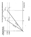
- Figure 4 shows an embodiment of the relationship between the battery voltage Vb and the cranking time t.
- cranking is prohibited if the total count value Cn for the cranking counter C exceeds the threshold value C1, and cranking is permitted if the total count value Cn falls to or below the preset threshold value C2 (for example, 80 in an embodiment).
- the threshold value C1 for the total count value Cn prohibiting cranking, and the threshold value C2 for the total count value Cn permitting cranking are both optimized according to the ratings and performance of the starter motor 10 and the battery power supply distribution equipment/devices.
- the total count value Cn permitting cranking and prohibiting cranking may be optimized for any reasons.
- the difference (C1 - C2) between the threshold value C1 for the total count value Cn prohibiting cranking and the threshold value C2 for the total count value Cn permitting cranking is a count value representing, or corresponding to, a period of time for carrying out auto-cranking when the pushbutton switch 5 is operated.
- This period is referred to hereafter as the "set cranking period" and, in the illustrated embodiment, is a length of time substantially corresponding to a count value of 10 (i.e. 90 - 80) by the counter C.
- the set cranking period (C1 - C2) counted by the total count value Cn for the cranking counter C may be determined only by the relative values of C1 and C2 (i.e. the difference between the values of C1 and C2) and may therefore be independent of the absolute values thereof and substantially constant for all values of Cn.
- the actual cranking time varies in dependence on the difference between the values of C1 and C2 and/or the counting coefficient Cu.
- cranking is performed for the set cranking period, i.e. a count of (C1 - C2). In one embodiment, this cranking requires a momentary operation of the start/stop switch 5. In another embodiment, this cranking occurs automatically without additional operation of the switch. When the total count value Cn once again reaches the threshold value C1, cranking is again prohibited.
- the set cranking period may vary according to the battery voltage Vb. More specifically, the higher the battery voltage Vb, the shorter the set cranking period. This leads to a reduction in the load on the starter motor 10 and the battery power supply distribution equipment/devices.
- the higher the battery voltage Vb the greater the load applied to the starter motor 10 and the battery power supply distribution equipment/devices. This results in a temperature rise. Therefore, when the battery voltage Vb is high, the total cranking time is reduced. This reduces the load on the starter motor 10 and the power supply distribution equipment/devices, thereby suppressing the rise in temperature.
- the load on the starter motor 10 and the battery distribution equipment/devices can be made uniform even if the battery voltage Vb varies. This is accomplished by increasing the count-up coefficient Cu as the battery voltage Vb increases.
- step 12 whether the total current count value Cn for cranking counter C exceeds the threshold value C1 is determined, and when the total count value Cn exceeds the threshold value C1, the process moves to step 18 to stop cranking after the buzzer 16 sounds a warning in step 16.
- the process moves to step 13 and cranking may continue.
- step 13 when the total count value Cn is at or below the threshold value C1, whether or not the set cranking period (C1 - C2) has been exceeded is determined. More specifically, whether or not the total count value Cn for the cranking counter C has counted up the set cranking period (C1 - C2) is determined.
- the process moves to step 17.
- the set cranking period (C1 - C2) has not passed, the process moves to step 14 and cranking may continue. In other words, if the total count value Cn is less than or equal to C1 but the engine has been continuously cranked for a period of time exceeding the set cranking period, the process moves to step 17. Otherwise the process moves to step 14, described below.
- step 17 i.e. when cranking has been carried out for the set cranking period (C1 - C2) but Cn is at or below C1, whether or not the pushbutton switch 5 is still being operated is checked.
- an auto-cranking mode there is an auto-cranking mode and a manual cranking mode.
- the engine In the auto-cranking mode, the engine is allowed to be cranked by the starter motor 10 when the pushbutton switch 5 is operated momentarily (i.e. pressed and released). More specifically, when there is a "one push operation", the auto cranking operation is performed and the engine stops the cranking when the engine has started. Here, if the engine does not start, cranking continues for the number of counts in the set cranking period (C1 - C2) and stops after the set cranking period has been exceeded. The operation described above is repeated if there is another one touch operation of the pushbutton switch 5.
- cranking by the starter motor 10 continues even if the set cranking period (C1 - C2) has passed if the pushbutton switch 5 is pressed continuously. Cranking stops if the pushbutton switch 5 is released. If the engine starts during this process, cranking stops even if the pushbutton switch 5 continues to be pushed.
- step 17 if the pushbutton switch 5 is not being operated (i.e. the device is in the auto-cranking mode) the process moves to step 18, described below.
- step 17 the pushbutton switch 5 continues to be operated (i.e. the device is in manual cranking mode)
- the process moves to step 14 and cranking may continue, even though the set cranking period (C1 - C2) has passed. If operation of the pushbutton switch 5 is discontinued when the set cranking period (C1 - C2) has passed, the process moves to step 18 and cranking is stopped.
- step 14 when the total count value Cn for the cranking counter C is at or below the threshold value C1 and the set cranking period (C1 - C2) has not been exceeded, a determination is made as to whether the engine has been started. This determination is made when the engine speed detected by the speed sensor 14 is at or above a preset threshold speed.
- the threshold speed for the engine speed mentioned above is, for example, set to an engine speed a little lower than idle speed, but higher than the engine speed during cranking. Of course, one skilled in the art will readily recognize that other speeds may be used instead of that disclosed above.
- step 11 If, the engine has not started, the process returns to step 11, and the process is repeated while cranking continues. On the other hand, if the engine has started, the process moves to step 15, and the cranking counter C is cleared. Also, the relay 4 is turned off (open circuit) and battery power to the starter ceases and engine cranking is stopped.
- step 18 when the total count value Cn for the cranking counter C exceeds the threshold value C1 during cranking, or when the pushbutton switch 5 is released when the set cranking period (C1 - C2) has passed, the relay 4 is turned off (open circuit). Also, battery power to the starter motor 10 ceases and engine cranking is stopped.
- step 19 the cranking counter C counts down.
- cranking restart is prohibited until the total count value Cn reaches the threshold value C2 (see, for example, Figure 4 ).
- Cn the total count value for the cranking counter C during the count down during the current cycle of the equation
- tn the count-down time for the current cycle of the equation
- Cn-1 the total count value for the cranking counter C during the count down during the previous cycle of the equation
- tn-1 the count down time during the previous cycle of the equation
- Cd is the down-count coefficient, which is set according to the ratings and performance of the starter motor 10 and the battery power supply distribution equipment/devices. As before, Cd may be set based on other reasons. The smaller the value set for the count-down coefficient, the slower the count down speed and the count down period. More specifically, the cranking restart prohibition period becomes longer with a reduction in the count-down coefficient.
- Cn the down-count coefficient
- step 20 it is determined whether the total count value Cn has counted down to the threshold value C2 or lower. If the total count value Cn reaches the threshold value C2 or lower, the process moves to step 21 and the buzzer 16 alarm is cancelled. Subsequently, the process returns to step 1, and the above-described process is repeated. On the other hand, when the total count value Cn is greater than the threshold value C2, the process returns to step 19, and the count down described above is repeated.
- Figure 5 shows an embodiment of the cranking restart prohibition period when cranking is performed using manual cranking mode.
- cranking is prohibited at time t2 if the total count value Cn exceeds the threshold value C1.
- the cranking counter C counts down with the total count value Cn decreasing along the dashed line (A).
- the slope of this counting is set by the down-count coefficient Cd described above, and the cranking restart prohibition period (t2 - t4) up to the point where the total count value Cn reaches the threshold value C2 (for example, 80) from the threshold value C1 (for example, 90) is (for example, 90 - 80) x Cd [sec].
- cranking counter C counts down and the total count value Cn falls along the dashed line (B).
- the slope during this counting is also set by the down-count coefficient Cd, and the cranking restart prohibition period (t1 - t3) up to the point where the total count value Cn reaches the threshold value C2 (for example, 80) from the total count value Cn of 85 is (85 - 80) x Cd [sec].
- the threshold values C1 and C2 are set according to the ratings and performance of the starter motor 10 and the battery power supply distribution equipment/devices. Along with prohibiting cranking if the total count value Cn calculated by Equation (1) and Equation (2) exceeds the threshold value C1, restart of cranking is permitted if the total count value Cn is at or below the threshold value C2.
- the values C1 and C2 maybe set for any reason, including those discussed above.
- the effective cranking time Tk is timed, with the time when the pushbutton switch 5 is pushed and the first cranking starts to the engine start completion during cranking being timed by a timer. The time while cranking is halted is then subtracted from the added time. Furthermore, cranking is prohibited if the effective cranking time Tk exceeds a preset threshold value T1, and when the effective cranking time Tk is a preset threshold value T2 or lower, cranking restart is permitted. Furthermore, the cranking prohibition threshold value T1 and the cranking restart permitting threshold value T2, for the effective cranking time Tk described above, may be changed according to the battery voltage Vb and the ratings and performance of the starter motor and the battery power supply distribution equipment/devices.
- the effective cranking time Tk may be corrected to be longer as the battery voltage Vb becomes larger, and the cranking prohibition threshold value T1 and the cranking restart permitting threshold value T2, for the effective cranking time Tk, may be changed according to the ratings and performance of the starter motor 10 and the battery power supply distribution equipment/devices.
- the effective cranking time is kept until it is determined that the engine has started. This determination is performed by adding the time during cranking and subtracting time from the added time when cranking is halted. Cranking is prevented if the effective cranking time exceeds a preset cranking prohibition threshold value, and cranking restart is permitted if the effective cranking time reaches a preset cranking restart permitting threshold value or lower.
- loads greater than or equal to the permissible values for ratings and performance of the starter motor and the battery power supply distribution equipment/devices are not applied thereto, and the engine may be efficiently started in a range that does not exceed the ratings and performance of the starter motor and the battery power supply distribution equipment/devices.
- the invention provides an apparatus and/or a method for starting an engine having manual cranking and/or auto-cranking modes.
- cranking of the engine occurs after a start switch 5 is pressed and continues until either the engine starts or until the count value Cn of a counter C reaches or passes a predetermined threshold level C1. If the engine has not started when the count value Cn passes the threshold value C1, cranking is stopped and the counter is reversed. Further cranking is prohibited until the count value Cn reaches or passes a second predetermined threshold level C2.
- cranking of the engine occurs after the start switch 5 is pressed momentarily and continues until either the engine starts or until a set cranking period has expired, as determined by the counter C.
- the set cranking period is deemed to have expired when the count value Cn of the counter C has increased by an amount equal to the difference between the threshold values C1 and C2. If the engine has not started when the set cranking period expires, cranking is halted and the counter is reversed. Thereafter, the count value Cn decreases until such time as the start switch is pressed again. On a subsequent operation of the start switch, if the count value Cn is still less than C1, the engine is once more cranked until the set cranking period has expired again.
- This cycle is repeated until the count value Cn exceeds the threshold value C1. If the engine has not started when the count value Cn passes C1, cranking is stopped and the counter is reversed. Further cranking is prohibited until the count value Cn reaches or passes the second predetermined threshold level C2. Thereafter, if the start switch is pressed again, the cycle is repeated with the engine being cranked for the set cranking period but with cranking always being stopped when the count value Cn passes C1 and being permitted to re-start only when Cn reaches or passes C2.
Landscapes
- Engineering & Computer Science (AREA)
- Chemical & Material Sciences (AREA)
- Combustion & Propulsion (AREA)
- Mechanical Engineering (AREA)
- General Engineering & Computer Science (AREA)
- Combined Controls Of Internal Combustion Engines (AREA)
- Electrical Control Of Air Or Fuel Supplied To Internal-Combustion Engine (AREA)
Claims (11)
- Vorrichtung zum Anlassen oder zum Steuern des Anlassens einer Maschine, Folgendes umfassend:Zählmittel (c) zum Zählen eines Zählwertes (Cn) vom Beginn des Startens der Maschine,Spannungserfassungsmittel zum Erfassen einer Spannung (Vb) einer Batterie (9), die einen Anlassermotor (10) mit Elektroenergie versorgt, um das Starten der Maschine auszuführen,Steuerungsmittel, die ausgebildet sind, um das Starten der Maschine zu unterbinden, wenn der Zählwert (Cn) des Zählers (C) einen ersten Grenzwert (C1) erreicht oder überschreitet,dadurch gekennzeichnet, dass die Steuerungsmittel ausgebildet sind, um die Dauer des Startens bis der erste Grenzwert (C1) erreicht ist zu verkürzen, wenn die Spannung (Vb) der Batterie (9) größer als ein festgelegter Spannungswert ist.
- Vorrichtung gemäß Anspruch 1, wobei die Steuerungsmittel ausgebildet sind, um das Starten der Maschine über einen ersten festgelegten Zeitraum zu unterbinden, nachdem der Zählwert (Cn) den ersten Grenzwert (C1) erreicht oder überschritten hat.
- Vorrichtung gemäß Anspruch 1 oder 2, wobei die Zählmittel (C) ausgebildet sind, um den Zählwert (Cn) zurückzuzählen, wenn das Starten der Maschine unterbunden wird, und die Steuerungsmittel ausgebildet sind, um das Starten der Maschine zuzulassen, wenn der Zählwert (Cn) einen zweiten Grenzwert (C2) erreicht oder unterchreitet.
- Vorrichtung gemäß Anspruch 3, wobei der erste und der zweite Grenzwert (C1, C2) auf Basis eines Bemessungswertes oder von Leistungsmerkmalen eines Anlassermotors (10) zum Ausführen des Startens der Maschine bestimmt sind.
- Vorrichtung gemäß einem der vorhergehenden Ansprüche, wobei die Steuerungsmittel ausgebildet sind, um das Starten der Maschine in Abhängigkeit von dem ersten und dem zweiten festgelegten Wert (C1, C2) nach einem zweiten festgelegten Zeitraum zu stoppen, der dem Beginn des Startens einer Maschine folgt.
- Vorrichtung gemäß Anspruch 5, wobei der erste und/oder der zweite festgelegte Zeitraum im Wesentlichen einem Zählwert zwischen dem ersten und dem zweiten Grenzwert (C1, C2) entspricht.
- Vorrichtung gemäß einem der vorhergehenden Ansprüche, wobei die Steuerungsmittel ausgebildet sind, um:eine Zeit aus einem vorhergehenden Zyklus zu erhalten,eine gegenwärtige Zeit zu erhalten,die Zeit des vorhergehenden Zyklus von der gegenwärtigen Zeit zu subtrahieren, um eine Änderung der Zeit bereitzustellen,die Änderung der Zeit mit einem Koeffizienten (Cu) zu multiplizieren, um einen Zähleränderungswert zu erhalten, undden Zähleränderungswert zu einem vorhergehenden Zählwert (Cn-1) für den vorhergehenden Zyklus hinzu zu addieren, um den Zählwert (Cn) zu erzeugen.
- Vorrichtung gemäß Anspruch 7, wobei die Steuerungsmittel ausgebildet sind, um als Reaktion darauf, dass die Spannung (Vb) der Batterie (9) größer als der festgelegte Spannungswert ist, den Umfang oder die Dauer des Startens zu verringern, indem der Wert des Koeffizienten (Cu) erhöht wird.
- Vorrichtung gemäß einem der vorhergehenden Ansprüche, ferner umfassend Anlassbestimmungsmittel, um zu bestimmen, ob die Maschine angelassen wurde, und um das Starten der Maschine zu unterbinden, nachdem die Maschine angelassen wurde.
- Fahrzeug mit einer Vorrichtung gemäß einem der vorhergehenden Ansprüche.
- Verfahren zum Anlassen oder zum Steuern des Anlassens einer Maschine, folgende Schritte umfassend:das Zählen eines Zählwertes vom Beginn des Startens der Maschine,das Erfassen einer Spannung (Vb) einer Batterie (9), die einen Anlassermotor (10) mit Elektroenergie versorgt, um das Starten der Maschine auszuführen, unddas Unterbinden weiteren Startens der Maschine über einen ersten festgelegten Zeitraum, wenn der Zählwert einen ersten Grenzwert (C1) erreicht oder überschreitet,gekennzeichnet durch das Verkürzen der Dauer des Startens bis der erste Grenzwert (C1) erreicht ist, wenn die Spannung (Vb) der Batterie (9) größer als ein festgelegter Spannungswert ist.
Applications Claiming Priority (2)
| Application Number | Priority Date | Filing Date | Title |
|---|---|---|---|
| JP2004091750 | 2004-03-26 | ||
| JP2004091750A JP4092503B2 (ja) | 2004-03-26 | 2004-03-26 | エンジン始動装置およびエンジン始動方法 |
Publications (3)
| Publication Number | Publication Date |
|---|---|
| EP1580424A2 EP1580424A2 (de) | 2005-09-28 |
| EP1580424A3 EP1580424A3 (de) | 2007-05-23 |
| EP1580424B1 true EP1580424B1 (de) | 2010-11-03 |
Family
ID=34858493
Family Applications (1)
| Application Number | Title | Priority Date | Filing Date |
|---|---|---|---|
| EP05251899A Expired - Lifetime EP1580424B1 (de) | 2004-03-26 | 2005-03-29 | Verfahren und Vorrichtung zum Anlassen einer Brennkraftmaschine |
Country Status (4)
| Country | Link |
|---|---|
| US (1) | US7216616B2 (de) |
| EP (1) | EP1580424B1 (de) |
| JP (1) | JP4092503B2 (de) |
| DE (1) | DE602005024472D1 (de) |
Families Citing this family (33)
| Publication number | Priority date | Publication date | Assignee | Title |
|---|---|---|---|---|
| JP2006070752A (ja) * | 2004-08-31 | 2006-03-16 | Nissan Motor Co Ltd | エンジン始動制御装置および制御方法 |
| JP4250149B2 (ja) * | 2005-05-10 | 2009-04-08 | 株式会社デンソー | エンジン始動制御システム |
| US7948099B2 (en) * | 2005-05-26 | 2011-05-24 | Renault Trucks | Method of controlling power supply to an electric starter |
| KR101189221B1 (ko) | 2006-03-15 | 2012-10-09 | 현대자동차주식회사 | 자동 변속기 차량의 시동 제어장치 |
| WO2008029363A2 (en) * | 2006-09-05 | 2008-03-13 | Ford Otomotiv Sanayi Anonim Sirketi | A method for protection of a starter |
| US20080109150A1 (en) * | 2006-11-07 | 2008-05-08 | Pfohl Jesse L | Starter inter-lock for an internal combustion engine |
| JP4712735B2 (ja) * | 2007-01-29 | 2011-06-29 | 古河電気工業株式会社 | 車両用昇圧装置 |
| JP2008263309A (ja) * | 2007-04-10 | 2008-10-30 | Sony Corp | 電子機器、リモートコントローラおよび遠隔操作システム |
| US7806095B2 (en) * | 2007-08-31 | 2010-10-05 | Vanner, Inc. | Vehicle starting assist system |
| JP4840667B2 (ja) * | 2007-09-25 | 2011-12-21 | スズキ株式会社 | プッシュスタート制御装置 |
| KR100896904B1 (ko) | 2007-11-13 | 2009-05-12 | 현대자동차주식회사 | 크랭킹 상태에서 버튼시동시스템의 전원이동 방법 |
| JP4907573B2 (ja) * | 2008-03-12 | 2012-03-28 | 富士重工業株式会社 | エンジンの始動制御装置 |
| US8319472B2 (en) * | 2009-01-19 | 2012-11-27 | GM Global Technology Operations LLC | Method and system for internally jump-starting an engine |
| JP4743669B2 (ja) * | 2009-03-16 | 2011-08-10 | トヨタ自動車株式会社 | 電子キー |
| FR2944326B1 (fr) * | 2009-04-10 | 2015-10-16 | Valeo Equip Electr Moteur | Procede de protection thermique d'un systeme d'arret/relance automatique de moteur thermique et systeme l'utilisant |
| US8261872B2 (en) * | 2009-06-08 | 2012-09-11 | Clark Equipment Company | Work machine having modular ignition switch keypad with latching output |
| JP2011017271A (ja) * | 2009-07-08 | 2011-01-27 | Yanmar Co Ltd | 作業車両のエンジン制御装置 |
| CN102695867B (zh) * | 2009-11-10 | 2015-08-05 | 三菱自动车工业株式会社 | 车辆启动控制装置 |
| US8171907B2 (en) * | 2009-11-19 | 2012-05-08 | Briggs And Stratton Corporation | Push button starting system for outdoor power equipment |
| US9624890B2 (en) | 2009-11-19 | 2017-04-18 | Briggs & Stratton Corporation | Push button starting system module for outdoor power equipment |
| DE102010030830A1 (de) | 2010-07-01 | 2012-01-05 | Robert Bosch Gmbh | Verfahren zum Betreiben einer Temperaturbegrenzungseinrichtung, Temperaturbegrenzungseinrichtung sowie elektrisches Gerät |
| WO2012125963A2 (en) | 2011-03-16 | 2012-09-20 | Johnson Controls Technology Company | Energy source devices and systems having a battery and an ultracapacitor |
| JP5964726B2 (ja) * | 2012-11-02 | 2016-08-03 | 株式会社東海理化電機製作所 | 電子キー登録システム |
| US9925933B2 (en) | 2013-08-30 | 2018-03-27 | Ford Global Technologies, Llc | Pre-charge quick key cycling protection |
| CN104554091B (zh) * | 2013-10-25 | 2018-10-09 | 标致雪铁龙(中国)汽车贸易有限公司 | 用于车辆的控制系统 |
| CN114233549B (zh) * | 2015-06-29 | 2024-01-02 | 康明斯有限公司 | 管理自动停止/启动频率 |
| US10337438B2 (en) * | 2015-10-01 | 2019-07-02 | GM Global Technology Operations LLC | Push-button start system fault diagnosis |
| US10448628B2 (en) * | 2017-03-27 | 2019-10-22 | Cnh Industrial America Llc | Electronic start system for an agricultural machine |
| US10480478B2 (en) | 2018-04-23 | 2019-11-19 | Fca Us Llc | Diagnostic techniques for a clutch interlock switch and a clutch pedal position sensor |
| AU2019468354A1 (en) | 2019-10-02 | 2022-04-21 | Honda Motor Co., Ltd. | Starting system for internal combustion engine and lawnmower including same |
| EP4095373B1 (de) * | 2020-01-21 | 2025-02-26 | NISSAN MOTOR Co., Ltd. | Verfahren und vorrichtung zur nicht-leerlaufregelung eines fahrzeuges |
| US11869737B2 (en) | 2021-12-08 | 2024-01-09 | Ford Global Technologies, Llc | Push-button switch assembly and diagnosic methods thereof |
| CN114483412A (zh) * | 2022-01-29 | 2022-05-13 | 江门市大长江集团有限公司 | 发动机启动控制方法、设备、装置、摩托车和存储介质 |
Family Cites Families (6)
| Publication number | Priority date | Publication date | Assignee | Title |
|---|---|---|---|---|
| US4653442A (en) * | 1985-10-15 | 1987-03-31 | Onan Corporation | Engine starting cycle and overcrank control system |
| US4901690A (en) * | 1988-12-12 | 1990-02-20 | General Motors Corporation | Electronic starting motor system having timed cranking period control |
| FR2688548A1 (fr) * | 1992-03-13 | 1993-09-17 | Duranton Andre | Dispositif d'assistance au demarrage d'un moteur a combustion interne. |
| US5601058A (en) * | 1995-03-06 | 1997-02-11 | The United States Of America As Represented By The Department Of Energy | Starting apparatus for internal combustion engines |
| FR2756873B1 (fr) * | 1996-12-11 | 1999-02-26 | Valeo Equip Electr Moteur | Perfectionnements aux procedes et dispositifs pour la commande d'un demarreur de vehicule automobile |
| JP4334117B2 (ja) * | 2000-07-19 | 2009-09-30 | 本田技研工業株式会社 | 原動機用セルフスタータモータ制御装置 |
-
2004
- 2004-03-26 JP JP2004091750A patent/JP4092503B2/ja not_active Expired - Lifetime
-
2005
- 2005-03-28 US US11/091,119 patent/US7216616B2/en not_active Expired - Lifetime
- 2005-03-29 EP EP05251899A patent/EP1580424B1/de not_active Expired - Lifetime
- 2005-03-29 DE DE602005024472T patent/DE602005024472D1/de not_active Expired - Lifetime
Also Published As
| Publication number | Publication date |
|---|---|
| JP4092503B2 (ja) | 2008-05-28 |
| US7216616B2 (en) | 2007-05-15 |
| US20050247280A1 (en) | 2005-11-10 |
| JP2005273615A (ja) | 2005-10-06 |
| EP1580424A3 (de) | 2007-05-23 |
| EP1580424A2 (de) | 2005-09-28 |
| DE602005024472D1 (de) | 2010-12-16 |
Similar Documents
| Publication | Publication Date | Title |
|---|---|---|
| EP1580424B1 (de) | Verfahren und Vorrichtung zum Anlassen einer Brennkraftmaschine | |
| JP4144348B2 (ja) | エンジン始動システム | |
| US6526931B1 (en) | Method and systems for the automatic control of the cutting off and restarting of the thermal engine of a vehicle during temporary immobilizations thereof | |
| EP1416142B1 (de) | Motorsteuerung für ein Fahrzeug mit elektronischem Schlüssel | |
| US20070267238A1 (en) | Method of Inhibiting the Automatic Stop Control System of the Heat Engine of a Vehicle in the Absence of a Driver | |
| US8616169B2 (en) | Method of inhibiting the automatic stop control system of the heat engine of a vehicle in congested traffic | |
| US20120130604A1 (en) | Automatic shutdown system for automobiles | |
| EP1717116B1 (de) | Steuervorrichtung, Steuerverfahren und Computerprogramm für ein Fahrzeug | |
| US7143732B2 (en) | Idling stop control apparatus | |
| JP2008513680A (ja) | 回転電気機器を制御する方法および装置 | |
| JP5853986B2 (ja) | アイドルストップ制御装置 | |
| CA2449063C (en) | Engine start controller, engine start control method, and recording medium having program recorded therein for performing the method | |
| WO2006099520A2 (en) | Remote control of engine operation in a motor vehicle | |
| KR102147111B1 (ko) | 차량 또는 산업용 엔진의 배터리 충전을 위한 자동 시동 장치 | |
| US7481194B2 (en) | Method of limiting the number of times a vehicle heat engine can automatically stop and start | |
| JP4222182B2 (ja) | 車両の制御装置 | |
| CN102022199B (zh) | 用于控制内燃机的运行的装置和方法 | |
| WO1998014702A1 (en) | A system for the automatic cut off of a car's engine and its automatic restart | |
| JP4694396B2 (ja) | エンジンの始動制御装置 | |
| CA2712524A1 (en) | Vehicle shutoff systems | |
| EP2006519B1 (de) | Steuerung für ein Fahrzeug | |
| JP4274015B2 (ja) | 車両の電源装置 | |
| JP2005264860A (ja) | 車両の電源装置 | |
| KR20210053170A (ko) | 차량 또는 산업용 엔진의 배터리 충전을 위한 자동 시동 장치 | |
| JP4165032B2 (ja) | エンジン始動制御装置 |
Legal Events
| Date | Code | Title | Description |
|---|---|---|---|
| PUAI | Public reference made under article 153(3) epc to a published international application that has entered the european phase |
Free format text: ORIGINAL CODE: 0009012 |
|
| AK | Designated contracting states |
Kind code of ref document: A2 Designated state(s): AT BE BG CH CY CZ DE DK EE ES FI FR GB GR HU IE IS IT LI LT LU MC NL PL PT RO SE SI SK TR |
|
| AX | Request for extension of the european patent |
Extension state: AL BA HR LV MK YU |
|
| PUAL | Search report despatched |
Free format text: ORIGINAL CODE: 0009013 |
|
| AK | Designated contracting states |
Kind code of ref document: A3 Designated state(s): AT BE BG CH CY CZ DE DK EE ES FI FR GB GR HU IE IS IT LI LT LU MC NL PL PT RO SE SI SK TR |
|
| AX | Request for extension of the european patent |
Extension state: AL BA HR LV MK YU |
|
| 17P | Request for examination filed |
Effective date: 20071123 |
|
| AKX | Designation fees paid |
Designated state(s): DE FR GB |
|
| 17Q | First examination report despatched |
Effective date: 20081210 |
|
| GRAP | Despatch of communication of intention to grant a patent |
Free format text: ORIGINAL CODE: EPIDOSNIGR1 |
|
| GRAS | Grant fee paid |
Free format text: ORIGINAL CODE: EPIDOSNIGR3 |
|
| GRAA | (expected) grant |
Free format text: ORIGINAL CODE: 0009210 |
|
| AK | Designated contracting states |
Kind code of ref document: B1 Designated state(s): DE FR GB |
|
| REG | Reference to a national code |
Ref country code: GB Ref legal event code: FG4D |
|
| REF | Corresponds to: |
Ref document number: 602005024472 Country of ref document: DE Date of ref document: 20101216 Kind code of ref document: P |
|
| PLBE | No opposition filed within time limit |
Free format text: ORIGINAL CODE: 0009261 |
|
| STAA | Information on the status of an ep patent application or granted ep patent |
Free format text: STATUS: NO OPPOSITION FILED WITHIN TIME LIMIT |
|
| 26N | No opposition filed |
Effective date: 20110804 |
|
| REG | Reference to a national code |
Ref country code: DE Ref legal event code: R097 Ref document number: 602005024472 Country of ref document: DE Effective date: 20110804 |
|
| REG | Reference to a national code |
Ref country code: FR Ref legal event code: PLFP Year of fee payment: 12 |
|
| REG | Reference to a national code |
Ref country code: FR Ref legal event code: PLFP Year of fee payment: 13 |
|
| REG | Reference to a national code |
Ref country code: FR Ref legal event code: PLFP Year of fee payment: 14 |
|
| REG | Reference to a national code |
Ref country code: DE Ref legal event code: R084 Ref document number: 602005024472 Country of ref document: DE |
|
| REG | Reference to a national code |
Ref country code: GB Ref legal event code: 746 Effective date: 20230929 |
|
| PGFP | Annual fee paid to national office [announced via postgrant information from national office to epo] |
Ref country code: DE Payment date: 20240220 Year of fee payment: 20 Ref country code: GB Payment date: 20240221 Year of fee payment: 20 |
|
| PGFP | Annual fee paid to national office [announced via postgrant information from national office to epo] |
Ref country code: FR Payment date: 20240220 Year of fee payment: 20 |
|
| REG | Reference to a national code |
Ref country code: DE Ref legal event code: R071 Ref document number: 602005024472 Country of ref document: DE |
|
| REG | Reference to a national code |
Ref country code: GB Ref legal event code: PE20 Expiry date: 20250328 |
|
| PG25 | Lapsed in a contracting state [announced via postgrant information from national office to epo] |
Ref country code: GB Free format text: LAPSE BECAUSE OF EXPIRATION OF PROTECTION Effective date: 20250328 |