EP1580153B1 - Dispositif et procédé pour transférer des articles en feuille - Google Patents
Dispositif et procédé pour transférer des articles en feuille Download PDFInfo
- Publication number
- EP1580153B1 EP1580153B1 EP05290539A EP05290539A EP1580153B1 EP 1580153 B1 EP1580153 B1 EP 1580153B1 EP 05290539 A EP05290539 A EP 05290539A EP 05290539 A EP05290539 A EP 05290539A EP 1580153 B1 EP1580153 B1 EP 1580153B1
- Authority
- EP
- European Patent Office
- Prior art keywords
- group
- article
- row
- projecting
- articles
- Prior art date
- Legal status (The legal status is an assumption and is not a legal conclusion. Google has not performed a legal analysis and makes no representation as to the accuracy of the status listed.)
- Expired - Lifetime
Links
Images



Classifications
-
- B—PERFORMING OPERATIONS; TRANSPORTING
- B65—CONVEYING; PACKING; STORING; HANDLING THIN OR FILAMENTARY MATERIAL
- B65H—HANDLING THIN OR FILAMENTARY MATERIAL, e.g. SHEETS, WEBS, CABLES
- B65H3/00—Separating articles from piles
- B65H3/24—Separating articles from piles by pushers engaging the edges of the articles
- B65H3/242—Separating articles from piles by pushers engaging the edges of the articles for separating a part of the pile, i.e. several articles at once
- B65H3/245—Separating articles from piles by pushers engaging the edges of the articles for separating a part of the pile, i.e. several articles at once the pile being pre-marked
-
- B—PERFORMING OPERATIONS; TRANSPORTING
- B65—CONVEYING; PACKING; STORING; HANDLING THIN OR FILAMENTARY MATERIAL
- B65H—HANDLING THIN OR FILAMENTARY MATERIAL, e.g. SHEETS, WEBS, CABLES
- B65H3/00—Separating articles from piles
- B65H3/46—Supplementary devices or measures to assist separation or prevent double feed
- B65H3/54—Pressing or holding devices
-
- B—PERFORMING OPERATIONS; TRANSPORTING
- B65—CONVEYING; PACKING; STORING; HANDLING THIN OR FILAMENTARY MATERIAL
- B65H—HANDLING THIN OR FILAMENTARY MATERIAL, e.g. SHEETS, WEBS, CABLES
- B65H31/00—Pile receivers
- B65H31/30—Arrangements for removing completed piles
- B65H31/3081—Arrangements for removing completed piles by acting on edge of the pile for moving it along a surface, e.g. by pushing
-
- B—PERFORMING OPERATIONS; TRANSPORTING
- B65—CONVEYING; PACKING; STORING; HANDLING THIN OR FILAMENTARY MATERIAL
- B65H—HANDLING THIN OR FILAMENTARY MATERIAL, e.g. SHEETS, WEBS, CABLES
- B65H33/00—Forming counted batches in delivery pile or stream of articles
- B65H33/06—Forming counted batches in delivery pile or stream of articles by displacing articles to define batches
- B65H33/10—Displacing the end articles of a batch
-
- B—PERFORMING OPERATIONS; TRANSPORTING
- B65—CONVEYING; PACKING; STORING; HANDLING THIN OR FILAMENTARY MATERIAL
- B65H—HANDLING THIN OR FILAMENTARY MATERIAL, e.g. SHEETS, WEBS, CABLES
- B65H2301/00—Handling processes for sheets or webs
- B65H2301/40—Type of handling process
- B65H2301/42—Piling, depiling, handling piles
- B65H2301/422—Handling piles, sets or stacks of articles
- B65H2301/4226—Delivering, advancing piles
- B65H2301/42266—Delivering, advancing piles by acting on edge of the pile for moving it along a surface, e.g. pushing
-
- B—PERFORMING OPERATIONS; TRANSPORTING
- B65—CONVEYING; PACKING; STORING; HANDLING THIN OR FILAMENTARY MATERIAL
- B65H—HANDLING THIN OR FILAMENTARY MATERIAL, e.g. SHEETS, WEBS, CABLES
- B65H2701/00—Handled material; Storage means
- B65H2701/10—Handled articles or webs
- B65H2701/18—Form of handled article or web
- B65H2701/182—Piled package
- B65H2701/1826—Arrangement of sheets
- B65H2701/18265—Ordered set of batches of articles
- B65H2701/18267—Ordered set of batches of articles wherein the batches are separated by separator elements in the pile
-
- B—PERFORMING OPERATIONS; TRANSPORTING
- B65—CONVEYING; PACKING; STORING; HANDLING THIN OR FILAMENTARY MATERIAL
- B65H—HANDLING THIN OR FILAMENTARY MATERIAL, e.g. SHEETS, WEBS, CABLES
- B65H2701/00—Handled material; Storage means
- B65H2701/10—Handled articles or webs
- B65H2701/19—Specific article or web
- B65H2701/1916—Envelopes and articles of mail
Definitions
- the present invention relates to sheet article transfer devices.
- the present invention relates to a device for transferring groups of sheet articles from a first to a second area, these items being arranged in the first area in a row, with certain items in the row protruding on the same area. side of the latter, so that groups of articles are delimited between the outgoing articles.
- Such a device is for example located between two stations of a production line of sheet articles, for example a manufacturing station and a packaging station.
- the known devices are generally semi-automatic, that is to say that they require an operator to form sub-packets of articles from packets delivered by a machine on the first area. In addition, the operators must transfer the packets themselves to the transfer station.
- the transfer phase is not carried out quickly and limits the output of the production line.
- the document is also known WO 95/32139 which describes a device for separating a group of articles from a row of articles.
- This device comprises means for gripping an overlying article which forms a limit for that group to be transferred, means for moving said overlying article apart so as to isolate said group from the row and means for transferring said isolated group into the second area.
- the protruding article is grasped here by means of a clamp formed of two articulated arms.
- Gripping has the disadvantage of not presenting the speed and precision necessary for the transfer of articles at a high rate.
- the present invention proposes to remedy these disadvantages.
- the means for grasping an outgoing article comprises at least one suction head adapted to create a suction force to press against it an area of the article protruding.
- the articles are arranged vertically in the row, against each other.
- the articles of the row are substantially inclined relative to the vertical, for example in the case where the articles have on one of their faces an extra thickness causing a deformation of the row.
- the first and second areas respectively correspond to the output of a sheet-article-making machine and to the input of a sheet-article-group-packaging device.
- the isolation of a group of the row is done in two stages: firstly the seizure of an outgoing article makes it possible to select the group to be transferred, then the distance from the The protruding article makes it possible to isolate the group to be transferred from the other articles in the row.
- the spacing of the protruding article consists in particular of establishing between this article and an adjacent article a space which has a non-zero dimension in the longitudinal direction of the row.
- Isolating the group of items from the rest of the row before transferring it to the second area has the advantage of ensuring that the transfer means will move exactly the desired number of items.
- An advantage of providing at least one suction head lies in the speed of the control thereof, which allows to enter or release very quickly an outgoing item.
- suction head Another advantage of using a suction head is that one can grasp or release an article protruding without having to move the input means.
- the transfer system is adapted to transfer in the second area an end group of the row which is delimited between the first article of said row and said discarded article, considered from a free end of the row.
- the device comprises a stop to keep the group to be transferred to an end of said group opposite to the projecting article.
- the stop comprises two separate plates, but it can also be formed in one piece.
- the device comprises two suction heads spaced to grasp the article protruding into two distinct zones.
- the suction heads are placed on the same side with respect to the edge protruding from an overhanging article, but they can however be placed on either side of an overhanging article.
- the pneumatic circuits which feed the suction heads are independent.
- the heads can also be connected together to the same pneumatic circuit.
- said at least one suction head is adjustable in position in the direction of the length of the row to adapt to the thickness of a group.
- the suction heads can be mounted on the stop so as to be movable in translation in the direction of the length of the row.
- the means for transferring the isolated group comprise at least one pusher capable of pushing the isolated group out of the row.
- the device comprises a single pusher, however, it is also conceivable to use several pushers operating alternately.
- the pusher is movable in translation.
- the direction of the translation is orthogonal to the direction of advancement of the row of articles.
- the means for separating the article protruding are capable of separating said article from the group which it delimits.
- the means for spacing the protruding article are integral with the pusher.
- An interest is to be able to spread the article during the entire phase of movement of the pusher.
- Another advantage is to associate several functions to the pusher, which simplifies the mechanical structure of the device.
- the pusher carries a spacer finger.
- the outgoing article which forms a limit of the group to be transferred is not transferred with the latter, the device comprises repositioning means, to replace said article in the row for the transfer of the next group comprising this article.
- An interest is to be able to transfer all items in the row, including outgoing items.
- the outgoing articles temporarily allow the delimitation of a group. Once a group has been transferred, the protruding articles are preferably repositioned in the row, then transferred to the next group.
- the repositioning means move with the pusher.
- the repositioning means are fixed integrally to the pusher and may be in the form of a projection located on one side of the pusher.
- the repositioning means can be actuated by displacement means independent of those of the pusher.
- the invention also relates to a method for transferring groups of sheet articles from a first to a second area, wherein, for the purpose of transfer, the articles are arranged in the first area in a row by shifting certain items for they project on the same side of the row so that groups of articles are delimited between the protruding articles.
- the method according to the invention proposes to remedy these disadvantages.
- the row has two ends: a first end located at the output of the machine to manufacture the articles and an opposite second end, called the free end.
- the last group of the free end of the row is transferred, that is to say the group delimited between the article at the free end of the row and the first article protruding, considered from the free end of the row.
- the article that exceeds in two distinct areas of this article is entered.
- the distinct areas are the corners of the protruding portion of an overhanging article.
- the isolated group is transferred by pushing it out of the row.
- the isolated group when pushing the isolated group, it slides on the surface of a frame to the second area.
- the group is transferred without the exceeding article which forms a limit for this group and this item is placed in the row.
- the outgoing article will be transferred with the next group.
- one grasps an article protruding one discards this article while allowing a displacement of the group, one transfers the group and one places the article exceeding in the row.
- the protruding article is released before replacing it in the row.
- the group is allowed to move in a direction orthogonal to the direction of advancement of the row of articles.
- the sheet article transfer device and the method for transferring articles according to the invention will be described.
- the particular case in which the sheet articles are mail envelopes will be considered, but the same device and method may be used to transfer sheets of paper or other sheet material.
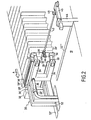
- the installation 10 implementing the method that is the subject of the invention is part of an envelope manufacturing line (not shown here), and more specifically, the installation is located downstream of a machine 14 to manufacture envelopes and upstream of a group of envelopes conditioning station.
- the purpose of the device is to transfer to the conditioning station (not shown here) groups of envelopes produced by the machine 14.
- Envelopes 12 from the machine 14 are brought (by means not shown here) to a first area 16 of the installation being arranged vertically against each other.
- the succession of envelopes 12 forms a row 18 of vertical envelopes which advances on the horizontal surface of a frame 19 in the direction A as and when the following envelopes are brought.
- Means located in the machine and not shown here periodically offset certain envelopes so that they protrude on the same side of the row 18.
- the length of protrusion is preferably substantially the same for each protruding envelope 20, 20 ', 20 ", 20"' ...
- the groups of envelopes contain the same number of envelopes, for example groups of 20, 25, 50, 60, 100, or 120 envelopes can be made.
- the free end 24 of the row 18 is held by a stop formed of two rectangular plates 26, 26 'located substantially in the same plane and whose faces are oriented parallel to the faces of the envelopes.
- the two plates are spaced apart from each other in the direction orthogonal to the surface of the frame 19, so that the lower plate 26 can be distinguished from the upper plate 26 '.
- the interest of the spacing between the two plates will be detailed below.
- the two plates 26, 26 ' are fixed to two support arms 28, 28' integral with a rod 28 "which is movable in translation in a direction parallel to that of the displacement of the row.
- the device also comprises a transfer system 30 which comprises means 32, 32 'for grasping a protruding envelope 20. These means are in the form of two suction heads 32, 32' each mounted on a horizontal arm 34 (resp. 34 ').
- These arms are spaced from each other and positioned one above the other so that one can define a lower arm 34 and an upper arm 34 '.
- the second end of a suction head has a flat face 38, 38 'oriented parallel to the faces of the envelopes and provided with one or more orifices 40, 40 ' connected to the pneumatic suction circuit 36 .
- the suction heads are mounted at the ends of the arms 34, 34 ' for example on adjustable rods 35, 35' so as to be able to adjust the distance between an arm and a face of a suction head.
- the interest is to be able to adapt the device to the thickness of the groups of envelopes.
- the two arms 34, 34 ' are fixed to a jack (not shown here) which allows the displacement in translation in the direction of advance of the row, in both directions. It is in a remote position that will be transferred to the conditioning station, as will be seen later.
- suction heads 32, 32 ' and the plates 26, 26' can move in the same direction.
- the lower arm 34 is integral with the lower plate 26 and the upper arm 34 ' is secured to the upper plate 26' .
- the lower arm 34 and the upper arm 34 ' protrude from the ends of the plates 26, 26' so that, in a secured configuration, the suction heads 32, 32 ' extend perpendicularly with respect to the surface of the plates 26, 26 ' and are arranged vis-à-vis the area that protrudes beyond protruding envelopes.
- the device further comprises a pusher 42 which is in the form of an elongate rod extending horizontally in the direction orthogonal to the direction of advancement of the row.
- the first end of the pusher 42 is fixed to an arm 44 in a mobile manner, so that the position of the pusher can be adjusted in a horizontal plane and in a direction parallel to the direction of travel.
- the arm 44 is also movable (by means not shown here) in translation in the direction orthogonal to the direction advancement of the row.
- these means are jacks located under the frame 19.
- the second end of the pusher 42 comprises an abutment 46 forming a bend with the pusher 42 extending in the direction and the direction of advancement of the row as can be seen in the Figures 1 to 3 .
- the length of the abutment 46 may be adjustable to suit the thickness of the groups of envelopes.
- the second end of the pusher further comprises a finger 48 in the form of an elongated and tapered plate which extends in the direction of the rod 42 protruding therefrom.
- the finger 48 and the abutment 46 form a substantially straight angle whose junction is situated at the end of the pusher 42.
- the pusher includes a projection 49 preferably located on its lateral side and near its second end.
- the pusher can be in two extreme positions: the retracted position represented on the figure 2 and the advanced position represented on the figure 4 .
- the finger 48 In the retracted position, the finger 48 is in a waiting position such that the end of the finger is almost in contact with the lateral side of the row 18 from which protruding envelopes 20, 20 ', 20 ".
- the finger 48 In the advanced position, the finger 48 has passed through the row 18 and is located in the second area between two guide plates 50, 50 ' arranged vertically facing each other and extending in the direction of movement of the rod 42. These guide plates delimit the entrance of the conditioning station.
- the cylinders are preferably located under the frame 19 which is provided with slots 52, 52 ' and 52 " to allow the displacement of the plates 26, 26', arms 34 , 34 'respectively. and arm 44.
- the transfer method firstly comprises a start-up phase represented on the figure 1 .
- the machine is started to manufacture the envelopes 12 and the row 18 begins to form with the protruding envelopes 20, 20 ', 20 ", 20"' (the periodic shifting process of the envelopes is implemented in the machine and is not described here).
- the plates 26, 26 ' are brought into contact with the first envelope exiting the machine so as to keep the envelopes 12 forming the row vertical.
- the plates 26, 26 ' accompany the advancement of the row in the direction A to the transfer system 30, until it is fixed to the magnetized arms 34,34'.
- This step is the end of the start-up phase.
- suction heads 32, 32 ' are actuated so that the protruding area of the protruding envelope 20 is pressed against the face 38, 38' of the suction heads.
- the assembly constituted by the plates 26,26 ' and the suction heads 32,32' backs up so that the central part of the protruding envelope 20 comes into contact with the finger 48 (which is in the position of expectation) as can be seen on the figure 2 .
- the finger 48 retains the central portion of the protruding envelope 20 during the retreat of the assembly formed by the plates 26, 26 ' and the arms 32, 32' which causes in its receding the corners of the envelope 20. The latter is therefore deformed in its central part which is then slightly removed from the group to be transferred.
- the pusher 42 is moved from its retracted position to its advanced position so that the stop 46 pushes the group of envelopes 56 out of the row.
- the finger 48 moves between the last envelope of the group and the protruding envelope spread during the displacement of the group to be transferred.
- protruding envelope 20 remains pressed against the suction heads while the group is pushed out of the row.
- the suction is maintained during this repositioning, however one can also stop the suction by connecting the pneumatic circuits to the open air.
- the group 56 When in the forward position, shown on the figure 5 , the group 56 is transferred into the second area, the protruding envelope 20 is repositioned in the row and simultaneously, the assembly formed by the heads 32, 32 ' and the plates 26, 26' is advanced so as to grip the next overlying envelope 20 ' which forms a limit for the next group to be transferred. This is possible because the pusher 42 can move in the space between the plates 26, 26 '.
- the pusher 42 will be moved at the moment when a new group of envelopes will be taken out of the machine and brought into the row. More precisely, the displacement will take place when a new protruding envelope will be detected at the output of the machine.
Landscapes
- Engineering & Computer Science (AREA)
- Mechanical Engineering (AREA)
- Sheets, Magazines, And Separation Thereof (AREA)
- Feeding Of Articles By Means Other Than Belts Or Rollers (AREA)
- Making Paper Articles (AREA)
- Supplying Of Containers To The Packaging Station (AREA)
- Paper (AREA)
- Packaging For Recording Disks (AREA)
Priority Applications (1)
| Application Number | Priority Date | Filing Date | Title |
|---|---|---|---|
| PL05290539T PL1580153T3 (pl) | 2004-03-26 | 2005-03-10 | Urządzenie i sposób przemieszczania wyrobów z arkusza |
Applications Claiming Priority (2)
| Application Number | Priority Date | Filing Date | Title |
|---|---|---|---|
| FR0403127 | 2004-03-26 | ||
| FR0403127A FR2868059B1 (fr) | 2004-03-26 | 2004-03-26 | Dispositif et procede pour transferer des articles en feuille |
Publications (2)
| Publication Number | Publication Date |
|---|---|
| EP1580153A1 EP1580153A1 (fr) | 2005-09-28 |
| EP1580153B1 true EP1580153B1 (fr) | 2008-03-12 |
Family
ID=34855165
Family Applications (1)
| Application Number | Title | Priority Date | Filing Date |
|---|---|---|---|
| EP05290539A Expired - Lifetime EP1580153B1 (fr) | 2004-03-26 | 2005-03-10 | Dispositif et procédé pour transférer des articles en feuille |
Country Status (6)
| Country | Link |
|---|---|
| EP (1) | EP1580153B1 (pl) |
| AT (1) | ATE388915T1 (pl) |
| DE (1) | DE602005005235T2 (pl) |
| ES (1) | ES2303202T3 (pl) |
| FR (1) | FR2868059B1 (pl) |
| PL (1) | PL1580153T3 (pl) |
Families Citing this family (2)
| Publication number | Priority date | Publication date | Assignee | Title |
|---|---|---|---|---|
| CN110642063B (zh) * | 2018-06-27 | 2021-04-09 | 海德堡印刷机械股份公司 | 用于安放已印刷的且潮湿的页张并且形成页张叠堆的方法 |
| CN110039926B (zh) * | 2019-05-15 | 2020-09-01 | 深圳市浩立信图文技术有限公司 | 书本高效生产工艺 |
Family Cites Families (1)
| Publication number | Priority date | Publication date | Assignee | Title |
|---|---|---|---|---|
| AU2539695A (en) * | 1994-05-23 | 1995-12-18 | Robotic Developments Limited | Methods and apparatus for the separation and/or boxing of items of stationery |
-
2004
- 2004-03-26 FR FR0403127A patent/FR2868059B1/fr not_active Expired - Fee Related
-
2005
- 2005-03-10 ES ES05290539T patent/ES2303202T3/es not_active Expired - Lifetime
- 2005-03-10 DE DE602005005235T patent/DE602005005235T2/de not_active Expired - Lifetime
- 2005-03-10 AT AT05290539T patent/ATE388915T1/de not_active IP Right Cessation
- 2005-03-10 EP EP05290539A patent/EP1580153B1/fr not_active Expired - Lifetime
- 2005-03-10 PL PL05290539T patent/PL1580153T3/pl unknown
Also Published As
| Publication number | Publication date |
|---|---|
| ATE388915T1 (de) | 2008-03-15 |
| EP1580153A1 (fr) | 2005-09-28 |
| FR2868059A1 (fr) | 2005-09-30 |
| DE602005005235T2 (de) | 2009-03-12 |
| FR2868059B1 (fr) | 2007-07-06 |
| PL1580153T3 (pl) | 2008-08-29 |
| DE602005005235D1 (de) | 2008-04-24 |
| ES2303202T3 (es) | 2008-08-01 |
Similar Documents
| Publication | Publication Date | Title |
|---|---|---|
| EP3802377B1 (fr) | Transfert de produits en enserrement vers ou depuis une surface d'accumulation | |
| EP2408698B1 (fr) | Station de chargement pour des éléments en plaque et machine de traitement de tels éléments | |
| EP0122817B1 (fr) | Procédé et dispositif d'alimentation automatique d'une machine de traitement de produits en plaques | |
| EP0666234B1 (fr) | Station d'empilage, de séparation et d'évacuation de lots d'éléments en plaque empilés en sortie d'une machine de transformation de tels éléments | |
| EP2914523B1 (fr) | Dispositif de maintien d'un element plat en forme de feuille circulant dans une machine de traitement | |
| EP2512807B1 (fr) | Dispositif d'impression par estampage a chaud | |
| EP2834178B1 (fr) | Dispositif de grille non-stop pour machine de façonnage | |
| EP2844595B1 (fr) | Procédé de formation de paquets de sacs, et machine correspondante | |
| WO2012034645A1 (fr) | Dispositif d'impression par estampage | |
| EP3414199B1 (fr) | Dispositif de chargement de feuilles d'encart, station de reception des poses, machine de traitement d'elements en forme de feuilles et procede de transport d'une feuille d'encart | |
| EP1580153B1 (fr) | Dispositif et procédé pour transférer des articles en feuille | |
| EP0568417A1 (fr) | Installation de manutention pour le transport de flans d'une machine de découpage à un dispositif d'empilage | |
| FR3060538A1 (fr) | Procede et appareil pour sectionner un lien entourant une liasse d'imprimes provenant d'une palette | |
| EP3931138B1 (fr) | Séparateur pour réception transitoire d'élements en plaque entre une table élévatrice et un transporteur de sortie de paquets d'éléments en plaque, et station de réception d'éléments en plaques et d'évacuation de paquets d'éléments en plaque correspondante | |
| FR2779709A1 (fr) | Dispositif de ralentissement de cahiers | |
| FR2489797A1 (fr) | Assembleuse pour la confection d'ouvrages tels que liasses, formulaires ou analogues | |
| FR2767282A1 (fr) | Procede et machine pour le montage d'une caisse a section polygonale a partir d'une decoupe a plat en carton ondule | |
| EP3844089B1 (fr) | Equipement pour le depilage | |
| CH593770A5 (en) | Appts continuously pushing out sheet product from blank - has pair of endless link chains drive in same direction | |
| CH278002A (fr) | Machine comportant un dispositif pour faire sortir des feuilles, en paquets, de la partie inférieure d'une pile de feuilles. | |
| FR3045585A1 (fr) | Procede et dispositif d'introduction de plaques pour une machine de transformation de plaques de carton ondule ou a micro-cannelure. | |
| FR3046148A1 (fr) | Procede de reception de plaques pour machine de transformation de plaques et machine d'impression jet d'encre. | |
| FR2643611A1 (fr) | Appareil d'emballage de groupes d'articles, les uns a la suite des autres, dans un fourreau tubulaire | |
| BE485323A (pl) | ||
| FR2518054A1 (fr) | Installation pour la pose d'un groupe d'objets, tels que des boites de conserve sur un support en vue de leur emballage |
Legal Events
| Date | Code | Title | Description |
|---|---|---|---|
| PUAI | Public reference made under article 153(3) epc to a published international application that has entered the european phase |
Free format text: ORIGINAL CODE: 0009012 |
|
| AK | Designated contracting states |
Kind code of ref document: A1 Designated state(s): AT BE BG CH CY CZ DE DK EE ES FI FR GB GR HU IE IS IT LI LT LU MC NL PL PT RO SE SI SK TR |
|
| AX | Request for extension of the european patent |
Extension state: AL BA HR LV MK YU |
|
| 17P | Request for examination filed |
Effective date: 20060328 |
|
| AKX | Designation fees paid |
Designated state(s): AT BE BG CH CY CZ DE DK EE ES FI FR GB GR HU IE IS IT LI LT LU MC NL PL PT RO SE SI SK TR |
|
| GRAP | Despatch of communication of intention to grant a patent |
Free format text: ORIGINAL CODE: EPIDOSNIGR1 |
|
| GRAS | Grant fee paid |
Free format text: ORIGINAL CODE: EPIDOSNIGR3 |
|
| GRAA | (expected) grant |
Free format text: ORIGINAL CODE: 0009210 |
|
| AK | Designated contracting states |
Kind code of ref document: B1 Designated state(s): AT BE BG CH CY CZ DE DK EE ES FI FR GB GR HU IE IS IT LI LT LU MC NL PL PT RO SE SI SK TR |
|
| REG | Reference to a national code |
Ref country code: GB Ref legal event code: FG4D Free format text: NOT ENGLISH |
|
| REG | Reference to a national code |
Ref country code: CH Ref legal event code: EP |
|
| REG | Reference to a national code |
Ref country code: IE Ref legal event code: FG4D Free format text: LANGUAGE OF EP DOCUMENT: FRENCH |
|
| REF | Corresponds to: |
Ref document number: 602005005235 Country of ref document: DE Date of ref document: 20080424 Kind code of ref document: P |
|
| REG | Reference to a national code |
Ref country code: RO Ref legal event code: EPE |
|
| REG | Reference to a national code |
Ref country code: CH Ref legal event code: NV Representative=s name: MICHELI & CIE SA |
|
| REG | Reference to a national code |
Ref country code: SE Ref legal event code: TRGR |
|
| PG25 | Lapsed in a contracting state [announced via postgrant information from national office to epo] |
Ref country code: LT Free format text: LAPSE BECAUSE OF FAILURE TO SUBMIT A TRANSLATION OF THE DESCRIPTION OR TO PAY THE FEE WITHIN THE PRESCRIBED TIME-LIMIT Effective date: 20080312 |
|
| REG | Reference to a national code |
Ref country code: ES Ref legal event code: FG2A Ref document number: 2303202 Country of ref document: ES Kind code of ref document: T3 |
|
| PG25 | Lapsed in a contracting state [announced via postgrant information from national office to epo] |
Ref country code: AT Free format text: LAPSE BECAUSE OF FAILURE TO SUBMIT A TRANSLATION OF THE DESCRIPTION OR TO PAY THE FEE WITHIN THE PRESCRIBED TIME-LIMIT Effective date: 20080312 |
|
| REG | Reference to a national code |
Ref country code: PL Ref legal event code: T3 |
|
| PG25 | Lapsed in a contracting state [announced via postgrant information from national office to epo] |
Ref country code: SI Free format text: LAPSE BECAUSE OF FAILURE TO SUBMIT A TRANSLATION OF THE DESCRIPTION OR TO PAY THE FEE WITHIN THE PRESCRIBED TIME-LIMIT Effective date: 20080312 |
|
| PG25 | Lapsed in a contracting state [announced via postgrant information from national office to epo] |
Ref country code: PT Free format text: LAPSE BECAUSE OF FAILURE TO SUBMIT A TRANSLATION OF THE DESCRIPTION OR TO PAY THE FEE WITHIN THE PRESCRIBED TIME-LIMIT Effective date: 20080818 Ref country code: CZ Free format text: LAPSE BECAUSE OF FAILURE TO SUBMIT A TRANSLATION OF THE DESCRIPTION OR TO PAY THE FEE WITHIN THE PRESCRIBED TIME-LIMIT Effective date: 20080312 Ref country code: SK Free format text: LAPSE BECAUSE OF FAILURE TO SUBMIT A TRANSLATION OF THE DESCRIPTION OR TO PAY THE FEE WITHIN THE PRESCRIBED TIME-LIMIT Effective date: 20080312 |
|
| PG25 | Lapsed in a contracting state [announced via postgrant information from national office to epo] |
Ref country code: IS Free format text: LAPSE BECAUSE OF FAILURE TO SUBMIT A TRANSLATION OF THE DESCRIPTION OR TO PAY THE FEE WITHIN THE PRESCRIBED TIME-LIMIT Effective date: 20080712 |
|
| PLBE | No opposition filed within time limit |
Free format text: ORIGINAL CODE: 0009261 |
|
| STAA | Information on the status of an ep patent application or granted ep patent |
Free format text: STATUS: NO OPPOSITION FILED WITHIN TIME LIMIT |
|
| PG25 | Lapsed in a contracting state [announced via postgrant information from national office to epo] |
Ref country code: DK Free format text: LAPSE BECAUSE OF FAILURE TO SUBMIT A TRANSLATION OF THE DESCRIPTION OR TO PAY THE FEE WITHIN THE PRESCRIBED TIME-LIMIT Effective date: 20080312 |
|
| 26N | No opposition filed |
Effective date: 20081215 |
|
| PG25 | Lapsed in a contracting state [announced via postgrant information from national office to epo] |
Ref country code: EE Free format text: LAPSE BECAUSE OF FAILURE TO SUBMIT A TRANSLATION OF THE DESCRIPTION OR TO PAY THE FEE WITHIN THE PRESCRIBED TIME-LIMIT Effective date: 20080312 Ref country code: BG Free format text: LAPSE BECAUSE OF FAILURE TO SUBMIT A TRANSLATION OF THE DESCRIPTION OR TO PAY THE FEE WITHIN THE PRESCRIBED TIME-LIMIT Effective date: 20080612 |
|
| PGFP | Annual fee paid to national office [announced via postgrant information from national office to epo] |
Ref country code: IE Payment date: 20090225 Year of fee payment: 5 |
|
| PGFP | Annual fee paid to national office [announced via postgrant information from national office to epo] |
Ref country code: FI Payment date: 20090304 Year of fee payment: 5 Ref country code: RO Payment date: 20090309 Year of fee payment: 5 |
|
| PGFP | Annual fee paid to national office [announced via postgrant information from national office to epo] |
Ref country code: CH Payment date: 20090316 Year of fee payment: 5 |
|
| PGFP | Annual fee paid to national office [announced via postgrant information from national office to epo] |
Ref country code: BE Payment date: 20090330 Year of fee payment: 5 |
|
| PGFP | Annual fee paid to national office [announced via postgrant information from national office to epo] |
Ref country code: SE Payment date: 20090218 Year of fee payment: 5 |
|
| PG25 | Lapsed in a contracting state [announced via postgrant information from national office to epo] |
Ref country code: CY Free format text: LAPSE BECAUSE OF FAILURE TO SUBMIT A TRANSLATION OF THE DESCRIPTION OR TO PAY THE FEE WITHIN THE PRESCRIBED TIME-LIMIT Effective date: 20080312 |
|
| PG25 | Lapsed in a contracting state [announced via postgrant information from national office to epo] |
Ref country code: MC Free format text: LAPSE BECAUSE OF NON-PAYMENT OF DUE FEES Effective date: 20090331 |
|
| PGFP | Annual fee paid to national office [announced via postgrant information from national office to epo] |
Ref country code: IT Payment date: 20100327 Year of fee payment: 6 Ref country code: PL Payment date: 20100208 Year of fee payment: 6 |
|
| PGFP | Annual fee paid to national office [announced via postgrant information from national office to epo] |
Ref country code: NL Payment date: 20100218 Year of fee payment: 6 |
|
| BERE | Be: lapsed |
Owner name: INDUSTRIE PAPETIERE CHARENTAISE Effective date: 20100331 |
|
| PG25 | Lapsed in a contracting state [announced via postgrant information from national office to epo] |
Ref country code: GR Free format text: LAPSE BECAUSE OF FAILURE TO SUBMIT A TRANSLATION OF THE DESCRIPTION OR TO PAY THE FEE WITHIN THE PRESCRIBED TIME-LIMIT Effective date: 20080613 |
|
| REG | Reference to a national code |
Ref country code: CH Ref legal event code: PL |
|
| EUG | Se: european patent has lapsed | ||
| PG25 | Lapsed in a contracting state [announced via postgrant information from national office to epo] |
Ref country code: FI Free format text: LAPSE BECAUSE OF NON-PAYMENT OF DUE FEES Effective date: 20100310 |
|
| PG25 | Lapsed in a contracting state [announced via postgrant information from national office to epo] |
Ref country code: IE Free format text: LAPSE BECAUSE OF NON-PAYMENT OF DUE FEES Effective date: 20100310 |
|
| PG25 | Lapsed in a contracting state [announced via postgrant information from national office to epo] |
Ref country code: LI Free format text: LAPSE BECAUSE OF NON-PAYMENT OF DUE FEES Effective date: 20100331 Ref country code: BE Free format text: LAPSE BECAUSE OF NON-PAYMENT OF DUE FEES Effective date: 20100331 Ref country code: CH Free format text: LAPSE BECAUSE OF NON-PAYMENT OF DUE FEES Effective date: 20100331 |
|
| PG25 | Lapsed in a contracting state [announced via postgrant information from national office to epo] |
Ref country code: LU Free format text: LAPSE BECAUSE OF NON-PAYMENT OF DUE FEES Effective date: 20090310 |
|
| PG25 | Lapsed in a contracting state [announced via postgrant information from national office to epo] |
Ref country code: HU Free format text: LAPSE BECAUSE OF FAILURE TO SUBMIT A TRANSLATION OF THE DESCRIPTION OR TO PAY THE FEE WITHIN THE PRESCRIBED TIME-LIMIT Effective date: 20080913 |
|
| PG25 | Lapsed in a contracting state [announced via postgrant information from national office to epo] |
Ref country code: TR Free format text: LAPSE BECAUSE OF FAILURE TO SUBMIT A TRANSLATION OF THE DESCRIPTION OR TO PAY THE FEE WITHIN THE PRESCRIBED TIME-LIMIT Effective date: 20080312 Ref country code: RO Free format text: LAPSE BECAUSE OF NON-PAYMENT OF DUE FEES Effective date: 20100310 |
|
| REG | Reference to a national code |
Ref country code: NL Ref legal event code: V1 Effective date: 20111001 |
|
| PG25 | Lapsed in a contracting state [announced via postgrant information from national office to epo] |
Ref country code: NL Free format text: LAPSE BECAUSE OF NON-PAYMENT OF DUE FEES Effective date: 20111001 |
|
| PG25 | Lapsed in a contracting state [announced via postgrant information from national office to epo] |
Ref country code: IT Free format text: LAPSE BECAUSE OF NON-PAYMENT OF DUE FEES Effective date: 20110310 |
|
| REG | Reference to a national code |
Ref country code: PL Ref legal event code: LAPE |
|
| PG25 | Lapsed in a contracting state [announced via postgrant information from national office to epo] |
Ref country code: PL Free format text: LAPSE BECAUSE OF NON-PAYMENT OF DUE FEES Effective date: 20110310 |
|
| PG25 | Lapsed in a contracting state [announced via postgrant information from national office to epo] |
Ref country code: SE Free format text: LAPSE BECAUSE OF NON-PAYMENT OF DUE FEES Effective date: 20100311 |
|
| REG | Reference to a national code |
Ref country code: FR Ref legal event code: PLFP Year of fee payment: 12 |
|
| REG | Reference to a national code |
Ref country code: FR Ref legal event code: PLFP Year of fee payment: 13 |
|
| REG | Reference to a national code |
Ref country code: FR Ref legal event code: PLFP Year of fee payment: 14 |
|
| PGFP | Annual fee paid to national office [announced via postgrant information from national office to epo] |
Ref country code: DE Payment date: 20200311 Year of fee payment: 16 |
|
| PGFP | Annual fee paid to national office [announced via postgrant information from national office to epo] |
Ref country code: GB Payment date: 20210415 Year of fee payment: 17 Ref country code: ES Payment date: 20210506 Year of fee payment: 17 |
|
| REG | Reference to a national code |
Ref country code: DE Ref legal event code: R119 Ref document number: 602005005235 Country of ref document: DE |
|
| PG25 | Lapsed in a contracting state [announced via postgrant information from national office to epo] |
Ref country code: DE Free format text: LAPSE BECAUSE OF NON-PAYMENT OF DUE FEES Effective date: 20211001 |
|
| GBPC | Gb: european patent ceased through non-payment of renewal fee |
Effective date: 20220310 |
|
| PG25 | Lapsed in a contracting state [announced via postgrant information from national office to epo] |
Ref country code: GB Free format text: LAPSE BECAUSE OF NON-PAYMENT OF DUE FEES Effective date: 20220310 |
|
| REG | Reference to a national code |
Ref country code: ES Ref legal event code: FD2A Effective date: 20230428 |
|
| PG25 | Lapsed in a contracting state [announced via postgrant information from national office to epo] |
Ref country code: ES Free format text: LAPSE BECAUSE OF NON-PAYMENT OF DUE FEES Effective date: 20220311 |
|
| PGFP | Annual fee paid to national office [announced via postgrant information from national office to epo] |
Ref country code: FR Payment date: 20240313 Year of fee payment: 20 |