EP1580070B1 - Machine équipée d'un dispositif de levage - Google Patents
Machine équipée d'un dispositif de levage Download PDFInfo
- Publication number
- EP1580070B1 EP1580070B1 EP05006569A EP05006569A EP1580070B1 EP 1580070 B1 EP1580070 B1 EP 1580070B1 EP 05006569 A EP05006569 A EP 05006569A EP 05006569 A EP05006569 A EP 05006569A EP 1580070 B1 EP1580070 B1 EP 1580070B1
- Authority
- EP
- European Patent Office
- Prior art keywords
- machine
- flexible support
- support element
- guide element
- gravity
- Prior art date
- Legal status (The legal status is an assumption and is not a legal conclusion. Google has not performed a legal analysis and makes no representation as to the accuracy of the status listed.)
- Expired - Lifetime
Links
- 230000005484 gravity Effects 0.000 claims abstract description 17
- 238000005299 abrasion Methods 0.000 claims description 3
- 239000002131 composite material Substances 0.000 claims description 3
- 230000007797 corrosion Effects 0.000 claims description 3
- 238000005260 corrosion Methods 0.000 claims description 3
- 239000002657 fibrous material Substances 0.000 claims description 3
- 239000000725 suspension Substances 0.000 claims 7
- 230000014759 maintenance of location Effects 0.000 claims 3
- 230000000717 retained effect Effects 0.000 claims 2
- 238000010276 construction Methods 0.000 description 20
- 230000000712 assembly Effects 0.000 description 2
- 238000000429 assembly Methods 0.000 description 2
- 230000009194 climbing Effects 0.000 description 2
- 229910000831 Steel Inorganic materials 0.000 description 1
- 244000145845 chattering Species 0.000 description 1
- 230000001419 dependent effect Effects 0.000 description 1
- 238000006073 displacement reaction Methods 0.000 description 1
- 239000002184 metal Substances 0.000 description 1
- 239000010959 steel Substances 0.000 description 1
Images


Classifications
-
- B—PERFORMING OPERATIONS; TRANSPORTING
- B66—HOISTING; LIFTING; HAULING
- B66C—CRANES; LOAD-ENGAGING ELEMENTS OR DEVICES FOR CRANES, CAPSTANS, WINCHES, OR TACKLES
- B66C1/00—Load-engaging elements or devices attached to lifting or lowering gear of cranes or adapted for connection therewith for transmitting lifting forces to articles or groups of articles
- B66C1/10—Load-engaging elements or devices attached to lifting or lowering gear of cranes or adapted for connection therewith for transmitting lifting forces to articles or groups of articles by mechanical means
- B66C1/12—Slings comprising chains, wires, ropes, or bands; Nets
- B66C1/20—Slings comprising chains, wires, ropes, or bands; Nets specially adapted for handling vehicles
Definitions
- the invention relates to a machine, in particular a construction machine, which can be lifted by means of a lifting device for loading and unloading.
- construction machines are only poorly suited to cover longer distances to and from their area of operation independently. For this reason, they are usually loaded onto transport vehicles and moved to the place of use. In order to unload the construction machinery from the transport vehicle, they can, for example, by means of a lifter, such. As a crane, lifted from the transport vehicle and dropped onto the ground.
- a machine is provided with a lifting device for lifting the machine by means of a lifting device.
- the lifting device has a flexible support element which is attached at one end in the region of the horizontal center of gravity of the machine and at another end has a hitch element for connection to the lifting device.
- a flexible support member as a lifting device has the advantage that the flexible support member can be moved depending on use or disuse in a simple manner in different positions. In addition, it is advantageous not to rigidly attach the lifting device to the machine, which can lead to difficulties as the horizontal center of gravity shifts. In addition, complicated steel structures for connecting to the lifting device are avoided by the flexible support means.
- the flexible support element is displaceably guided by an elongate guide element which is arranged substantially vertically above the horizontal center of gravity.
- the guide member may have at least at one end an outwardly bent portion to reduce the abrasion of the flexible support member in performing the flexible support member.
- an inner cross section of the guide element of a cross-sectional shape of the flexible support element is adapted so that the flexible support element is not rotatable in the guide element. In this way, a rotation of the machine in the lifting device attached state is largely avoided.
- the flexible support member may be movable to a rest position in which it is pushed by the guide member in the direction of the center of gravity until the hitch member is located near an upper end of the réelleselemebts. In a use position in which the flexible support member is pulled up, it extends from the center of gravity through the guide member is substantially stretched.
- the hitch may be formed as a bracket, eye or hook, wherein the bracket is held on the flexible support member, wherein a holder is provided, which is located near the upper end of the guide member to hold the hitch in the rest position.
- the holder is designed to hold the hitch in the rest position in a downwardly pivoted state in the holder. This serves to fix the hitch and to prevent vibration in order to avoid damage to the surrounding components.
- the holder can be covered with the aid of a covering device, so that the attachment element held in the holder can be covered in the rest position and so that the attachment element can be removed from the holder for transfer to the use position.
- the lifting device may further comprise a holding device which is attached to the horizontal center of gravity of the machine, wherein the flexible support member has at one end a loop, wherein the holding device comprises two eyes, through which a bolt is plugged so that the bolt through the Loop runs.
- the flexible support member may have the shape of a band. Furthermore, it can be made corrosion resistant or have a plastic or composite fiber material.
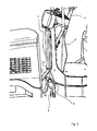
- FIG. 1 a construction machine 1, in particular a compacting machine is shown, which has a lifting device 2, which is arranged substantially at the position of a horizontal center of gravity of the construction machine 1.
- the lifting device is used to raise the construction machine 1 by means of a crane or other lifting device, for example, to load the construction machine on a transport vehicle or to unload from a transport vehicle.
- the lifting device 2 is connected to the lifting device (not shown) and can be lifted by this.
- the provision of the lifting device 2 at the substantially horizontal center of gravity of the construction machine 1 serves to avoid tilting of the construction machine when lifting as possible.
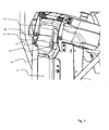
- FIG. 2 an enlarged view of the lifting device 2 is shown in a rest position.
- the lifting device 2 has a flexible support element 4 in the form of a flexible band with a rectangular cross-section. Other band cross sections or cross sections of the support member 4 are possible.
- the flexible band 4 is guided by a guide member 5 in the form of a channel which is fixed to a column with a control panel 6 of the construction machine.
- the channel is formed here by a metal tube.
- On the pillar also a climbing bar 15 is attached.
- the flexible band 4 is provided with a loop 7, which is held on a holding device 8.
- the holding device 8 has two fixedly attached to the construction machine holding elements with eyes through which a bolt 9 can be inserted so that the bolt passes through the loop.
- the guide element 5 is mounted substantially vertically above the holding device, so that in the attached state, the flexible band 4 extends from the holding device 8 through the guide member 5 is substantially straight.
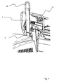
- FIG. 3 an upper end of the flexible band 4 is shown in a rest position.
- the upper end of the flexible band 4 is provided with a bracket 10, which is connected to a further loop 11 of the flexible band 4.
- the bracket 10 may also be provided an eyelet, a hook or other attachment element that is suitable to establish a connection with the lifting device.
- the flexible band 4 In the rest position, the flexible band 4 is displaced downwards by the guide element 5, so that the flexible band 4 can be in an unstretched state in a gap 12 of the construction machine between a lower end of the guide element 5 and the holding device 8.
- the bracket 10 At rest, the bracket 10 is folded down in a direction parallel to the flexible band 4 direction, and inserted into a holder 13, so that the bracket 10 is held securely against vibration and falling out.
- the bracket 13 is formed as a retaining clip with two folded ends that hold the bracket 10 against lateral displacement in the fixed state.
- the lower in the folded state of the bracket 10 lower end of the bracket 10 abuts an upper end of the guide member 5, so that the bracket 10 can not fall down from the retaining clip 13.
- the guide element 5 has, as in FIG. 2 and FIG. 3 illustrated, folded at both ends portions 14 to prevent the sliding of the flexible tape 4 by the guide member 5, a hooking of the tape 4 on the guide member 5 or abrasion of the flexible tape 4 on the guide member.
- the guide element 5 is designed so that its inner cross section is substantially adapted to the cross section of the flexible band 4. Since the flexible band 4 has a rectangular cross-section, preferably the cross-section of the guide element 5 is also provided at right angles, which allows the flexible band 4 to be moved freely through the guide element 5, but a twisting of the flexible band 4 in the guide element 5 does not allow.
- FIG. 4 the lifting device is shown in a position of use.
- the flexible band 4 is pulled through the guide member 5 and extends substantially straight from the (in FIG. 4 not shown) holding device 8 through the guide member 5 to the attachment element formed by the bracket 10.
- the guide element 5 serves to avoid tilting or rocking of the attached machine when lifting the construction machine.
- the length of the flexible band 4 is chosen so that when lifting the machine 1 no damage to the machine 1 by the lifter, in particular no damage to the control panel 6 and the climbing bracket 15 takes place.
- FIG. 5 the stretched state of the flexible band 4 between the holding device 8 and the guide member 5 is shown again in the position of use.
- FIG. 6 shows the flexible band 4 in a rest position, in which the bracket 10 is held in the retaining clip 13.
- a pivotable cover 16, which is disposed near the retaining clip 13, is shown in an open state.
- the cover 16 is pivoted so that it completely covers the retaining clip 13, the bracket 10 and the upper end of the flexible band 4 and extends substantially to the upper end of the guide element 5. This ensures that the lifting device 2 is protected during the operation of the machine from dirt and moisture, so that the life of the lifting device 2 is extended.
- a flexible band 4 as part of a lifting device 2 serves to avoid vibrations of the machine 1, a chattering of the flexible band 4 against components of the machine 1, whereby disturbing noises are generated.
- a corrosion-resistant band made of a plastic or a composite fiber material can be ensured with such a lifting device equal security, as it consists of permanently mounted lifting devices without a flexible band.
Landscapes
- Engineering & Computer Science (AREA)
- Mechanical Engineering (AREA)
- Agricultural Machines (AREA)
- Control And Safety Of Cranes (AREA)
- Transplanting Machines (AREA)
- Jib Cranes (AREA)
- Load-Engaging Elements For Cranes (AREA)
- Spinning Or Twisting Of Yarns (AREA)
- Cage And Drive Apparatuses For Elevators (AREA)
- Vehicle Cleaning, Maintenance, Repair, Refitting, And Outriggers (AREA)
Claims (14)
- Machine (1) avec un système de levage (2) pour lever la machine à l'aide d'un instrument de levage, le système de levage (2) comportant un élément porteur (4) flexible qui est fixé à une extrémité à la hauteur du centre de gravité horizontal de la machine (1) et qui comporte à une autre extrémité une possibilité d'attelage pour la liaison avec l'instrument de levage,
caractérisée en ce que
l'élément porteur (4) flexible est guidé mobile en coulissement par un élément de guidage (5) qui est disposé sensiblement à l'aplomb au-dessus du centre de gravité horizontal. - Machine (1) selon la revendication 1,
caractérisée en ce que
l'élément de guidage (5) est formé par un étrier. - Machine (1) selon la revendication 1,
caractérisée en ce que
l'élément de guidage (5) est formé par un canal. - Machine (1) selon la revendication 1,
caractérisée en ce que
l'élément de guidage (5) comporte à au moins une extrémité un tronçon courbé vers l'extérieur afin de réduire l'abrasion de l'élément porteur (4) flexible lors du passage de l'élément porteur (4) flexible. - Machine (1) selon la revendication 1 ou 2,
caractérisée en ce qu'
une section intérieure de l'élément de guidage (5) est adaptée à la forme de la section de l'élément porteur (4) flexible de telle sorte que l'élément porteur (4) flexible est immobilisé en rotation dans l'élément de guidage (5). - Machine (1) selon l'une quelconque des revendications 1 à 5,
caractérisée en ce que
l'élément porteur (4) flexible est apte à être mû dans une position de repos dans laquelle l'élément porteur (4) flexible est déplacé vers le centre de gravité par l'élément de guidage (5) jusqu'à ce que l'élément d'attelage (10) se situe à proximité d'une extrémité supérieure de l'élément de guidage (5) et dans une position d'utilisation dans laquelle l'élément porteur (4) flexible est tiré vers le haut de manière à être sensiblement étiré par l'élément de guidage (5) à partir du centre de gravité. - Machine (1) selon l'une quelconque des revendications précédentes,
caractérisée en ce que
l'élément d'attelage est conformé en forme d'étrier, d'oeillet ou de crochet, l'étrier étant retenu sur l'élément porteur (4) flexible, un dispositif de retenue (13) situé à proximité de l'extrémité supérieure de l'élément de guidage (5) étant prévu pour retenir le système d'attelage (10) dans la position de repos. - Machine (1) selon la revendication 7,
caractérisée en ce que
le dispositif de retenue est conçu de manière à retenir le système d'attelage (10) pivoté vers le bas dans le dispositif de retenue en position de repos. - Machine (1) selon la revendication 7 ou 8,
caractérisée en ce qu'
un système de recouvrement est prévu pour recouvrir l'élément d'attelage (13) retenu dans le dispositif de retenue en position de repos et pour retirer l'élément d'attelage (13) pour l'amener dans la position d'utilisation. - Machine (1) selon l'une quelconque des revendications 1 à 9,
caractérisée en ce que
le système de levage (2) comporte un dispositif de retenue (8) qui est fixé à la hauteur du centre de gravité horizontal de la machine (1), l'élément porteur (4) flexible comportant une boucle à l'une des extrémités, le dispositif de retenue (8) comprenant deux yeux permettant d'y faire passer un boulon de manière à ce que celui-ci traverse la boucle. - Machine (1) selon l'une quelconque des revendications 1 à 10,
caractérisée en ce que
le système de levage (2) comporte un dispositif de retenue (8) qui est fixé à la hauteur du centre de gravité horizontal de la machine (1), l'élément porteur (4) flexible étant relié au châssis à l'une des extrémités par un élément de liaison qui est fixé. - Machine (1) selon l'une quelconque des revendications 1 à 11,
caractérisée en ce que
l'élément porteur (4) flexible a la forme d'une bande. - Machine (1) selon l'une quelconque des revendications 1 à 12,
caractérisée en ce que
l'élément porteur (4) flexible est réalisé de manière à être résistant à la corrosion. - Machine (1) selon l'une quelconque des revendications 1 à 13,
caractérisée en ce que
l'élément porteur (4) flexible comporte une matière plastique ou un matériau en fibre composite.
Applications Claiming Priority (2)
| Application Number | Priority Date | Filing Date | Title |
|---|---|---|---|
| DE202004004706U | 2004-03-25 | ||
| DE202004004706U DE202004004706U1 (de) | 2004-03-25 | 2004-03-25 | Maschine mit einer Hebeeinrichtung |
Publications (3)
| Publication Number | Publication Date |
|---|---|
| EP1580070A2 EP1580070A2 (fr) | 2005-09-28 |
| EP1580070A3 EP1580070A3 (fr) | 2007-02-28 |
| EP1580070B1 true EP1580070B1 (fr) | 2008-10-29 |
Family
ID=34854227
Family Applications (1)
| Application Number | Title | Priority Date | Filing Date |
|---|---|---|---|
| EP05006569A Expired - Lifetime EP1580070B1 (fr) | 2004-03-25 | 2005-03-24 | Machine équipée d'un dispositif de levage |
Country Status (4)
| Country | Link |
|---|---|
| US (1) | US7192049B2 (fr) |
| EP (1) | EP1580070B1 (fr) |
| AT (1) | ATE412554T1 (fr) |
| DE (2) | DE202004004706U1 (fr) |
Families Citing this family (6)
| Publication number | Priority date | Publication date | Assignee | Title |
|---|---|---|---|---|
| US8376655B2 (en) * | 2008-10-03 | 2013-02-19 | Caterpillar Paving Products Inc. | Compactor with smooth hose routing |
| USD602506S1 (en) | 2008-10-03 | 2009-10-20 | Caterpillar Paving Products Inc. | Compactor |
| USD602048S1 (en) | 2008-10-03 | 2009-10-13 | Caterpillar Paving Products Inc. | Extension plate |
| US7857544B2 (en) * | 2008-10-03 | 2010-12-28 | Caterpillar Inc | Extension plate for a compactor |
| US8061747B2 (en) * | 2008-11-20 | 2011-11-22 | Alcoa Inc. | Systems and methods for lifting a vehicle |
| US9016741B1 (en) | 2014-08-22 | 2015-04-28 | Hendrick Motorsports Performance Group, LLC | System for lifting, moving and transporting a vehicle via multiple slings connected to a common lifting vertex, and method of retrofitting a vehicle to facilitate lifting |
Family Cites Families (6)
| Publication number | Priority date | Publication date | Assignee | Title |
|---|---|---|---|---|
| US3602544A (en) * | 1969-01-29 | 1971-08-31 | United Aircraft Corp | Universal,heavy-duty sling |
| US3781054A (en) * | 1972-10-24 | 1973-12-25 | C Cole | Beam arrangement for handling heavy elongate objects by power machinery |
| DE2818539A1 (de) * | 1978-04-27 | 1979-11-08 | Brueggemann & Brand Kg | Bausatz fuer lastenaufnahmesystem von hubschrauber-aussenlasten |
| US5263687A (en) * | 1991-09-27 | 1993-11-23 | Garbiso Michael J | Automobile hardtop storage apparatus |
| US5752733A (en) * | 1995-03-24 | 1998-05-19 | Marshall; Steven R. | Adjustable strap assembly for raising, lowering and transporting outboard motors and similar heavy bulky objects; and, methods of use thereof |
| US6232576B1 (en) * | 1998-12-10 | 2001-05-15 | Illinois Tool Works Inc. | Moveable lifting eye mechanism |
-
2004
- 2004-03-25 DE DE202004004706U patent/DE202004004706U1/de not_active Expired - Lifetime
-
2005
- 2005-03-24 AT AT05006569T patent/ATE412554T1/de not_active IP Right Cessation
- 2005-03-24 EP EP05006569A patent/EP1580070B1/fr not_active Expired - Lifetime
- 2005-03-24 DE DE502005005771T patent/DE502005005771D1/de not_active Expired - Lifetime
- 2005-03-24 US US11/087,817 patent/US7192049B2/en not_active Expired - Fee Related
Also Published As
| Publication number | Publication date |
|---|---|
| EP1580070A2 (fr) | 2005-09-28 |
| ATE412554T1 (de) | 2008-11-15 |
| EP1580070A3 (fr) | 2007-02-28 |
| US20050232739A1 (en) | 2005-10-20 |
| US7192049B2 (en) | 2007-03-20 |
| DE202004004706U1 (de) | 2005-09-08 |
| DE502005005771D1 (de) | 2008-12-11 |
Similar Documents
| Publication | Publication Date | Title |
|---|---|---|
| DE68909281T2 (de) | Verstellbare Säule für ein Lastkraftfahrzeug mit verschiebbarer Abdeckung. | |
| DE10339449B4 (de) | Fahrzeuglastenträger für ein Kraftfahrzeug | |
| EP3059119B1 (fr) | Point d'amarrage | |
| EP2786940A1 (fr) | Station de chargement pour sacs de transport pour le transport suspendu de marchandises | |
| DE202004009782U1 (de) | Kran-Gitterausleger und Kran | |
| EP1580070B1 (fr) | Machine équipée d'un dispositif de levage | |
| DE2759085A1 (de) | Fangvorrichtung fuer eine mindestens ein seil aufweisende hubvorrichtung | |
| DE102013004820B4 (de) | Halterungsvorrichtung zum Lagern von Haltestangen an einem Kran | |
| DE202015005847U1 (de) | Ladungssicherungsvorrichtung für landwirtschaftliche Transportwagen | |
| DE102017000389B4 (de) | Kranausleger, Kran mit einem solchen Kranausleger und Verfahren zum Anbringen einer Abspannstütze an einem solchen Kranausleger | |
| DE202008008417U1 (de) | Verriegelung zum Verriegeln eines Containers auf einer Auflage | |
| DE202008015659U1 (de) | Kranspitze für einen Ladekran | |
| DE202019103087U1 (de) | Transportvorrichtung mit translatorisch beweglichem Verstellelement | |
| DE102004019188A1 (de) | Haltevorrichtung zur Aufnahme eines mobilen Endgerätes/Bildschirmes | |
| EP3753787A1 (fr) | Véhicule automobile doté d'un recouvrement de compartiment pour loger des marchandises | |
| DE3839522C1 (en) | Device for fixing the unused upper link of a hydraulic three-point mounting apparatus on farm tractors | |
| DE19852858C2 (de) | Lastentragvorrichtung für Hebezeuge | |
| DE2649795B2 (de) | Sicherheitshaken | |
| DE102009038540B3 (de) | Haken, insbesondere für Sicherheitseinrichtungen, wie Fallschutzläufer | |
| EP3378821A1 (fr) | Dispositif de protection de personnes dans une cage d'ascenseur contre la chute éventuelle d'objets | |
| DE102009032426B3 (de) | Vorrichtung zur Montage und/oder Demontage von Ballast an einem Kran und Turmdrehkran mit einer derartigen Vorrichtung | |
| DE2630306C2 (de) | Schutzbezug für Lastaufnahmehaken | |
| DE3425016A1 (de) | Schiebeverdeck-planengestell | |
| DE102015109172A1 (de) | Nutzfahrzeugaufbau mit einer Plane, Nutzfahrzeug mit einem derartigen Nutzfahrzeugaufbau und Verfahren zur Herstellung eines Nutzfahrzeugaufbaus | |
| DE60307330T2 (de) | Seitliches Fahrschutzsystem |
Legal Events
| Date | Code | Title | Description |
|---|---|---|---|
| PUAI | Public reference made under article 153(3) epc to a published international application that has entered the european phase |
Free format text: ORIGINAL CODE: 0009012 |
|
| AK | Designated contracting states |
Kind code of ref document: A2 Designated state(s): AT BE BG CH CY CZ DE DK EE ES FI FR GB GR HU IE IS IT LI LT LU MC NL PL PT RO SE SI SK TR |
|
| AX | Request for extension of the european patent |
Extension state: AL BA HR LV MK YU |
|
| PUAL | Search report despatched |
Free format text: ORIGINAL CODE: 0009013 |
|
| AK | Designated contracting states |
Kind code of ref document: A3 Designated state(s): AT BE BG CH CY CZ DE DK EE ES FI FR GB GR HU IE IS IT LI LT LU MC NL PL PT RO SE SI SK TR |
|
| AX | Request for extension of the european patent |
Extension state: AL BA HR LV MK YU |
|
| RIC1 | Information provided on ipc code assigned before grant |
Ipc: B66C 1/20 20060101ALI20070122BHEP Ipc: B60P 1/00 20060101ALI20070122BHEP Ipc: B60P 3/06 20060101AFI20070122BHEP |
|
| 17P | Request for examination filed |
Effective date: 20070802 |
|
| 17Q | First examination report despatched |
Effective date: 20070919 |
|
| AKX | Designation fees paid |
Designated state(s): AT BE BG CH CY CZ DE DK EE ES FI FR GB GR HU IE IS IT LI LT LU MC NL PL PT RO SE SI SK TR |
|
| GRAP | Despatch of communication of intention to grant a patent |
Free format text: ORIGINAL CODE: EPIDOSNIGR1 |
|
| GRAS | Grant fee paid |
Free format text: ORIGINAL CODE: EPIDOSNIGR3 |
|
| GRAA | (expected) grant |
Free format text: ORIGINAL CODE: 0009210 |
|
| AK | Designated contracting states |
Kind code of ref document: B1 Designated state(s): AT BE BG CH CY CZ DE DK EE ES FI FR GB GR HU IE IS IT LI LT LU MC NL PL PT RO SE SI SK TR |
|
| REG | Reference to a national code |
Ref country code: GB Ref legal event code: FG4D Free format text: NOT ENGLISH |
|
| REG | Reference to a national code |
Ref country code: CH Ref legal event code: EP |
|
| REG | Reference to a national code |
Ref country code: CH Ref legal event code: NV Representative=s name: ROTTMANN, ZIMMERMANN + PARTNER AG |
|
| REG | Reference to a national code |
Ref country code: IE Ref legal event code: FG4D Free format text: LANGUAGE OF EP DOCUMENT: GERMAN |
|
| REF | Corresponds to: |
Ref document number: 502005005771 Country of ref document: DE Date of ref document: 20081211 Kind code of ref document: P |
|
| NLV1 | Nl: lapsed or annulled due to failure to fulfill the requirements of art. 29p and 29m of the patents act | ||
| LTIE | Lt: invalidation of european patent or patent extension |
Effective date: 20081029 |
|
| PG25 | Lapsed in a contracting state [announced via postgrant information from national office to epo] |
Ref country code: ES Free format text: LAPSE BECAUSE OF FAILURE TO SUBMIT A TRANSLATION OF THE DESCRIPTION OR TO PAY THE FEE WITHIN THE PRESCRIBED TIME-LIMIT Effective date: 20090209 Ref country code: BG Free format text: LAPSE BECAUSE OF FAILURE TO SUBMIT A TRANSLATION OF THE DESCRIPTION OR TO PAY THE FEE WITHIN THE PRESCRIBED TIME-LIMIT Effective date: 20090129 Ref country code: LT Free format text: LAPSE BECAUSE OF FAILURE TO SUBMIT A TRANSLATION OF THE DESCRIPTION OR TO PAY THE FEE WITHIN THE PRESCRIBED TIME-LIMIT Effective date: 20081029 |
|
| PG25 | Lapsed in a contracting state [announced via postgrant information from national office to epo] |
Ref country code: FI Free format text: LAPSE BECAUSE OF FAILURE TO SUBMIT A TRANSLATION OF THE DESCRIPTION OR TO PAY THE FEE WITHIN THE PRESCRIBED TIME-LIMIT Effective date: 20081029 Ref country code: SI Free format text: LAPSE BECAUSE OF FAILURE TO SUBMIT A TRANSLATION OF THE DESCRIPTION OR TO PAY THE FEE WITHIN THE PRESCRIBED TIME-LIMIT Effective date: 20081029 Ref country code: PT Free format text: LAPSE BECAUSE OF FAILURE TO SUBMIT A TRANSLATION OF THE DESCRIPTION OR TO PAY THE FEE WITHIN THE PRESCRIBED TIME-LIMIT Effective date: 20090330 Ref country code: PL Free format text: LAPSE BECAUSE OF FAILURE TO SUBMIT A TRANSLATION OF THE DESCRIPTION OR TO PAY THE FEE WITHIN THE PRESCRIBED TIME-LIMIT Effective date: 20081029 Ref country code: NL Free format text: LAPSE BECAUSE OF FAILURE TO SUBMIT A TRANSLATION OF THE DESCRIPTION OR TO PAY THE FEE WITHIN THE PRESCRIBED TIME-LIMIT Effective date: 20081029 Ref country code: IS Free format text: LAPSE BECAUSE OF FAILURE TO SUBMIT A TRANSLATION OF THE DESCRIPTION OR TO PAY THE FEE WITHIN THE PRESCRIBED TIME-LIMIT Effective date: 20090228 |
|
| REG | Reference to a national code |
Ref country code: IE Ref legal event code: FD4D |
|
| PG25 | Lapsed in a contracting state [announced via postgrant information from national office to epo] |
Ref country code: RO Free format text: LAPSE BECAUSE OF FAILURE TO SUBMIT A TRANSLATION OF THE DESCRIPTION OR TO PAY THE FEE WITHIN THE PRESCRIBED TIME-LIMIT Effective date: 20081029 Ref country code: IE Free format text: LAPSE BECAUSE OF FAILURE TO SUBMIT A TRANSLATION OF THE DESCRIPTION OR TO PAY THE FEE WITHIN THE PRESCRIBED TIME-LIMIT Effective date: 20081029 Ref country code: EE Free format text: LAPSE BECAUSE OF FAILURE TO SUBMIT A TRANSLATION OF THE DESCRIPTION OR TO PAY THE FEE WITHIN THE PRESCRIBED TIME-LIMIT Effective date: 20081029 Ref country code: DK Free format text: LAPSE BECAUSE OF FAILURE TO SUBMIT A TRANSLATION OF THE DESCRIPTION OR TO PAY THE FEE WITHIN THE PRESCRIBED TIME-LIMIT Effective date: 20081029 |
|
| PG25 | Lapsed in a contracting state [announced via postgrant information from national office to epo] |
Ref country code: SE Free format text: LAPSE BECAUSE OF FAILURE TO SUBMIT A TRANSLATION OF THE DESCRIPTION OR TO PAY THE FEE WITHIN THE PRESCRIBED TIME-LIMIT Effective date: 20090129 |
|
| PGFP | Annual fee paid to national office [announced via postgrant information from national office to epo] |
Ref country code: IT Payment date: 20090327 Year of fee payment: 5 |
|
| PLBE | No opposition filed within time limit |
Free format text: ORIGINAL CODE: 0009261 |
|
| STAA | Information on the status of an ep patent application or granted ep patent |
Free format text: STATUS: NO OPPOSITION FILED WITHIN TIME LIMIT |
|
| BERE | Be: lapsed |
Owner name: BOMAG G.M.B.H. Effective date: 20090331 |
|
| PG25 | Lapsed in a contracting state [announced via postgrant information from national office to epo] |
Ref country code: SK Free format text: LAPSE BECAUSE OF FAILURE TO SUBMIT A TRANSLATION OF THE DESCRIPTION OR TO PAY THE FEE WITHIN THE PRESCRIBED TIME-LIMIT Effective date: 20081029 |
|
| 26N | No opposition filed |
Effective date: 20090730 |
|
| PG25 | Lapsed in a contracting state [announced via postgrant information from national office to epo] |
Ref country code: MC Free format text: LAPSE BECAUSE OF NON-PAYMENT OF DUE FEES Effective date: 20090331 |
|
| PGFP | Annual fee paid to national office [announced via postgrant information from national office to epo] |
Ref country code: FR Payment date: 20090317 Year of fee payment: 5 |
|
| PGFP | Annual fee paid to national office [announced via postgrant information from national office to epo] |
Ref country code: GB Payment date: 20090403 Year of fee payment: 5 |
|
| PG25 | Lapsed in a contracting state [announced via postgrant information from national office to epo] |
Ref country code: BE Free format text: LAPSE BECAUSE OF NON-PAYMENT OF DUE FEES Effective date: 20090331 |
|
| PGFP | Annual fee paid to national office [announced via postgrant information from national office to epo] |
Ref country code: CH Payment date: 20100309 Year of fee payment: 6 Ref country code: CZ Payment date: 20100318 Year of fee payment: 6 |
|
| PG25 | Lapsed in a contracting state [announced via postgrant information from national office to epo] |
Ref country code: AT Free format text: LAPSE BECAUSE OF NON-PAYMENT OF DUE FEES Effective date: 20090324 |
|
| PG25 | Lapsed in a contracting state [announced via postgrant information from national office to epo] |
Ref country code: GR Free format text: LAPSE BECAUSE OF FAILURE TO SUBMIT A TRANSLATION OF THE DESCRIPTION OR TO PAY THE FEE WITHIN THE PRESCRIBED TIME-LIMIT Effective date: 20090130 |
|
| GBPC | Gb: european patent ceased through non-payment of renewal fee |
Effective date: 20100324 |
|
| REG | Reference to a national code |
Ref country code: FR Ref legal event code: ST Effective date: 20101130 |
|
| PG25 | Lapsed in a contracting state [announced via postgrant information from national office to epo] |
Ref country code: FR Free format text: LAPSE BECAUSE OF NON-PAYMENT OF DUE FEES Effective date: 20100331 |
|
| PG25 | Lapsed in a contracting state [announced via postgrant information from national office to epo] |
Ref country code: IT Free format text: LAPSE BECAUSE OF NON-PAYMENT OF DUE FEES Effective date: 20100324 Ref country code: GB Free format text: LAPSE BECAUSE OF NON-PAYMENT OF DUE FEES Effective date: 20100324 |
|
| PG25 | Lapsed in a contracting state [announced via postgrant information from national office to epo] |
Ref country code: LU Free format text: LAPSE BECAUSE OF NON-PAYMENT OF DUE FEES Effective date: 20090324 |
|
| PG25 | Lapsed in a contracting state [announced via postgrant information from national office to epo] |
Ref country code: HU Free format text: LAPSE BECAUSE OF FAILURE TO SUBMIT A TRANSLATION OF THE DESCRIPTION OR TO PAY THE FEE WITHIN THE PRESCRIBED TIME-LIMIT Effective date: 20090430 |
|
| PG25 | Lapsed in a contracting state [announced via postgrant information from national office to epo] |
Ref country code: TR Free format text: LAPSE BECAUSE OF FAILURE TO SUBMIT A TRANSLATION OF THE DESCRIPTION OR TO PAY THE FEE WITHIN THE PRESCRIBED TIME-LIMIT Effective date: 20081029 |
|
| REG | Reference to a national code |
Ref country code: CH Ref legal event code: PFA Owner name: BOMAG GMBH Free format text: BOMAG GMBH#HELLERWALD#56154 BOPPARD (DE) -TRANSFER TO- BOMAG GMBH#HELLERWALD#56154 BOPPARD (DE) |
|
| PG25 | Lapsed in a contracting state [announced via postgrant information from national office to epo] |
Ref country code: CY Free format text: LAPSE BECAUSE OF FAILURE TO SUBMIT A TRANSLATION OF THE DESCRIPTION OR TO PAY THE FEE WITHIN THE PRESCRIBED TIME-LIMIT Effective date: 20081029 |
|
| REG | Reference to a national code |
Ref country code: CH Ref legal event code: PL |
|
| PG25 | Lapsed in a contracting state [announced via postgrant information from national office to epo] |
Ref country code: LI Free format text: LAPSE BECAUSE OF NON-PAYMENT OF DUE FEES Effective date: 20110331 Ref country code: CZ Free format text: LAPSE BECAUSE OF NON-PAYMENT OF DUE FEES Effective date: 20110324 Ref country code: CH Free format text: LAPSE BECAUSE OF NON-PAYMENT OF DUE FEES Effective date: 20110331 |
|
| PGFP | Annual fee paid to national office [announced via postgrant information from national office to epo] |
Ref country code: DE Payment date: 20140305 Year of fee payment: 10 |
|
| REG | Reference to a national code |
Ref country code: DE Ref legal event code: R119 Ref document number: 502005005771 Country of ref document: DE |
|
| PG25 | Lapsed in a contracting state [announced via postgrant information from national office to epo] |
Ref country code: DE Free format text: LAPSE BECAUSE OF NON-PAYMENT OF DUE FEES Effective date: 20151001 |