EP1579124B1 - Elektromechanisch betätigbare feststellbremse - Google Patents
Elektromechanisch betätigbare feststellbremse Download PDFInfo
- Publication number
- EP1579124B1 EP1579124B1 EP03789204.9A EP03789204A EP1579124B1 EP 1579124 B1 EP1579124 B1 EP 1579124B1 EP 03789204 A EP03789204 A EP 03789204A EP 1579124 B1 EP1579124 B1 EP 1579124B1
- Authority
- EP
- European Patent Office
- Prior art keywords
- brake
- electromechanical actuator
- parking brake
- drum
- threaded nut
- Prior art date
- Legal status (The legal status is an assumption and is not a legal conclusion. Google has not performed a legal analysis and makes no representation as to the accuracy of the status listed.)
- Expired - Lifetime
Links
- 238000000034 method Methods 0.000 claims description 3
- 238000009434 installation Methods 0.000 claims 1
- 230000020347 spindle assembly Effects 0.000 description 3
- 238000001514 detection method Methods 0.000 description 1
- 238000004519 manufacturing process Methods 0.000 description 1
Images


Classifications
-
- F—MECHANICAL ENGINEERING; LIGHTING; HEATING; WEAPONS; BLASTING
- F16—ENGINEERING ELEMENTS AND UNITS; GENERAL MEASURES FOR PRODUCING AND MAINTAINING EFFECTIVE FUNCTIONING OF MACHINES OR INSTALLATIONS; THERMAL INSULATION IN GENERAL
- F16D—COUPLINGS FOR TRANSMITTING ROTATION; CLUTCHES; BRAKES
- F16D51/00—Brakes with outwardly-movable braking members co-operating with the inner surface of a drum or the like
- F16D51/46—Self-tightening brakes with pivoted brake shoes, i.e. the braked member increases the braking action
- F16D51/48—Self-tightening brakes with pivoted brake shoes, i.e. the braked member increases the braking action with two linked or directly-interacting brake shoes
- F16D51/50—Self-tightening brakes with pivoted brake shoes, i.e. the braked member increases the braking action with two linked or directly-interacting brake shoes mechanically actuated
-
- F—MECHANICAL ENGINEERING; LIGHTING; HEATING; WEAPONS; BLASTING
- F16—ENGINEERING ELEMENTS AND UNITS; GENERAL MEASURES FOR PRODUCING AND MAINTAINING EFFECTIVE FUNCTIONING OF MACHINES OR INSTALLATIONS; THERMAL INSULATION IN GENERAL
- F16D—COUPLINGS FOR TRANSMITTING ROTATION; CLUTCHES; BRAKES
- F16D65/00—Parts or details
- F16D65/14—Actuating mechanisms for brakes; Means for initiating operation at a predetermined position
- F16D65/16—Actuating mechanisms for brakes; Means for initiating operation at a predetermined position arranged in or on the brake
- F16D65/22—Actuating mechanisms for brakes; Means for initiating operation at a predetermined position arranged in or on the brake adapted for pressing members apart, e.g. for drum brakes
-
- F—MECHANICAL ENGINEERING; LIGHTING; HEATING; WEAPONS; BLASTING
- F16—ENGINEERING ELEMENTS AND UNITS; GENERAL MEASURES FOR PRODUCING AND MAINTAINING EFFECTIVE FUNCTIONING OF MACHINES OR INSTALLATIONS; THERMAL INSULATION IN GENERAL
- F16D—COUPLINGS FOR TRANSMITTING ROTATION; CLUTCHES; BRAKES
- F16D65/00—Parts or details
- F16D65/38—Slack adjusters
- F16D2065/386—Slack adjusters driven electrically
-
- F—MECHANICAL ENGINEERING; LIGHTING; HEATING; WEAPONS; BLASTING
- F16—ENGINEERING ELEMENTS AND UNITS; GENERAL MEASURES FOR PRODUCING AND MAINTAINING EFFECTIVE FUNCTIONING OF MACHINES OR INSTALLATIONS; THERMAL INSULATION IN GENERAL
- F16D—COUPLINGS FOR TRANSMITTING ROTATION; CLUTCHES; BRAKES
- F16D66/00—Arrangements for monitoring working conditions, e.g. wear, temperature
- F16D2066/003—Position, angle or speed
-
- F—MECHANICAL ENGINEERING; LIGHTING; HEATING; WEAPONS; BLASTING
- F16—ENGINEERING ELEMENTS AND UNITS; GENERAL MEASURES FOR PRODUCING AND MAINTAINING EFFECTIVE FUNCTIONING OF MACHINES OR INSTALLATIONS; THERMAL INSULATION IN GENERAL
- F16D—COUPLINGS FOR TRANSMITTING ROTATION; CLUTCHES; BRAKES
- F16D2121/00—Type of actuator operation force
- F16D2121/18—Electric or magnetic
- F16D2121/24—Electric or magnetic using motors
-
- F—MECHANICAL ENGINEERING; LIGHTING; HEATING; WEAPONS; BLASTING
- F16—ENGINEERING ELEMENTS AND UNITS; GENERAL MEASURES FOR PRODUCING AND MAINTAINING EFFECTIVE FUNCTIONING OF MACHINES OR INSTALLATIONS; THERMAL INSULATION IN GENERAL
- F16D—COUPLINGS FOR TRANSMITTING ROTATION; CLUTCHES; BRAKES
- F16D2125/00—Components of actuators
- F16D2125/18—Mechanical mechanisms
- F16D2125/20—Mechanical mechanisms converting rotation to linear movement or vice versa
- F16D2125/34—Mechanical mechanisms converting rotation to linear movement or vice versa acting in the direction of the axis of rotation
- F16D2125/40—Screw-and-nut
-
- F—MECHANICAL ENGINEERING; LIGHTING; HEATING; WEAPONS; BLASTING
- F16—ENGINEERING ELEMENTS AND UNITS; GENERAL MEASURES FOR PRODUCING AND MAINTAINING EFFECTIVE FUNCTIONING OF MACHINES OR INSTALLATIONS; THERMAL INSULATION IN GENERAL
- F16D—COUPLINGS FOR TRANSMITTING ROTATION; CLUTCHES; BRAKES
- F16D2125/00—Components of actuators
- F16D2125/18—Mechanical mechanisms
- F16D2125/44—Mechanical mechanisms transmitting rotation
- F16D2125/46—Rotating members in mutual engagement
- F16D2125/48—Rotating members in mutual engagement with parallel stationary axes, e.g. spur gears
-
- F—MECHANICAL ENGINEERING; LIGHTING; HEATING; WEAPONS; BLASTING
- F16—ENGINEERING ELEMENTS AND UNITS; GENERAL MEASURES FOR PRODUCING AND MAINTAINING EFFECTIVE FUNCTIONING OF MACHINES OR INSTALLATIONS; THERMAL INSULATION IN GENERAL
- F16D—COUPLINGS FOR TRANSMITTING ROTATION; CLUTCHES; BRAKES
- F16D2125/00—Components of actuators
- F16D2125/18—Mechanical mechanisms
- F16D2125/44—Mechanical mechanisms transmitting rotation
- F16D2125/46—Rotating members in mutual engagement
- F16D2125/52—Rotating members in mutual engagement with non-parallel stationary axes, e.g. worm or bevel gears
Definitions
- the present invention relates to an electromechanically actuated parking brake for motor vehicles, having the features of the preamble of claim 1.
- a parking brake is off US 4928543A known.
- a drum brake that performs the function of a "simplex" drum brake during service braking and performs the function of a "duo-servo" type drum brake during parking brake operations.
- an electromechanically actuated device is provided in the known drum brake, which cancels the effect of the supporting device of the two brake shoes and realizes a floating storage.
- the brake shoes are simultaneously brought into engagement with the brake drum for carrying out a parking brake operation.
- the brake shoes during a parking brake operation are adjustable only by a single predetermined distance, which is not sufficient in particular with worn brake pads to achieve the required clamping force.
- the threaded nut has a straight toothing, which forms a fferradgetriebe with a driven by the electromechanical actuator helical gear.
- the threaded nut has a spur toothing, which forms a spur gear with a driven by the electromechanical actuator gear.
- the electromechanical actuator is mounted radially to the brake drum at an angle adapted to the available space relative to a plane which is perpendicular to the axis of the brake drum.
- the electromechanical actuator is mounted tangentially to the brake drum.
- a reduction gear is provided between the electromechanical actuator and the helical gear.
- a particularly advantageous development of the subject invention provides that the electromechanical actuator is formed by an electric motor having a sensor for detecting has the position of its rotor. By this measure, the lining wear of the brake shoes can be determined.
- the brake drum is arranged in the central region of a brake disc.
- the inventive electromechanically actuated parking brake shown in the drawing consists essentially of a known drum brake type "duo-servo", and an electromechanical actuator 15.
- the drum brake type “duo-servo” has a brake drum 5, provided with friction surfaces Pair of brake shoes 3, 4 and an expanding lock 2, which is the friction surfaces of the brake shoes 3, 4 with the inside the brake drum 5 can engage.
- Characteristic of the drum brake type “Duo-Servo” is a freely movable or floating support device 14, which is opposite to the expansion lock 2 and between the Bremsbakken 3, 4 is arranged.
- the support device 14 is combined with an adjusting device.
- the electromechanical actuator 15 is mounted radially to the brake drum 5 on a wheel carrier, not shown, preferably at an angle of about 30 ° relative to the illustrated sectional plane, which is particularly advantageous in terms of limited space conditions on the wheel.
- the electromechanical actuator 15 drives via a non-descript reduction gear 12 a fferrad 1, whereby the already mentioned Sp Drschsch 2, based on Fig.2 will be explained in more detail, is operated.
- the expanding lock 2 is designed as a threaded nut spindle arrangement 8, the threaded nut 6 has on the outer surface a toothing which is parallel to the axis of the threaded nut 6.
- the just mentioned helical gear 1 forms a helical gear.
- the threaded nut 6 is set in a rotational movement. Due to this rotational movement of the threaded nut 6, the spindle 7 of the threaded nut spindle arrangement 8 performs a translational movement and brings the two brake shoes 3, 4 with the desired clamping force even with worn brake pads with the brake drum 5 into engagement.
- either the reduction gear 12 or the threaded nut spindle assembly 8 is self-locking. By this measure remain the brake shoes 3, 4 in the de-energized state of the electromechanical actuator 15 with the brake drum 5 into engagement.
- the already mentioned electromechanical actuator 15 is formed by an electric motor and has a sensor, not shown, which detects the position of its rotor. This makes it possible to determine how many revolutions of the rotor and thus both the helical gear 1 and the threaded nut 6 complete. With the help of this information, a very reliable working pad wear detection of the brake shoes 3, 4 can be realized.
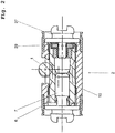
- the expanding lock 2 is described below with reference to Fig.2 explained in more detail.
- the expanding lock 2 is formed by a threaded nut spindle arrangement 8 whose threaded nut 6 is rotatably mounted in a housing 10 of the expanding lock 2 with the aid of an axial bearing 29.
- the spur toothing on the outer surface of the threaded nut 6 is indicated only schematically and standing in engagement with her ringrad 1 shown only in section.
- the electromechanical actuator drives the helical gear 1
- the threaded nut 6, as already described is set in rotation.
- the spindle 7 performs a translational movement in the drawing to the left and presses the first brake shoe 3 against the brake drum 5.
- the electromechanical actuator 15 is mounted tangentially to the brake drum 5 on a mudguard 9, which in turn is fixedly connected to the wheel carrier, not shown.
- This arrangement of the electromechanical actuator 15 is also advantageous in terms of limited space conditions on the wheel.
- the electromechanical actuator 15 drives a gear 11 via a reduction gear 22, whereby the expanding lock 2 is actuated and the two brake shoes 3, 4 are brought into engagement with the inside of the brake drum 5.
- the expansion lock 2 is in turn formed from a threaded nut spindle arrangement 18, as shown in particular in FIG Figure 4 is shown.
- the threaded nut 16 has on its outer surface a spur toothing and forms with the gear 11 a spur gear spur gear.
- the reduction gear 22 or the threaded nut spindle assembly 18 be designed to be self-locking, so that the set clamping force after switching off the electromechanical actuator 15 is maintained.
- the electromechanical actuator 15 with the brake shoes 3, 4, the support device 14 and the mudguard 9 form a preassembled module, which can be particularly easily mounted in the manufacture of motor vehicles.
- both described embodiments of the parking brake according to the invention can be combined with a hydraulic disc brake for service braking by the brake drum 5 arranged in the central region of a brake disc.
- This has the advantage that the parking brake according to the invention operated with a particularly cost-effective control of the electromechanical actuator 15 and the power requirement can be minimized to the electromechanical actuator 15.
Landscapes
- Engineering & Computer Science (AREA)
- General Engineering & Computer Science (AREA)
- Mechanical Engineering (AREA)
- Braking Arrangements (AREA)
Applications Claiming Priority (5)
| Application Number | Priority Date | Filing Date | Title |
|---|---|---|---|
| DE10261095 | 2002-12-20 | ||
| DE10261095 | 2002-12-20 | ||
| DE10343246 | 2003-09-17 | ||
| DE10343246 | 2003-09-17 | ||
| PCT/EP2003/013997 WO2004059189A1 (de) | 2002-12-20 | 2003-12-10 | Elektromechanisch betätigbare feststellbremse |
Publications (2)
| Publication Number | Publication Date |
|---|---|
| EP1579124A1 EP1579124A1 (de) | 2005-09-28 |
| EP1579124B1 true EP1579124B1 (de) | 2018-10-17 |
Family
ID=32683482
Family Applications (1)
| Application Number | Title | Priority Date | Filing Date |
|---|---|---|---|
| EP03789204.9A Expired - Lifetime EP1579124B1 (de) | 2002-12-20 | 2003-12-10 | Elektromechanisch betätigbare feststellbremse |
Country Status (6)
| Country | Link |
|---|---|
| US (1) | US20060278477A1 (da) |
| EP (1) | EP1579124B1 (da) |
| JP (1) | JP4800767B2 (da) |
| KR (1) | KR20050084449A (da) |
| BR (1) | BR0307758B1 (da) |
| WO (1) | WO2004059189A1 (da) |
Cited By (1)
| Publication number | Priority date | Publication date | Assignee | Title |
|---|---|---|---|---|
| DE102019207671B3 (de) * | 2019-05-24 | 2020-08-20 | Continental Teves Ag & Co. Ohg | Spreizeinrichtung für eine Trommelbremse |
Families Citing this family (32)
| Publication number | Priority date | Publication date | Assignee | Title |
|---|---|---|---|---|
| DE102004049434A1 (de) * | 2004-01-21 | 2005-10-06 | Continental Teves Ag & Co. Ohg | Elektromechanisch betätigbare Feststellbremse |
| WO2007089300A2 (en) * | 2005-10-31 | 2007-08-09 | Kelsey-Hayes Company | Electric actuator unit for a vehicle brake assembly |
| DE102008013747B4 (de) | 2007-03-16 | 2016-07-07 | Continental Teves Ag & Co. Ohg | Feststellbremse für Kraftfahrzeuge sowie Bremsbacke hierfür |
| EP2198180B1 (de) | 2007-09-05 | 2014-08-27 | Continental Teves AG & Co. oHG | Elektromechanisch betätigbare feststellbremse für kraftfahrzeuge und verfahren zur betätigung einer solchen |
| DE102008050215A1 (de) | 2008-10-02 | 2010-04-08 | Continental Teves Ag & Co. Ohg | Elektromechanisch betätigbare Feststellbremse für Kraftfahrzeuge |
| US9446748B2 (en) * | 2010-04-16 | 2016-09-20 | Gregory A Ward | Portable antilock brake system |
| JP5546491B2 (ja) * | 2011-03-31 | 2014-07-09 | 株式会社アドヴィックス | 電動駐車ブレーキ装置 |
| KR101421948B1 (ko) * | 2012-12-13 | 2014-07-22 | 현대자동차주식회사 | 전동식 파킹브레이크 엑추에이터 구조 |
| FR3013408B1 (fr) * | 2013-11-19 | 2015-12-25 | Chassis Brakes Int Bv | Frein a tambour fonctionnant en mode simplex et/ou en mode duo servo |
| DE102013224922A1 (de) * | 2013-12-04 | 2015-06-11 | Continental Teves Ag & Co. Ohg | Elektromechanisch betätigbare Trommelbremse |
| FR3016014B1 (fr) * | 2013-12-30 | 2017-03-31 | Chassis Brakes Int Bv | Actionneur avec systeme vis-ecrou irreversible, frein a tambour et dispositif de freinage ainsi equipes |
| FR3016016B1 (fr) * | 2013-12-30 | 2016-02-12 | Chassis Brakes Int Bv | Motoreducteur avec moteur electrique adaptable pour actionneur de frein a tambour |
| FR3016015B1 (fr) * | 2013-12-30 | 2017-03-31 | Chassis Brakes Int Bv | Motoreducteur a train epicycloidal et frein a tambour et dispositif de freinage ainsi equipes |
| US9476469B2 (en) | 2014-01-22 | 2016-10-25 | Akebono Brake Industry Co., Ltd | Electric drum or drum-in-hat park brake |
| JP6254697B2 (ja) * | 2014-06-26 | 2017-12-27 | 曙ブレーキ工業株式会社 | ドラムブレーキ装置 |
| KR101532231B1 (ko) * | 2014-07-23 | 2015-07-01 | 현대모비스 주식회사 | 차량용 제동장치 |
| KR20170023319A (ko) * | 2015-08-20 | 2017-03-03 | 현대모비스 주식회사 | 차량용 브레이크 |
| CN105299105A (zh) * | 2015-12-01 | 2016-02-03 | 潍坊埃锐制动系统有限公司 | 用于鼓式制动器的电子驻车制动装置 |
| CN107521489A (zh) * | 2016-06-21 | 2017-12-29 | 香宾 | 一种提高驾驶安全的道路辅助系统汽车 |
| KR101889455B1 (ko) * | 2016-10-17 | 2018-09-21 | 현대모비스 주식회사 | 전자식 주차 브레이크 장치 |
| US11060572B2 (en) * | 2017-02-07 | 2021-07-13 | ZF Active Safety US Inc. | Electric actuator assembly for a drum brake assembly |
| DE102017218219A1 (de) * | 2017-10-12 | 2019-04-18 | Continental Teves Ag & Co. Ohg | Spreizeinheit für Trommelbremse mit Verschleißwegnachstellung und die Trommelbremse |
| KR101988517B1 (ko) * | 2018-01-08 | 2019-06-13 | 주식회사 만도 | 차량용 로터리 댐퍼의 감쇠력 보상장치 |
| DE102018102848A1 (de) * | 2018-02-08 | 2019-08-08 | Brose Fahrzeugteile Gmbh & Co. Kommanditgesellschaft, Bamberg | Trommelbremse mit Bremselementen |
| KR20190128346A (ko) * | 2018-05-08 | 2019-11-18 | 주식회사 만도 | 드럼 일체형 파킹 브레이크 |
| FR3091324B1 (fr) * | 2018-12-27 | 2021-01-29 | Foundation Brakes France | Actionneur pour frein electromecanique a detecteur d’etat integre |
| US11339842B2 (en) | 2019-03-26 | 2022-05-24 | Akebono Brake Industry Co., Ltd. | Brake system with torque distributing assembly |
| KR102647979B1 (ko) * | 2019-04-12 | 2024-03-15 | 에이치엘만도 주식회사 | 전자식 주차 브레이크 |
| DE102019206031B4 (de) | 2019-04-26 | 2020-11-19 | Continental Teves Ag & Co. Ohg | Spreizeinrichtung für eine Trommelbremse |
| KR102258686B1 (ko) * | 2019-10-29 | 2021-05-31 | 현대모비스 주식회사 | 전자제어식 브레이크 장치 |
| KR102401766B1 (ko) | 2021-08-11 | 2022-05-25 | 주식회사 만도 | 전자기계식 브레이크 및 이를 구비하는 차량 |
| KR102403441B1 (ko) * | 2021-12-22 | 2022-05-30 | 주식회사 만도 | 전자기계식 드럼 브레이크 |
Citations (2)
| Publication number | Priority date | Publication date | Assignee | Title |
|---|---|---|---|---|
| US4793447A (en) * | 1986-12-23 | 1988-12-27 | Allied-Signal Inc. | Electrically operated disc brake |
| US6209689B1 (en) * | 1997-11-22 | 2001-04-03 | Continental Teves Ag & Co., Ohg | Method and system for actuating an electromechanically operable parking brake for automotive vehicles |
Family Cites Families (9)
| Publication number | Priority date | Publication date | Assignee | Title |
|---|---|---|---|---|
| US3809191A (en) * | 1969-08-04 | 1974-05-07 | Index Ind Inc | Auxiliary braking system |
| US4928543A (en) * | 1988-04-19 | 1990-05-29 | Allied-Signal Inc. | Electrically operated drum brake |
| JP3726443B2 (ja) * | 1997-09-29 | 2005-12-14 | トヨタ自動車株式会社 | 電動ブレーキ装置 |
| JP2000297833A (ja) * | 1999-04-15 | 2000-10-24 | Akebono Brake Ind Co Ltd | 電動式パーキングブレーキ |
| JP4335375B2 (ja) * | 1999-09-10 | 2009-09-30 | 豊生ブレーキ工業株式会社 | モータ駆動ドラムブレーキ用アクチュエータ |
| NL1013783C2 (nl) * | 1999-12-07 | 2001-06-08 | Skf Eng & Res Centre Bv | Trommelrem en elektrische actuator daarvoor. |
| JP2001173693A (ja) * | 1999-12-21 | 2001-06-26 | Hosei Brake Ind Ltd | モータ駆動ブレーキ用アクチュエータ |
| JP2001254770A (ja) * | 2000-03-13 | 2001-09-21 | Akebono Brake Ind Co Ltd | ドラムブレーキ装置におけるパーキング機構 |
| ITTO20011137A1 (it) * | 2001-12-07 | 2003-06-09 | Skf Ind Spa | Attuatore a doppia vite. |
-
2003
- 2003-12-10 KR KR1020057011640A patent/KR20050084449A/ko active Search and Examination
- 2003-12-10 US US10/540,165 patent/US20060278477A1/en not_active Abandoned
- 2003-12-10 JP JP2005509697A patent/JP4800767B2/ja not_active Expired - Fee Related
- 2003-12-10 BR BRPI0307758-6A patent/BR0307758B1/pt not_active IP Right Cessation
- 2003-12-10 WO PCT/EP2003/013997 patent/WO2004059189A1/de active Application Filing
- 2003-12-10 EP EP03789204.9A patent/EP1579124B1/de not_active Expired - Lifetime
Patent Citations (2)
| Publication number | Priority date | Publication date | Assignee | Title |
|---|---|---|---|---|
| US4793447A (en) * | 1986-12-23 | 1988-12-27 | Allied-Signal Inc. | Electrically operated disc brake |
| US6209689B1 (en) * | 1997-11-22 | 2001-04-03 | Continental Teves Ag & Co., Ohg | Method and system for actuating an electromechanically operable parking brake for automotive vehicles |
Cited By (1)
| Publication number | Priority date | Publication date | Assignee | Title |
|---|---|---|---|---|
| DE102019207671B3 (de) * | 2019-05-24 | 2020-08-20 | Continental Teves Ag & Co. Ohg | Spreizeinrichtung für eine Trommelbremse |
Also Published As
| Publication number | Publication date |
|---|---|
| BR0307758B1 (pt) | 2014-08-19 |
| US20060278477A1 (en) | 2006-12-14 |
| BR0307758A (pt) | 2004-12-21 |
| EP1579124A1 (de) | 2005-09-28 |
| WO2004059189A1 (de) | 2004-07-15 |
| JP2006511773A (ja) | 2006-04-06 |
| KR20050084449A (ko) | 2005-08-26 |
| JP4800767B2 (ja) | 2011-10-26 |
Similar Documents
| Publication | Publication Date | Title |
|---|---|---|
| EP1579124B1 (de) | Elektromechanisch betätigbare feststellbremse | |
| EP1025372B1 (de) | Bremsenanordnung für ein landfahrzeug | |
| DE10102685B4 (de) | Betätigungsmechanismus mit Kraftsensor für eine Bremse | |
| DE10112570B4 (de) | Elektrisch betätigbare Scheibenbremse | |
| EP1692413B1 (de) | Selbstverstärkende elektromechanische fahrzeugbremse | |
| DE19621533A1 (de) | Elektromotorische Bremsvorrichtung | |
| DE102012217275A1 (de) | Scheibenbremsvorrichtung | |
| DE112012001273T5 (de) | Elektrische Bremse mit Parkmechanismus | |
| EP1706298B1 (de) | Elektromechanisch betätigbare feststellbremse | |
| EP1664573B1 (de) | Azimutbremse fuer windkraftanlagen | |
| DE102006012440A1 (de) | Bremse mit Spindel und Kurvenscheiben-Anordnung | |
| DE2402469B2 (de) | Selbsttätige Nachstellvorrichtung für eine mechanisch betätigbare Teilbelag-Scheibenbremse, insbesondere Schwimmsattel-Scheibenbremse | |
| EP3487735B1 (de) | Fahrzeugbetriebsbremse mit elektromechanisch-hydraulischer bremskraftverstärkung | |
| EP3077694A2 (de) | Elektromotorisch betreibbares trommelbremsmodul | |
| DE102011086152B4 (de) | Bremseinrichtung | |
| DE10317949B4 (de) | Elektrisch betätigte Bremsanordnung für ein Getriebe | |
| EP1307666A1 (de) | Scheibenbremse | |
| DE102005056221A1 (de) | Elektromechanisch betätigbare Feststellbremse | |
| EP2467611B1 (de) | Radial wirkende rotationsarretierung | |
| DE102007054498A1 (de) | Elektromechanisch betätigbare Feststellbremse | |
| WO2007115900A1 (de) | Selbstverstärkende elektromechanische teilbelagscheibenbremse | |
| EP2002141B1 (de) | Selbstverstärkende scheibenbremse und verfahren zu deren ansteuerung | |
| EP1790872A1 (de) | Scheibenbremse, insbesondere für ein Nutzfahrzeug | |
| DE10227828B4 (de) | Elektrisch betätigbare Kraftfahrzeug-Scheibenbremse | |
| WO2013156583A1 (de) | Bremsvorrichtung für eine direkt elektromechanisch aktuierte planetengetriebeanordnung eines sitzverstellmechanismus und verfahren zum betrieb einer bremsvorrichtung |
Legal Events
| Date | Code | Title | Description |
|---|---|---|---|
| PUAI | Public reference made under article 153(3) epc to a published international application that has entered the european phase |
Free format text: ORIGINAL CODE: 0009012 |
|
| 17P | Request for examination filed |
Effective date: 20050720 |
|
| AK | Designated contracting states |
Kind code of ref document: A1 Designated state(s): AT BE BG CH CY CZ DE DK EE ES FI FR GB GR HU IE IT LI LU MC NL PT RO SE SI SK TR |
|
| AX | Request for extension of the european patent |
Extension state: AL LT LV MK |
|
| DAX | Request for extension of the european patent (deleted) | ||
| RBV | Designated contracting states (corrected) |
Designated state(s): CZ DE ES FR GB IT |
|
| 17Q | First examination report despatched |
Effective date: 20100615 |
|
| REG | Reference to a national code |
Ref country code: DE Ref legal event code: R079 Ref document number: 50315793 Country of ref document: DE Free format text: PREVIOUS MAIN CLASS: F16D0065270000 Ipc: F16D0065140000 |
|
| GRAP | Despatch of communication of intention to grant a patent |
Free format text: ORIGINAL CODE: EPIDOSNIGR1 |
|
| RIC1 | Information provided on ipc code assigned before grant |
Ipc: F16D 125/52 20120101ALN20180514BHEP Ipc: F16D 65/14 19680901AFI20180514BHEP Ipc: F16D 121/24 20120101ALN20180514BHEP Ipc: F16D 65/22 19680901ALI20180514BHEP Ipc: F16D 125/48 20120101ALN20180514BHEP Ipc: F16D 51/50 19680901ALI20180514BHEP Ipc: F16D 125/40 20120101ALN20180514BHEP |
|
| INTG | Intention to grant announced |
Effective date: 20180615 |
|
| GRAS | Grant fee paid |
Free format text: ORIGINAL CODE: EPIDOSNIGR3 |
|
| GRAA | (expected) grant |
Free format text: ORIGINAL CODE: 0009210 |
|
| RAP1 | Party data changed (applicant data changed or rights of an application transferred) |
Owner name: CONTINENTAL TEVES AG & CO. OHG |
|
| RIN1 | Information on inventor provided before grant (corrected) |
Inventor name: SALZMANN, SEBASTIAN Inventor name: WEILER, ROLF Inventor name: SCHMITT, STEFAN, JOHANNES Inventor name: BALZ, JUERGEN Inventor name: KAISER, ANDREAS |
|
| AK | Designated contracting states |
Kind code of ref document: B1 Designated state(s): CZ DE ES FR GB IT |
|
| REG | Reference to a national code |
Ref country code: GB Ref legal event code: FG4D Free format text: NOT ENGLISH |
|
| REG | Reference to a national code |
Ref country code: DE Ref legal event code: R096 Ref document number: 50315793 Country of ref document: DE |
|
| RIC2 | Information provided on ipc code assigned after grant |
Ipc: F16D 125/40 20120101ALN20180514BHEP Ipc: F16D 51/50 20060101ALI20180514BHEP Ipc: F16D 125/48 20120101ALN20180514BHEP Ipc: F16D 121/24 20120101ALN20180514BHEP Ipc: F16D 65/14 20060101AFI20180514BHEP Ipc: F16D 65/22 20060101ALI20180514BHEP Ipc: F16D 125/52 20120101ALN20180514BHEP |
|
| PG25 | Lapsed in a contracting state [announced via postgrant information from national office to epo] |
Ref country code: ES Free format text: LAPSE BECAUSE OF FAILURE TO SUBMIT A TRANSLATION OF THE DESCRIPTION OR TO PAY THE FEE WITHIN THE PRESCRIBED TIME-LIMIT Effective date: 20181017 |
|
| REG | Reference to a national code |
Ref country code: DE Ref legal event code: R097 Ref document number: 50315793 Country of ref document: DE |
|
| PG25 | Lapsed in a contracting state [announced via postgrant information from national office to epo] |
Ref country code: CZ Free format text: LAPSE BECAUSE OF FAILURE TO SUBMIT A TRANSLATION OF THE DESCRIPTION OR TO PAY THE FEE WITHIN THE PRESCRIBED TIME-LIMIT Effective date: 20181017 Ref country code: IT Free format text: LAPSE BECAUSE OF FAILURE TO SUBMIT A TRANSLATION OF THE DESCRIPTION OR TO PAY THE FEE WITHIN THE PRESCRIBED TIME-LIMIT Effective date: 20181017 |
|
| PLBE | No opposition filed within time limit |
Free format text: ORIGINAL CODE: 0009261 |
|
| STAA | Information on the status of an ep patent application or granted ep patent |
Free format text: STATUS: NO OPPOSITION FILED WITHIN TIME LIMIT |
|
| 26N | No opposition filed |
Effective date: 20190718 |
|
| GBPC | Gb: european patent ceased through non-payment of renewal fee |
Effective date: 20190117 |
|
| PG25 | Lapsed in a contracting state [announced via postgrant information from national office to epo] |
Ref country code: FR Free format text: LAPSE BECAUSE OF NON-PAYMENT OF DUE FEES Effective date: 20181217 |
|
| PG25 | Lapsed in a contracting state [announced via postgrant information from national office to epo] |
Ref country code: GB Free format text: LAPSE BECAUSE OF NON-PAYMENT OF DUE FEES Effective date: 20190117 |
|
| PGFP | Annual fee paid to national office [announced via postgrant information from national office to epo] |
Ref country code: DE Payment date: 20191231 Year of fee payment: 17 |
|
| REG | Reference to a national code |
Ref country code: DE Ref legal event code: R119 Ref document number: 50315793 Country of ref document: DE |
|
| PG25 | Lapsed in a contracting state [announced via postgrant information from national office to epo] |
Ref country code: DE Free format text: LAPSE BECAUSE OF NON-PAYMENT OF DUE FEES Effective date: 20210701 |