EP1579124B1 - Frein de stationnement commande lectrom canique - Google Patents
Frein de stationnement commande lectrom canique Download PDFInfo
- Publication number
- EP1579124B1 EP1579124B1 EP03789204.9A EP03789204A EP1579124B1 EP 1579124 B1 EP1579124 B1 EP 1579124B1 EP 03789204 A EP03789204 A EP 03789204A EP 1579124 B1 EP1579124 B1 EP 1579124B1
- Authority
- EP
- European Patent Office
- Prior art keywords
- brake
- electromechanical actuator
- parking brake
- drum
- threaded nut
- Prior art date
- Legal status (The legal status is an assumption and is not a legal conclusion. Google has not performed a legal analysis and makes no representation as to the accuracy of the status listed.)
- Expired - Lifetime
Links
- 238000000034 method Methods 0.000 claims description 3
- 238000009434 installation Methods 0.000 claims 1
- 230000020347 spindle assembly Effects 0.000 description 3
- 238000001514 detection method Methods 0.000 description 1
- 238000004519 manufacturing process Methods 0.000 description 1
Images


Classifications
-
- F—MECHANICAL ENGINEERING; LIGHTING; HEATING; WEAPONS; BLASTING
- F16—ENGINEERING ELEMENTS AND UNITS; GENERAL MEASURES FOR PRODUCING AND MAINTAINING EFFECTIVE FUNCTIONING OF MACHINES OR INSTALLATIONS; THERMAL INSULATION IN GENERAL
- F16D—COUPLINGS FOR TRANSMITTING ROTATION; CLUTCHES; BRAKES
- F16D51/00—Brakes with outwardly-movable braking members co-operating with the inner surface of a drum or the like
- F16D51/46—Self-tightening brakes with pivoted brake shoes, i.e. the braked member increases the braking action
- F16D51/48—Self-tightening brakes with pivoted brake shoes, i.e. the braked member increases the braking action with two linked or directly-interacting brake shoes
- F16D51/50—Self-tightening brakes with pivoted brake shoes, i.e. the braked member increases the braking action with two linked or directly-interacting brake shoes mechanically actuated
-
- F—MECHANICAL ENGINEERING; LIGHTING; HEATING; WEAPONS; BLASTING
- F16—ENGINEERING ELEMENTS AND UNITS; GENERAL MEASURES FOR PRODUCING AND MAINTAINING EFFECTIVE FUNCTIONING OF MACHINES OR INSTALLATIONS; THERMAL INSULATION IN GENERAL
- F16D—COUPLINGS FOR TRANSMITTING ROTATION; CLUTCHES; BRAKES
- F16D65/00—Parts or details
- F16D65/14—Actuating mechanisms for brakes; Means for initiating operation at a predetermined position
- F16D65/16—Actuating mechanisms for brakes; Means for initiating operation at a predetermined position arranged in or on the brake
- F16D65/22—Actuating mechanisms for brakes; Means for initiating operation at a predetermined position arranged in or on the brake adapted for pressing members apart, e.g. for drum brakes
-
- F—MECHANICAL ENGINEERING; LIGHTING; HEATING; WEAPONS; BLASTING
- F16—ENGINEERING ELEMENTS AND UNITS; GENERAL MEASURES FOR PRODUCING AND MAINTAINING EFFECTIVE FUNCTIONING OF MACHINES OR INSTALLATIONS; THERMAL INSULATION IN GENERAL
- F16D—COUPLINGS FOR TRANSMITTING ROTATION; CLUTCHES; BRAKES
- F16D65/00—Parts or details
- F16D65/38—Slack adjusters
- F16D2065/386—Slack adjusters driven electrically
-
- F—MECHANICAL ENGINEERING; LIGHTING; HEATING; WEAPONS; BLASTING
- F16—ENGINEERING ELEMENTS AND UNITS; GENERAL MEASURES FOR PRODUCING AND MAINTAINING EFFECTIVE FUNCTIONING OF MACHINES OR INSTALLATIONS; THERMAL INSULATION IN GENERAL
- F16D—COUPLINGS FOR TRANSMITTING ROTATION; CLUTCHES; BRAKES
- F16D66/00—Arrangements for monitoring working conditions, e.g. wear, temperature
- F16D2066/003—Position, angle or speed
-
- F—MECHANICAL ENGINEERING; LIGHTING; HEATING; WEAPONS; BLASTING
- F16—ENGINEERING ELEMENTS AND UNITS; GENERAL MEASURES FOR PRODUCING AND MAINTAINING EFFECTIVE FUNCTIONING OF MACHINES OR INSTALLATIONS; THERMAL INSULATION IN GENERAL
- F16D—COUPLINGS FOR TRANSMITTING ROTATION; CLUTCHES; BRAKES
- F16D2121/00—Type of actuator operation force
- F16D2121/18—Electric or magnetic
- F16D2121/24—Electric or magnetic using motors
-
- F—MECHANICAL ENGINEERING; LIGHTING; HEATING; WEAPONS; BLASTING
- F16—ENGINEERING ELEMENTS AND UNITS; GENERAL MEASURES FOR PRODUCING AND MAINTAINING EFFECTIVE FUNCTIONING OF MACHINES OR INSTALLATIONS; THERMAL INSULATION IN GENERAL
- F16D—COUPLINGS FOR TRANSMITTING ROTATION; CLUTCHES; BRAKES
- F16D2125/00—Components of actuators
- F16D2125/18—Mechanical mechanisms
- F16D2125/20—Mechanical mechanisms converting rotation to linear movement or vice versa
- F16D2125/34—Mechanical mechanisms converting rotation to linear movement or vice versa acting in the direction of the axis of rotation
- F16D2125/40—Screw-and-nut
-
- F—MECHANICAL ENGINEERING; LIGHTING; HEATING; WEAPONS; BLASTING
- F16—ENGINEERING ELEMENTS AND UNITS; GENERAL MEASURES FOR PRODUCING AND MAINTAINING EFFECTIVE FUNCTIONING OF MACHINES OR INSTALLATIONS; THERMAL INSULATION IN GENERAL
- F16D—COUPLINGS FOR TRANSMITTING ROTATION; CLUTCHES; BRAKES
- F16D2125/00—Components of actuators
- F16D2125/18—Mechanical mechanisms
- F16D2125/44—Mechanical mechanisms transmitting rotation
- F16D2125/46—Rotating members in mutual engagement
- F16D2125/48—Rotating members in mutual engagement with parallel stationary axes, e.g. spur gears
-
- F—MECHANICAL ENGINEERING; LIGHTING; HEATING; WEAPONS; BLASTING
- F16—ENGINEERING ELEMENTS AND UNITS; GENERAL MEASURES FOR PRODUCING AND MAINTAINING EFFECTIVE FUNCTIONING OF MACHINES OR INSTALLATIONS; THERMAL INSULATION IN GENERAL
- F16D—COUPLINGS FOR TRANSMITTING ROTATION; CLUTCHES; BRAKES
- F16D2125/00—Components of actuators
- F16D2125/18—Mechanical mechanisms
- F16D2125/44—Mechanical mechanisms transmitting rotation
- F16D2125/46—Rotating members in mutual engagement
- F16D2125/52—Rotating members in mutual engagement with non-parallel stationary axes, e.g. worm or bevel gears
Definitions
- the present invention relates to an electromechanically actuated parking brake for motor vehicles, having the features of the preamble of claim 1.
- a parking brake is off US 4928543A known.
- a drum brake that performs the function of a "simplex" drum brake during service braking and performs the function of a "duo-servo" type drum brake during parking brake operations.
- an electromechanically actuated device is provided in the known drum brake, which cancels the effect of the supporting device of the two brake shoes and realizes a floating storage.
- the brake shoes are simultaneously brought into engagement with the brake drum for carrying out a parking brake operation.
- the brake shoes during a parking brake operation are adjustable only by a single predetermined distance, which is not sufficient in particular with worn brake pads to achieve the required clamping force.
- the threaded nut has a straight toothing, which forms a fferradgetriebe with a driven by the electromechanical actuator helical gear.
- the threaded nut has a spur toothing, which forms a spur gear with a driven by the electromechanical actuator gear.
- the electromechanical actuator is mounted radially to the brake drum at an angle adapted to the available space relative to a plane which is perpendicular to the axis of the brake drum.
- the electromechanical actuator is mounted tangentially to the brake drum.
- a reduction gear is provided between the electromechanical actuator and the helical gear.
- a particularly advantageous development of the subject invention provides that the electromechanical actuator is formed by an electric motor having a sensor for detecting has the position of its rotor. By this measure, the lining wear of the brake shoes can be determined.
- the brake drum is arranged in the central region of a brake disc.
- the inventive electromechanically actuated parking brake shown in the drawing consists essentially of a known drum brake type "duo-servo", and an electromechanical actuator 15.
- the drum brake type “duo-servo” has a brake drum 5, provided with friction surfaces Pair of brake shoes 3, 4 and an expanding lock 2, which is the friction surfaces of the brake shoes 3, 4 with the inside the brake drum 5 can engage.
- Characteristic of the drum brake type “Duo-Servo” is a freely movable or floating support device 14, which is opposite to the expansion lock 2 and between the Bremsbakken 3, 4 is arranged.
- the support device 14 is combined with an adjusting device.
- the electromechanical actuator 15 is mounted radially to the brake drum 5 on a wheel carrier, not shown, preferably at an angle of about 30 ° relative to the illustrated sectional plane, which is particularly advantageous in terms of limited space conditions on the wheel.
- the electromechanical actuator 15 drives via a non-descript reduction gear 12 a fferrad 1, whereby the already mentioned Sp Drschsch 2, based on Fig.2 will be explained in more detail, is operated.
- the expanding lock 2 is designed as a threaded nut spindle arrangement 8, the threaded nut 6 has on the outer surface a toothing which is parallel to the axis of the threaded nut 6.
- the just mentioned helical gear 1 forms a helical gear.
- the threaded nut 6 is set in a rotational movement. Due to this rotational movement of the threaded nut 6, the spindle 7 of the threaded nut spindle arrangement 8 performs a translational movement and brings the two brake shoes 3, 4 with the desired clamping force even with worn brake pads with the brake drum 5 into engagement.
- either the reduction gear 12 or the threaded nut spindle assembly 8 is self-locking. By this measure remain the brake shoes 3, 4 in the de-energized state of the electromechanical actuator 15 with the brake drum 5 into engagement.
- the already mentioned electromechanical actuator 15 is formed by an electric motor and has a sensor, not shown, which detects the position of its rotor. This makes it possible to determine how many revolutions of the rotor and thus both the helical gear 1 and the threaded nut 6 complete. With the help of this information, a very reliable working pad wear detection of the brake shoes 3, 4 can be realized.
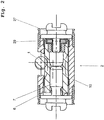
- the expanding lock 2 is described below with reference to Fig.2 explained in more detail.
- the expanding lock 2 is formed by a threaded nut spindle arrangement 8 whose threaded nut 6 is rotatably mounted in a housing 10 of the expanding lock 2 with the aid of an axial bearing 29.
- the spur toothing on the outer surface of the threaded nut 6 is indicated only schematically and standing in engagement with her ringrad 1 shown only in section.
- the electromechanical actuator drives the helical gear 1
- the threaded nut 6, as already described is set in rotation.
- the spindle 7 performs a translational movement in the drawing to the left and presses the first brake shoe 3 against the brake drum 5.
- the electromechanical actuator 15 is mounted tangentially to the brake drum 5 on a mudguard 9, which in turn is fixedly connected to the wheel carrier, not shown.
- This arrangement of the electromechanical actuator 15 is also advantageous in terms of limited space conditions on the wheel.
- the electromechanical actuator 15 drives a gear 11 via a reduction gear 22, whereby the expanding lock 2 is actuated and the two brake shoes 3, 4 are brought into engagement with the inside of the brake drum 5.
- the expansion lock 2 is in turn formed from a threaded nut spindle arrangement 18, as shown in particular in FIG Figure 4 is shown.
- the threaded nut 16 has on its outer surface a spur toothing and forms with the gear 11 a spur gear spur gear.
- the reduction gear 22 or the threaded nut spindle assembly 18 be designed to be self-locking, so that the set clamping force after switching off the electromechanical actuator 15 is maintained.
- the electromechanical actuator 15 with the brake shoes 3, 4, the support device 14 and the mudguard 9 form a preassembled module, which can be particularly easily mounted in the manufacture of motor vehicles.
- both described embodiments of the parking brake according to the invention can be combined with a hydraulic disc brake for service braking by the brake drum 5 arranged in the central region of a brake disc.
- This has the advantage that the parking brake according to the invention operated with a particularly cost-effective control of the electromechanical actuator 15 and the power requirement can be minimized to the electromechanical actuator 15.
Landscapes
- Engineering & Computer Science (AREA)
- General Engineering & Computer Science (AREA)
- Mechanical Engineering (AREA)
- Braking Arrangements (AREA)
Claims (8)
- Frein de stationnement à commande électromécanique pour véhicules automobiles, réalisé sous la forme d'un frein à tambour, comprenant un tambour de frein (5) et une serrure à écartement supportée de manière flottante, pouvant être actionnée par un actionneur électromécanique (15) avec un démultiplicateur (12, 22), laquelle serrure agit sur deux mâchoires de frein (3, 4), la serrure à écartement (2) étant formée par un agencement à broche et écrou fileté (8, 18) dont l'écrou fileté (6, 16) est entraîné par l'actionneur électromécanique (15), caractérisé en ce que le démultiplicateur (12, 22) ou l'agencement à broche et écrou fileté (8, 18) est réalisé de manière autobloquante afin de permettre dans l'état non parcouru par un courant une opération de serrage du frein, en ce que le frein à tambour présente en outre un dispositif de support (14) supporté de manière flottante qui est prévu à l'opposé de la serrure à écartement (2), et le tambour de frein (5) étant disposé dans la région centrale d'un disque de frein.
- Frein de stationnement à commande électromécanique selon la revendication 1, caractérisé en ce que l'écrou fileté (6) présente une denture droite qui forme avec une roue hypoïde (1) entraînée par l'actionneur électromécanique (15) une transmission à roue hypoïde.
- Frein de stationnement à commande électromécanique selon la revendication 1, caractérisé en ce que l'écrou fileté (16) présente une denture droite qui forme avec une roue dentée (11) entraînée par l'actionneur électromécanique (15) une transmission à pignons droits.
- Frein de stationnement à commande électromécanique selon la revendication 1 ou 2, caractérisé en ce que l'actionneur électromécanique (15) est monté radialement par rapport au tambour de frein (5) suivant un angle adapté à l'espace de construction prévu, par rapport à un plan qui est perpendiculaire à l'axe du tambour de frein (5).
- Frein de stationnement à commande électromécanique selon la revendication 1 ou 3, caractérisé en ce que l'actionneur électromécanique (15) est monté tangentiellement par rapport au tambour de frein (5) .
- Frein de stationnement à commande électromécanique selon la revendication 2, caractérisé en ce que le démultiplicateur (12) est prévu entre l'actionneur électromécanique (15) et la roue hypodoïde (1).
- Frein de stationnement à commande électromécanique selon la revendication 3, caractérisé en ce que le démultiplicateur (22) est prévu entre l'actionneur électromécanique (15) et la rouer dentée (11).
- Frein de stationnement à commande électromécanique selon l'une quelconque des revendications précédentes, caractérisé en ce que l'actionneur électromécanique (15) est formé par un moteur électrique qui présente un capteur pour détecter la position de son rotor.
Applications Claiming Priority (5)
| Application Number | Priority Date | Filing Date | Title |
|---|---|---|---|
| DE10261095 | 2002-12-20 | ||
| DE10261095 | 2002-12-20 | ||
| DE10343246 | 2003-09-17 | ||
| DE10343246 | 2003-09-17 | ||
| PCT/EP2003/013997 WO2004059189A1 (fr) | 2002-12-20 | 2003-12-10 | Frein de stationnement à commande électromécanique |
Publications (2)
| Publication Number | Publication Date |
|---|---|
| EP1579124A1 EP1579124A1 (fr) | 2005-09-28 |
| EP1579124B1 true EP1579124B1 (fr) | 2018-10-17 |
Family
ID=32683482
Family Applications (1)
| Application Number | Title | Priority Date | Filing Date |
|---|---|---|---|
| EP03789204.9A Expired - Lifetime EP1579124B1 (fr) | 2002-12-20 | 2003-12-10 | Frein de stationnement commande lectrom canique |
Country Status (6)
| Country | Link |
|---|---|
| US (1) | US20060278477A1 (fr) |
| EP (1) | EP1579124B1 (fr) |
| JP (1) | JP4800767B2 (fr) |
| KR (1) | KR20050084449A (fr) |
| BR (1) | BR0307758B1 (fr) |
| WO (1) | WO2004059189A1 (fr) |
Cited By (1)
| Publication number | Priority date | Publication date | Assignee | Title |
|---|---|---|---|---|
| DE102019207671B3 (de) * | 2019-05-24 | 2020-08-20 | Continental Teves Ag & Co. Ohg | Spreizeinrichtung für eine Trommelbremse |
Families Citing this family (34)
| Publication number | Priority date | Publication date | Assignee | Title |
|---|---|---|---|---|
| DE102004049434A1 (de) * | 2004-01-21 | 2005-10-06 | Continental Teves Ag & Co. Ohg | Elektromechanisch betätigbare Feststellbremse |
| DE112006002895B4 (de) * | 2005-10-31 | 2021-12-16 | ZF Active Safety US lnc. | Elektrische Betätigungseinheit für eine Fahrzeugbremsanordnung |
| DE102008013747B4 (de) | 2007-03-16 | 2016-07-07 | Continental Teves Ag & Co. Ohg | Feststellbremse für Kraftfahrzeuge sowie Bremsbacke hierfür |
| EP2198180B1 (fr) | 2007-09-05 | 2014-08-27 | Continental Teves AG & Co. oHG | Frein de stationnement à commande électromécanique pour véhicules automobiles et procédé de commande de celui-ci |
| DE102008050215A1 (de) | 2008-10-02 | 2010-04-08 | Continental Teves Ag & Co. Ohg | Elektromechanisch betätigbare Feststellbremse für Kraftfahrzeuge |
| US9446748B2 (en) * | 2010-04-16 | 2016-09-20 | Gregory A Ward | Portable antilock brake system |
| JP5546491B2 (ja) * | 2011-03-31 | 2014-07-09 | 株式会社アドヴィックス | 電動駐車ブレーキ装置 |
| KR101421948B1 (ko) * | 2012-12-13 | 2014-07-22 | 현대자동차주식회사 | 전동식 파킹브레이크 엑추에이터 구조 |
| FR3013408B1 (fr) * | 2013-11-19 | 2015-12-25 | Chassis Brakes Int Bv | Frein a tambour fonctionnant en mode simplex et/ou en mode duo servo |
| DE102013224922A1 (de) * | 2013-12-04 | 2015-06-11 | Continental Teves Ag & Co. Ohg | Elektromechanisch betätigbare Trommelbremse |
| FR3016014B1 (fr) * | 2013-12-30 | 2017-03-31 | Chassis Brakes Int Bv | Actionneur avec systeme vis-ecrou irreversible, frein a tambour et dispositif de freinage ainsi equipes |
| FR3016016B1 (fr) * | 2013-12-30 | 2016-02-12 | Chassis Brakes Int Bv | Motoreducteur avec moteur electrique adaptable pour actionneur de frein a tambour |
| FR3016015B1 (fr) * | 2013-12-30 | 2017-03-31 | Chassis Brakes Int Bv | Motoreducteur a train epicycloidal et frein a tambour et dispositif de freinage ainsi equipes |
| US9476469B2 (en) | 2014-01-22 | 2016-10-25 | Akebono Brake Industry Co., Ltd | Electric drum or drum-in-hat park brake |
| JP6254697B2 (ja) * | 2014-06-26 | 2017-12-27 | 曙ブレーキ工業株式会社 | ドラムブレーキ装置 |
| KR101532231B1 (ko) * | 2014-07-23 | 2015-07-01 | 현대모비스 주식회사 | 차량용 제동장치 |
| KR20170023319A (ko) * | 2015-08-20 | 2017-03-03 | 현대모비스 주식회사 | 차량용 브레이크 |
| CN105299105A (zh) * | 2015-12-01 | 2016-02-03 | 潍坊埃锐制动系统有限公司 | 用于鼓式制动器的电子驻车制动装置 |
| CN107521489A (zh) * | 2016-06-21 | 2017-12-29 | 香宾 | 一种提高驾驶安全的道路辅助系统汽车 |
| KR101889455B1 (ko) | 2016-10-17 | 2018-09-21 | 현대모비스 주식회사 | 전자식 주차 브레이크 장치 |
| US11060572B2 (en) * | 2017-02-07 | 2021-07-13 | ZF Active Safety US Inc. | Electric actuator assembly for a drum brake assembly |
| DE102017218219A1 (de) * | 2017-10-12 | 2019-04-18 | Continental Teves Ag & Co. Ohg | Spreizeinheit für Trommelbremse mit Verschleißwegnachstellung und die Trommelbremse |
| KR101988517B1 (ko) * | 2018-01-08 | 2019-06-13 | 주식회사 만도 | 차량용 로터리 댐퍼의 감쇠력 보상장치 |
| DE102018102848A1 (de) * | 2018-02-08 | 2019-08-08 | Brose Fahrzeugteile Gmbh & Co. Kommanditgesellschaft, Bamberg | Trommelbremse mit Bremselementen |
| KR20190128346A (ko) * | 2018-05-08 | 2019-11-18 | 주식회사 만도 | 드럼 일체형 파킹 브레이크 |
| FR3091324B1 (fr) * | 2018-12-27 | 2021-01-29 | Foundation Brakes France | Actionneur pour frein electromecanique a detecteur d’etat integre |
| US11339842B2 (en) | 2019-03-26 | 2022-05-24 | Akebono Brake Industry Co., Ltd. | Brake system with torque distributing assembly |
| KR102647979B1 (ko) * | 2019-04-12 | 2024-03-15 | 에이치엘만도 주식회사 | 전자식 주차 브레이크 |
| DE102019206031B4 (de) | 2019-04-26 | 2020-11-19 | Continental Teves Ag & Co. Ohg | Spreizeinrichtung für eine Trommelbremse |
| KR102258686B1 (ko) * | 2019-10-29 | 2021-05-31 | 현대모비스 주식회사 | 전자제어식 브레이크 장치 |
| KR102401766B1 (ko) | 2021-08-11 | 2022-05-25 | 주식회사 만도 | 전자기계식 브레이크 및 이를 구비하는 차량 |
| KR102403441B1 (ko) * | 2021-12-22 | 2022-05-30 | 주식회사 만도 | 전자기계식 드럼 브레이크 |
| US12296799B2 (en) * | 2022-09-16 | 2025-05-13 | ZF Active Safety US Inc. | Actuator for drum brake assembly |
| DE102023208048A1 (de) | 2023-08-23 | 2025-02-27 | Robert Bosch Gesellschaft mit beschränkter Haftung | Elektromechanische Trommelbremse |
Citations (2)
| Publication number | Priority date | Publication date | Assignee | Title |
|---|---|---|---|---|
| US4793447A (en) * | 1986-12-23 | 1988-12-27 | Allied-Signal Inc. | Electrically operated disc brake |
| US6209689B1 (en) * | 1997-11-22 | 2001-04-03 | Continental Teves Ag & Co., Ohg | Method and system for actuating an electromechanically operable parking brake for automotive vehicles |
Family Cites Families (9)
| Publication number | Priority date | Publication date | Assignee | Title |
|---|---|---|---|---|
| US3809191A (en) * | 1969-08-04 | 1974-05-07 | Index Ind Inc | Auxiliary braking system |
| US4928543A (en) * | 1988-04-19 | 1990-05-29 | Allied-Signal Inc. | Electrically operated drum brake |
| JP3726443B2 (ja) * | 1997-09-29 | 2005-12-14 | トヨタ自動車株式会社 | 電動ブレーキ装置 |
| JP2000297833A (ja) * | 1999-04-15 | 2000-10-24 | Akebono Brake Ind Co Ltd | 電動式パーキングブレーキ |
| JP4335375B2 (ja) * | 1999-09-10 | 2009-09-30 | 豊生ブレーキ工業株式会社 | モータ駆動ドラムブレーキ用アクチュエータ |
| NL1013783C2 (nl) * | 1999-12-07 | 2001-06-08 | Skf Eng & Res Centre Bv | Trommelrem en elektrische actuator daarvoor. |
| JP2001173693A (ja) * | 1999-12-21 | 2001-06-26 | Hosei Brake Ind Ltd | モータ駆動ブレーキ用アクチュエータ |
| JP2001254770A (ja) * | 2000-03-13 | 2001-09-21 | Akebono Brake Ind Co Ltd | ドラムブレーキ装置におけるパーキング機構 |
| ITTO20011137A1 (it) * | 2001-12-07 | 2003-06-09 | Skf Ind Spa | Attuatore a doppia vite. |
-
2003
- 2003-12-10 WO PCT/EP2003/013997 patent/WO2004059189A1/fr not_active Ceased
- 2003-12-10 US US10/540,165 patent/US20060278477A1/en not_active Abandoned
- 2003-12-10 BR BRPI0307758-6A patent/BR0307758B1/pt not_active IP Right Cessation
- 2003-12-10 EP EP03789204.9A patent/EP1579124B1/fr not_active Expired - Lifetime
- 2003-12-10 JP JP2005509697A patent/JP4800767B2/ja not_active Expired - Fee Related
- 2003-12-10 KR KR1020057011640A patent/KR20050084449A/ko not_active Ceased
Patent Citations (2)
| Publication number | Priority date | Publication date | Assignee | Title |
|---|---|---|---|---|
| US4793447A (en) * | 1986-12-23 | 1988-12-27 | Allied-Signal Inc. | Electrically operated disc brake |
| US6209689B1 (en) * | 1997-11-22 | 2001-04-03 | Continental Teves Ag & Co., Ohg | Method and system for actuating an electromechanically operable parking brake for automotive vehicles |
Cited By (1)
| Publication number | Priority date | Publication date | Assignee | Title |
|---|---|---|---|---|
| DE102019207671B3 (de) * | 2019-05-24 | 2020-08-20 | Continental Teves Ag & Co. Ohg | Spreizeinrichtung für eine Trommelbremse |
Also Published As
| Publication number | Publication date |
|---|---|
| JP2006511773A (ja) | 2006-04-06 |
| US20060278477A1 (en) | 2006-12-14 |
| JP4800767B2 (ja) | 2011-10-26 |
| KR20050084449A (ko) | 2005-08-26 |
| EP1579124A1 (fr) | 2005-09-28 |
| WO2004059189A1 (fr) | 2004-07-15 |
| BR0307758A (pt) | 2004-12-21 |
| BR0307758B1 (pt) | 2014-08-19 |
Similar Documents
| Publication | Publication Date | Title |
|---|---|---|
| EP1579124B1 (fr) | Frein de stationnement commande lectrom canique | |
| EP1025372B1 (fr) | Systeme de freinage pour vehicule routier | |
| DE10102685B4 (de) | Betätigungsmechanismus mit Kraftsensor für eine Bremse | |
| DE10112570B4 (de) | Elektrisch betätigbare Scheibenbremse | |
| EP1692413B1 (fr) | Frein electromecanique a autorenforcement | |
| EP2812595B1 (fr) | Système de retenue de garniture d'un frein à disque d'un véhicule à moteur | |
| EP1706298B1 (fr) | Frein de stationnement active de maniere electromecanique | |
| DE112012001273T5 (de) | Elektrische Bremse mit Parkmechanismus | |
| DE19621533A1 (de) | Elektromotorische Bremsvorrichtung | |
| WO2011113554A2 (fr) | Frein à disque et procédé de fabrication d'un frein à disque | |
| DE102012217275A1 (de) | Scheibenbremsvorrichtung | |
| EP1664573B1 (fr) | Frein azimutal pour eoliennes | |
| DE102011086152B4 (de) | Bremseinrichtung | |
| EP3077694A2 (fr) | Module de frein à tambour entraînable par moteur électrique | |
| EP3487735B1 (fr) | Frein de service d'un véhicule avec assistance electroméchanique et hydraulique | |
| DE102006012440A1 (de) | Bremse mit Spindel und Kurvenscheiben-Anordnung | |
| DE10317949B4 (de) | Elektrisch betätigte Bremsanordnung für ein Getriebe | |
| DE102021129954A1 (de) | Trägerbaugruppe und Antriebsbaugruppe für eine Aktorbaugruppe für eine Fahrzeugbremse sowie Aktorbaugruppe | |
| EP1307666A1 (fr) | Frein a disque | |
| DE102007054498A1 (de) | Elektromechanisch betätigbare Feststellbremse | |
| EP2467611B1 (fr) | Dispositif d'arrêt de rotation à effet radial | |
| DE102021212784B3 (de) | Kombinierte Radbremse eines Fahrzeugs einschließlich Vorrichtung zur Betätigung von Betriebsbremse und Feststellbremse | |
| DE69102746T2 (de) | Elektromechanische Steuerung mit Hilfe einer Zentrifuge. | |
| DE10227828B4 (de) | Elektrisch betätigbare Kraftfahrzeug-Scheibenbremse | |
| EP2002141B1 (fr) | Frein à disque à auto-amplification et procédé de commande de celui-ci |
Legal Events
| Date | Code | Title | Description |
|---|---|---|---|
| PUAI | Public reference made under article 153(3) epc to a published international application that has entered the european phase |
Free format text: ORIGINAL CODE: 0009012 |
|
| 17P | Request for examination filed |
Effective date: 20050720 |
|
| AK | Designated contracting states |
Kind code of ref document: A1 Designated state(s): AT BE BG CH CY CZ DE DK EE ES FI FR GB GR HU IE IT LI LU MC NL PT RO SE SI SK TR |
|
| AX | Request for extension of the european patent |
Extension state: AL LT LV MK |
|
| DAX | Request for extension of the european patent (deleted) | ||
| RBV | Designated contracting states (corrected) |
Designated state(s): CZ DE ES FR GB IT |
|
| 17Q | First examination report despatched |
Effective date: 20100615 |
|
| REG | Reference to a national code |
Ref country code: DE Ref legal event code: R079 Ref document number: 50315793 Country of ref document: DE Free format text: PREVIOUS MAIN CLASS: F16D0065270000 Ipc: F16D0065140000 |
|
| GRAP | Despatch of communication of intention to grant a patent |
Free format text: ORIGINAL CODE: EPIDOSNIGR1 |
|
| RIC1 | Information provided on ipc code assigned before grant |
Ipc: F16D 125/52 20120101ALN20180514BHEP Ipc: F16D 65/14 19680901AFI20180514BHEP Ipc: F16D 121/24 20120101ALN20180514BHEP Ipc: F16D 65/22 19680901ALI20180514BHEP Ipc: F16D 125/48 20120101ALN20180514BHEP Ipc: F16D 51/50 19680901ALI20180514BHEP Ipc: F16D 125/40 20120101ALN20180514BHEP |
|
| INTG | Intention to grant announced |
Effective date: 20180615 |
|
| GRAS | Grant fee paid |
Free format text: ORIGINAL CODE: EPIDOSNIGR3 |
|
| GRAA | (expected) grant |
Free format text: ORIGINAL CODE: 0009210 |
|
| RAP1 | Party data changed (applicant data changed or rights of an application transferred) |
Owner name: CONTINENTAL TEVES AG & CO. OHG |
|
| RIN1 | Information on inventor provided before grant (corrected) |
Inventor name: SALZMANN, SEBASTIAN Inventor name: WEILER, ROLF Inventor name: SCHMITT, STEFAN, JOHANNES Inventor name: BALZ, JUERGEN Inventor name: KAISER, ANDREAS |
|
| AK | Designated contracting states |
Kind code of ref document: B1 Designated state(s): CZ DE ES FR GB IT |
|
| REG | Reference to a national code |
Ref country code: GB Ref legal event code: FG4D Free format text: NOT ENGLISH |
|
| REG | Reference to a national code |
Ref country code: DE Ref legal event code: R096 Ref document number: 50315793 Country of ref document: DE |
|
| RIC2 | Information provided on ipc code assigned after grant |
Ipc: F16D 125/40 20120101ALN20180514BHEP Ipc: F16D 51/50 20060101ALI20180514BHEP Ipc: F16D 125/48 20120101ALN20180514BHEP Ipc: F16D 121/24 20120101ALN20180514BHEP Ipc: F16D 65/14 20060101AFI20180514BHEP Ipc: F16D 65/22 20060101ALI20180514BHEP Ipc: F16D 125/52 20120101ALN20180514BHEP |
|
| PG25 | Lapsed in a contracting state [announced via postgrant information from national office to epo] |
Ref country code: ES Free format text: LAPSE BECAUSE OF FAILURE TO SUBMIT A TRANSLATION OF THE DESCRIPTION OR TO PAY THE FEE WITHIN THE PRESCRIBED TIME-LIMIT Effective date: 20181017 |
|
| REG | Reference to a national code |
Ref country code: DE Ref legal event code: R097 Ref document number: 50315793 Country of ref document: DE |
|
| PG25 | Lapsed in a contracting state [announced via postgrant information from national office to epo] |
Ref country code: CZ Free format text: LAPSE BECAUSE OF FAILURE TO SUBMIT A TRANSLATION OF THE DESCRIPTION OR TO PAY THE FEE WITHIN THE PRESCRIBED TIME-LIMIT Effective date: 20181017 Ref country code: IT Free format text: LAPSE BECAUSE OF FAILURE TO SUBMIT A TRANSLATION OF THE DESCRIPTION OR TO PAY THE FEE WITHIN THE PRESCRIBED TIME-LIMIT Effective date: 20181017 |
|
| PLBE | No opposition filed within time limit |
Free format text: ORIGINAL CODE: 0009261 |
|
| STAA | Information on the status of an ep patent application or granted ep patent |
Free format text: STATUS: NO OPPOSITION FILED WITHIN TIME LIMIT |
|
| 26N | No opposition filed |
Effective date: 20190718 |
|
| GBPC | Gb: european patent ceased through non-payment of renewal fee |
Effective date: 20190117 |
|
| PG25 | Lapsed in a contracting state [announced via postgrant information from national office to epo] |
Ref country code: FR Free format text: LAPSE BECAUSE OF NON-PAYMENT OF DUE FEES Effective date: 20181217 |
|
| PG25 | Lapsed in a contracting state [announced via postgrant information from national office to epo] |
Ref country code: GB Free format text: LAPSE BECAUSE OF NON-PAYMENT OF DUE FEES Effective date: 20190117 |
|
| PGFP | Annual fee paid to national office [announced via postgrant information from national office to epo] |
Ref country code: DE Payment date: 20191231 Year of fee payment: 17 |
|
| REG | Reference to a national code |
Ref country code: DE Ref legal event code: R119 Ref document number: 50315793 Country of ref document: DE |
|
| PG25 | Lapsed in a contracting state [announced via postgrant information from national office to epo] |
Ref country code: DE Free format text: LAPSE BECAUSE OF NON-PAYMENT OF DUE FEES Effective date: 20210701 |