EP1578587B1 - Molding apparatus with mold blocks having profiled face adjustment - Google Patents
Molding apparatus with mold blocks having profiled face adjustment Download PDFInfo
- Publication number
- EP1578587B1 EP1578587B1 EP03770831.0A EP03770831A EP1578587B1 EP 1578587 B1 EP1578587 B1 EP 1578587B1 EP 03770831 A EP03770831 A EP 03770831A EP 1578587 B1 EP1578587 B1 EP 1578587B1
- Authority
- EP
- European Patent Office
- Prior art keywords
- pipe
- mold
- mold blocks
- face
- wall
- Prior art date
- Legal status (The legal status is an assumption and is not a legal conclusion. Google has not performed a legal analysis and makes no representation as to the accuracy of the status listed.)
- Expired - Lifetime
Links
- 238000000465 moulding Methods 0.000 title claims description 33
- 238000001816 cooling Methods 0.000 claims description 20
- 239000004033 plastic Substances 0.000 claims description 17
- 230000015572 biosynthetic process Effects 0.000 description 1
- 238000000071 blow moulding Methods 0.000 description 1
- 230000003247 decreasing effect Effects 0.000 description 1
- 238000004519 manufacturing process Methods 0.000 description 1
- 238000000034 method Methods 0.000 description 1
- 229920001169 thermoplastic Polymers 0.000 description 1
- 239000004416 thermosoftening plastic Substances 0.000 description 1
Images

Classifications
-
- B—PERFORMING OPERATIONS; TRANSPORTING
- B29—WORKING OF PLASTICS; WORKING OF SUBSTANCES IN A PLASTIC STATE IN GENERAL
- B29C—SHAPING OR JOINING OF PLASTICS; SHAPING OF MATERIAL IN A PLASTIC STATE, NOT OTHERWISE PROVIDED FOR; AFTER-TREATMENT OF THE SHAPED PRODUCTS, e.g. REPAIRING
- B29C33/00—Moulds or cores; Details thereof or accessories therefor
- B29C33/30—Mounting, exchanging or centering
- B29C33/306—Exchangeable mould parts, e.g. cassette moulds, mould inserts
-
- B—PERFORMING OPERATIONS; TRANSPORTING
- B29—WORKING OF PLASTICS; WORKING OF SUBSTANCES IN A PLASTIC STATE IN GENERAL
- B29C—SHAPING OR JOINING OF PLASTICS; SHAPING OF MATERIAL IN A PLASTIC STATE, NOT OTHERWISE PROVIDED FOR; AFTER-TREATMENT OF THE SHAPED PRODUCTS, e.g. REPAIRING
- B29C33/00—Moulds or cores; Details thereof or accessories therefor
- B29C33/34—Moulds or cores; Details thereof or accessories therefor movable, e.g. to or from the moulding station
- B29C33/36—Moulds or cores; Details thereof or accessories therefor movable, e.g. to or from the moulding station continuously movable in one direction, e.g. in a closed circuit
-
- B—PERFORMING OPERATIONS; TRANSPORTING
- B29—WORKING OF PLASTICS; WORKING OF SUBSTANCES IN A PLASTIC STATE IN GENERAL
- B29C—SHAPING OR JOINING OF PLASTICS; SHAPING OF MATERIAL IN A PLASTIC STATE, NOT OTHERWISE PROVIDED FOR; AFTER-TREATMENT OF THE SHAPED PRODUCTS, e.g. REPAIRING
- B29C48/00—Extrusion moulding, i.e. expressing the moulding material through a die or nozzle which imparts the desired form; Apparatus therefor
- B29C48/03—Extrusion moulding, i.e. expressing the moulding material through a die or nozzle which imparts the desired form; Apparatus therefor characterised by the shape of the extruded material at extrusion
- B29C48/09—Articles with cross-sections having partially or fully enclosed cavities, e.g. pipes or channels
-
- B—PERFORMING OPERATIONS; TRANSPORTING
- B29—WORKING OF PLASTICS; WORKING OF SUBSTANCES IN A PLASTIC STATE IN GENERAL
- B29C—SHAPING OR JOINING OF PLASTICS; SHAPING OF MATERIAL IN A PLASTIC STATE, NOT OTHERWISE PROVIDED FOR; AFTER-TREATMENT OF THE SHAPED PRODUCTS, e.g. REPAIRING
- B29C48/00—Extrusion moulding, i.e. expressing the moulding material through a die or nozzle which imparts the desired form; Apparatus therefor
- B29C48/03—Extrusion moulding, i.e. expressing the moulding material through a die or nozzle which imparts the desired form; Apparatus therefor characterised by the shape of the extruded material at extrusion
- B29C48/13—Articles with a cross-section varying in the longitudinal direction, e.g. corrugated pipes
-
- B—PERFORMING OPERATIONS; TRANSPORTING
- B29—WORKING OF PLASTICS; WORKING OF SUBSTANCES IN A PLASTIC STATE IN GENERAL
- B29C—SHAPING OR JOINING OF PLASTICS; SHAPING OF MATERIAL IN A PLASTIC STATE, NOT OTHERWISE PROVIDED FOR; AFTER-TREATMENT OF THE SHAPED PRODUCTS, e.g. REPAIRING
- B29C48/00—Extrusion moulding, i.e. expressing the moulding material through a die or nozzle which imparts the desired form; Apparatus therefor
- B29C48/25—Component parts, details or accessories; Auxiliary operations
- B29C48/252—Drive or actuation means; Transmission means; Screw supporting means
- B29C48/2528—Drive or actuation means for non-plasticising purposes, e.g. dosing unit
-
- B—PERFORMING OPERATIONS; TRANSPORTING
- B29—WORKING OF PLASTICS; WORKING OF SUBSTANCES IN A PLASTIC STATE IN GENERAL
- B29C—SHAPING OR JOINING OF PLASTICS; SHAPING OF MATERIAL IN A PLASTIC STATE, NOT OTHERWISE PROVIDED FOR; AFTER-TREATMENT OF THE SHAPED PRODUCTS, e.g. REPAIRING
- B29C48/00—Extrusion moulding, i.e. expressing the moulding material through a die or nozzle which imparts the desired form; Apparatus therefor
- B29C48/25—Component parts, details or accessories; Auxiliary operations
- B29C48/256—Exchangeable extruder parts
- B29C48/2566—Die parts
-
- B—PERFORMING OPERATIONS; TRANSPORTING
- B29—WORKING OF PLASTICS; WORKING OF SUBSTANCES IN A PLASTIC STATE IN GENERAL
- B29C—SHAPING OR JOINING OF PLASTICS; SHAPING OF MATERIAL IN A PLASTIC STATE, NOT OTHERWISE PROVIDED FOR; AFTER-TREATMENT OF THE SHAPED PRODUCTS, e.g. REPAIRING
- B29C48/00—Extrusion moulding, i.e. expressing the moulding material through a die or nozzle which imparts the desired form; Apparatus therefor
- B29C48/25—Component parts, details or accessories; Auxiliary operations
- B29C48/30—Extrusion nozzles or dies
- B29C48/3001—Extrusion nozzles or dies characterised by the material or their manufacturing process
-
- B—PERFORMING OPERATIONS; TRANSPORTING
- B29—WORKING OF PLASTICS; WORKING OF SUBSTANCES IN A PLASTIC STATE IN GENERAL
- B29C—SHAPING OR JOINING OF PLASTICS; SHAPING OF MATERIAL IN A PLASTIC STATE, NOT OTHERWISE PROVIDED FOR; AFTER-TREATMENT OF THE SHAPED PRODUCTS, e.g. REPAIRING
- B29C48/00—Extrusion moulding, i.e. expressing the moulding material through a die or nozzle which imparts the desired form; Apparatus therefor
- B29C48/25—Component parts, details or accessories; Auxiliary operations
- B29C48/30—Extrusion nozzles or dies
- B29C48/303—Extrusion nozzles or dies using dies or die parts movable in a closed circuit, e.g. mounted on movable endless support
-
- B—PERFORMING OPERATIONS; TRANSPORTING
- B29—WORKING OF PLASTICS; WORKING OF SUBSTANCES IN A PLASTIC STATE IN GENERAL
- B29C—SHAPING OR JOINING OF PLASTICS; SHAPING OF MATERIAL IN A PLASTIC STATE, NOT OTHERWISE PROVIDED FOR; AFTER-TREATMENT OF THE SHAPED PRODUCTS, e.g. REPAIRING
- B29C49/00—Blow-moulding, i.e. blowing a preform or parison to a desired shape within a mould; Apparatus therefor
- B29C49/0015—Making articles of indefinite length, e.g. corrugated tubes
- B29C49/0021—Making articles of indefinite length, e.g. corrugated tubes using moulds or mould parts movable in a closed path, e.g. mounted on movable endless supports
Definitions
- the present invention relates to a pipe molding system including a mold tunnel formed by moving mold blocks in which the shape of the pipe can be varied without having to replace the mold blocks.
- DE 200 09 930 U1 discloses a section of a molding block for a moving form tunnel comprising crests and troughs that form a profiled surface for manufacturing a plastic pipe that has an outer surface corresponding to the mold's surface, wherein the mold's surface is provided with means for modifying the profile in order to change the profile of the mold; according to the preamble of claim 1.
- the present invention provides a molding system which is able to provide changes to the shape of an extruded pipe without having to replace the entire mold block sections in the molding system.
- the present invention provides a pipe molding system which makes a continuous length of plastic pipe with the system including mold block sections having profiled faces which are reconfigurable in their face profile to provide pipe shape variances without having to replace the entire mold blocks, according to the characterising part of claim 1.
- the molding system includes a plurality of mold blocks which move along the molding path to form double wall plastic pipe having an outer wall with corrugations which set outside diameter of the pipe and an inner wall around a bore through the pipe.
- the sections of the mold blocks have profiled faces which determine shape of the pipe and those profiled faces are reconfigurable in profile between a first and a second face profile to vary both depth of the corrugations and diameter of the bore through the pipe. This is done without varying external diameter of the pipe while maintaining essentially constant thickness of the pipe walls.
- a single molding system without the requirement for mold block replacement can be used to make either a stronger i.e., more rigid pipe or a softer i.e., more flexible pipe.
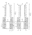
- FIG. 1 shows a pipe molding apparatus generally indicated at 1.
- This pipe molding apparatus includes an extruder 3 which provides molten plastic through plastic flow channels of an extruder die 5 to a moving mold tunnel generally indicated at 7.
- the moving mold tunnel is formed by a plurality of mold block sections 9 to each side of the mold tunnel.
- These mold block sections have profiled i.e., corrugated faces to receive plastic from the two channel mouths 6a and 6b of the die equipment located within the mold tunnel.
- the plastic emanating from channel mouth 6a flows into the troughs in the faces of the mold blocks to form an outer corrugated wall of the pipe.
- the plastic emanating through channel mouth 6b forms an inner pipe wall bordering a central bore through the pipe.
- the molten plastic of the inner pipe wall is set to shape and cooled by a cooling plug 11 internally of the mold tunnel.
- Figure 2 of the drawings shows the apparatus set up to produce a double wall pipe 18 having an inner pipe wall 19 and an outer corrugated pipe wall 21.
- Each of the mold blocks 9 includes a trough 13 to shape the corrugations 21 on pipe 18. These corrugations set the outside diameter of the pipe.
- Each of the mold blocks further includes a mold block crest between each of the troughs 13.
- the height of this mold block crest is variable to vary the depth of the corrugations. This variance in turn produces a bore diameter change in the pipe with little or no change to the wall thicknesses of the pipe.
- each of the mold block sections 9 has a mounting surface 12 on each side of each of the troughs 13 in the mold block section.
- This mounting surface 12 is adapted to interchangeably receive different mold block crest forming attachments.
- crest forming attachments 15 are mounted to each of the mold block mounting surfaces 12.
- FIG. 3 it will be seen that the mold block sections 9 and in particular the profiled faces of the mold block sections have been reconfigured from the Figure 2 face profile to a different face profile. This is done by the attachment of crest forming attachments 23 to the mounting surfaces 12 of the mold block sections in the Figure 3 set up. Crest forming attachments 23 of Figure 3 are substantially longer than crest forming attachments 15 of the Figure 2 set up. Furthermore as will be seen in Figure 3 of the drawings the pipe generally indicated at 27 formed using the Figure 3 set up includes an outer wall formed by corrugations 31 which are substantially taller than the corrugations 21 of pipe 18 from Figure 2 .
- the bore diameter of the pipe 27 defined by the inner pipe wall 29 is substantially smaller than the bore diameter through pipe 18 defined by inner wall 19 in Figure 2 . Accordingly, pipe 27 of Figure 3 is a substantially stronger or more rigid pipe than pipe 18 of Figure 2 . However, the overall external diameter of the two pipes is identical. Furthermore, the wall thickness of pipe 18 is essentially the same as the wall thickness of pipe 29.
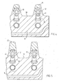
- Figures 4 and 5 of the drawings show a number of preferred features of the present invention.
- Figure 4 shows a mold block section 9 provided with the shorter crest forming members15 supported by the mounting surfaces 12 to either side of the troughs 13 in the face of the mold block sections.
- Figure 5 shows the taller crest forming members 23 fitted to the mounting surfaces 12 to either side of the trough 13 in the profiled face of mold block section 9.
- Figures 4 and 5 of the drawings show that the mold block sections include sophisticated vacuum and cooling channels required to first shape and then cool the plastic at the faces of the mold blocks.
- the interchangeability of the face attachments at the mounting surfaces 12 of the mold block sections in no way impedes or affects either the vacuum or the cooling channels.
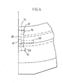
- Figures 4, 5 and 6 also show a particular means of replaceably mounting the face attachments to the mold block sections.
- This means comprises a bracket 35 having forwardly extending arms 37 and 39 to opposite ends of the bracket.
- the mounting surface of the mold block section is provided away from the pipe forming region with a bore 40 to receive a threaded bolt 41.
- Also provided in the mold block section is a recess 10 for receiving the arm 39 of bracket 35.
- a similar recess 16 is provided in the face attachment 15 to receive the arm 37 of bracket 35.
- bracket is easily secured to and removed from the mold block to secure face attachment 15 or to replace it with face attachment 23 which has a corresponding bracket receiving recess.
- a pipe molding system which makes a continuous length of plastic pipe, said system comprising first and second mold block sections which circulate to and away from a mold tunnel into which a continuous stream of molten plastic is fed to form the pipe with an inner bore surrounded by a wall having an undulating exterior surface, the first mold block sections closing with the second mold block sections to form a moving line of closed mold blocks while circulating through the mold tunnel and the first and second mold block sections parting from one another while circulating away from and back to the mold tunnel, both said first and second mold block sections having profiled faces which dictate shape of the pipe, said profiled faces including face attachments which are interchangeable at the profiled faces with other face attachments of different configurations to vary the shape of the pipe without replacing the mold block sections.
- the pipe molding system is used to form the pipe with a smooth wall at the inner bore of the pipe and with a corrugated outer surface, the faces of the mold block sections having alternating crests and troughs on the profiled faces thereof, the face attachments comprising first attachments of a first length and second attachments of a second length, the first and second attachments being interchangeably fittable at the profiled faces of the mold block sections to vary height of the crests according to which one of said first and second attachments is fitted at the profiled faces which in turn produces a variance of depth of the troughs of the profiled faces of the mold block sections.
- the pipe molding apparatus includes a locking member which releaseably locks each face attachment at each of the profiled faces of the mold block sections.
- a pipe molding apparatus for making a continuous length of plastic pipe, said apparatus comprising first and second mold block sections each having profiled faces formed by crests and troughs on the profiled faces of the mold block sections, a first set of face attachments and a second set of face attachments, the first and second sets of face attachments being interchangeably and releasbly fittable to the profiled faces of the mold block sections, and first and second cooling plugs of diameters differing from one another, the first and second mold block sections circulating to and away from a molding tunnel of the apparatus which contains one of said cooling plugs, the mold tunnel receiving a continuous stream of molten plastic to form the pipe over the one of the cooling plugs with an internal bore and a wall having an undulating exterior surface around said bore, the undulating surface defining external diameter of the pipe, the first mold block sections closing with the second mold block sections to form a moving line of closed mold blocks while circulating through the mold tunnel and the first and second mold block sections parting from one another while circulating away
- said first set and second set of face attachments interchangeably and releasably secure as crest forming members the of the profiled faces of the first and second mold block sections, the face attachments of the first set of face attachments being of a first length which is less than length of the face attachments of the second set of face attachments and the first cooling plug having a diameter greater than that of the second cooling plug and the second bore diameter of the pipe being less than the first bore diameter of the pipe.
Landscapes
- Engineering & Computer Science (AREA)
- Mechanical Engineering (AREA)
- Manufacturing & Machinery (AREA)
- Extrusion Moulding Of Plastics Or The Like (AREA)
- Moulds For Moulding Plastics Or The Like (AREA)
- Shaping Of Tube Ends By Bending Or Straightening (AREA)
Applications Claiming Priority (3)
| Application Number | Priority Date | Filing Date | Title |
|---|---|---|---|
| CA2411881 | 2002-11-15 | ||
| CA002411881A CA2411881C (en) | 2002-11-15 | 2002-11-15 | Molding apparatus with mold blocks having face adjustment |
| PCT/CA2003/001719 WO2004045828A1 (en) | 2002-11-15 | 2003-11-12 | Molding apparatus with mold blocks having profiled face adjustment |
Publications (2)
| Publication Number | Publication Date |
|---|---|
| EP1578587A1 EP1578587A1 (en) | 2005-09-28 |
| EP1578587B1 true EP1578587B1 (en) | 2014-06-18 |
Family
ID=32315153
Family Applications (1)
| Application Number | Title | Priority Date | Filing Date |
|---|---|---|---|
| EP03770831.0A Expired - Lifetime EP1578587B1 (en) | 2002-11-15 | 2003-11-12 | Molding apparatus with mold blocks having profiled face adjustment |
Country Status (13)
Families Citing this family (9)
| Publication number | Priority date | Publication date | Assignee | Title |
|---|---|---|---|---|
| DE10148294C1 (de) * | 2001-09-29 | 2003-01-16 | Unicor Rohrsysteme Gmbh | Formbackenhälfte für einen Corrugator zum Herstellen von Querrippenrohren |
| CA2607517C (en) * | 2007-10-22 | 2012-01-31 | Manfred A. A. Lupke | Pipe extruding system with cooling plug separation |
| JP5609423B2 (ja) * | 2009-09-30 | 2014-10-22 | キョーラク株式会社 | 空調ダクトの製造方法、及び空調ダクト |
| CN105216287A (zh) * | 2015-10-16 | 2016-01-06 | 苏州杰威尔精密机械有限公司 | 波纹管成型模块 |
| DE102015014133A1 (de) * | 2015-10-31 | 2017-05-04 | Kocher-Plastik Maschinenbau Gmbh | Formwerkzeug |
| DE102018217798A1 (de) * | 2018-10-17 | 2020-04-23 | Fränkische Industrial Pipes GmbH & Co. KG | Variable Formbacke |
| CN112477214B (zh) * | 2020-11-11 | 2022-05-17 | 四川文诚管业有限公司 | 一种波纹管生产线的成型装置 |
| CN114211669B (zh) * | 2021-12-21 | 2024-05-31 | 郑州轻工业大学 | 一种可重构软体驱动器制作模具及其制作驱动器的方法 |
| CN114801106B (zh) * | 2022-04-27 | 2024-05-17 | 大连天薇管业有限公司 | 一种双壁波纹管生产设备及生产方法 |
Family Cites Families (17)
| Publication number | Priority date | Publication date | Assignee | Title |
|---|---|---|---|---|
| US3286305A (en) * | 1964-09-03 | 1966-11-22 | Rexall Drug Chemical | Apparatus for continuous manufacture of hollow articles |
| US3380121A (en) | 1965-07-30 | 1968-04-30 | American Can Co | Mold with replaceable inserts |
| US3430292A (en) * | 1967-04-28 | 1969-03-04 | Acme Hamilton Mfg Corp | Apparatus for the continuous formation of tubular articles |
| US3784346A (en) * | 1972-06-12 | 1974-01-08 | Plastic Tubing | Converted corrugated pipe molding machine |
| CA1083766A (en) * | 1977-02-07 | 1980-08-19 | Gerd P.H. Lupke | Apparatus for producing thermoplastic tubing |
| JPS5446265A (en) * | 1977-09-20 | 1979-04-12 | Furukawa Electric Co Ltd:The | Mandrel for molding plastic spiral corrugated pipe |
| DE3120480A1 (de) * | 1981-05-22 | 1982-12-09 | Hegler, Wilhelm, 8730 Bad Kissingen | Vorrichtung zur herstellung von kunststoffrohren mit querrillen |
| JPH02125715A (ja) * | 1988-11-04 | 1990-05-14 | Mirai Ind Co Ltd | 長尺樹脂成形品の押出成形装置における金型の冷却構造 |
| WO1992022416A1 (en) * | 1991-06-14 | 1992-12-23 | Lupke Manfred Arno Alfred | Travelling mold tunnel apparatus for smooth walled pipe |
| DE4340291A1 (de) * | 1993-11-26 | 1995-06-01 | Krupp Corpoplast Masch | Mehrfachnutzung von Blasluft |
| US5582849A (en) * | 1994-05-06 | 1996-12-10 | Lupke; Manfred A. A. | Travelling mold with mold block carriers |
| CA2231624C (en) * | 1998-03-09 | 2001-02-06 | Manfred A. A. Lupke | Pipe molding apparatus with air float of plastic onto tapered cooling plug |
| DE19922726A1 (de) * | 1999-05-18 | 2000-11-23 | Ralph Peter Hegler | Vorrichtung zur Herstellung von Kunststoff-Wellrohren |
| DE20000903U1 (de) * | 2000-01-20 | 2000-03-09 | RK Rose + Krieger GmbH & Co. KG Verbindungs- und Positioniersysteme, 32423 Minden | An einem Rohr befestigter Halter für ein plattenförmiges Bauteil |
| DE20009030U1 (de) * | 2000-02-23 | 2000-08-24 | Lupke, Manfred Arno Alfred, Thornhill, Ontario | Formblockabschnitt mit einstellbarer Formfläche |
| DE20009930U1 (de) | 2000-06-02 | 2000-09-21 | Behncke Solar- und Wärmetechnik GmbH, 63906 Erlenbach | Einteilige Haltevorrichtung für Wärmetauschermatten |
| DE10148294C1 (de) * | 2001-09-29 | 2003-01-16 | Unicor Rohrsysteme Gmbh | Formbackenhälfte für einen Corrugator zum Herstellen von Querrippenrohren |
-
2002
- 2002-11-15 CA CA002411881A patent/CA2411881C/en not_active Expired - Lifetime
-
2003
- 2003-02-18 CN CNU032034032U patent/CN2712607Y/zh not_active Expired - Lifetime
- 2003-02-18 CN CNB031037569A patent/CN1302908C/zh not_active Expired - Lifetime
- 2003-02-18 CN CNU2005200197694U patent/CN2787415Y/zh not_active Expired - Fee Related
- 2003-11-12 NZ NZ540534A patent/NZ540534A/en not_active IP Right Cessation
- 2003-11-12 JP JP2004552299A patent/JP4625329B2/ja not_active Expired - Fee Related
- 2003-11-12 EP EP03770831.0A patent/EP1578587B1/en not_active Expired - Lifetime
- 2003-11-12 WO PCT/CA2003/001719 patent/WO2004045828A1/en active Application Filing
- 2003-11-12 US US10/534,747 patent/US7517209B2/en not_active Expired - Lifetime
- 2003-11-12 MX MXPA05005217A patent/MXPA05005217A/es active IP Right Grant
- 2003-11-12 RU RU2005115443/11A patent/RU2329894C2/ru not_active IP Right Cessation
- 2003-11-12 PL PL03376376A patent/PL376376A1/xx not_active Application Discontinuation
- 2003-11-12 ES ES03770831.0T patent/ES2491165T3/es not_active Expired - Lifetime
- 2003-11-12 AU AU2003280264A patent/AU2003280264B2/en not_active Ceased
-
2005
- 2005-06-14 NO NO20052885A patent/NO20052885L/no not_active Application Discontinuation
Also Published As
| Publication number | Publication date |
|---|---|
| AU2003280264A1 (en) | 2004-06-15 |
| EP1578587A1 (en) | 2005-09-28 |
| US7517209B2 (en) | 2009-04-14 |
| JP2006506250A (ja) | 2006-02-23 |
| CA2411881A1 (en) | 2004-05-15 |
| NO20052885L (no) | 2005-08-01 |
| CN2712607Y (zh) | 2005-07-27 |
| RU2329894C2 (ru) | 2008-07-27 |
| CN2787415Y (zh) | 2006-06-14 |
| US20060062869A1 (en) | 2006-03-23 |
| CN1500616A (zh) | 2004-06-02 |
| ES2491165T3 (es) | 2014-09-05 |
| MXPA05005217A (es) | 2005-08-18 |
| NO20052885D0 (no) | 2005-06-14 |
| PL376376A1 (en) | 2005-12-27 |
| NZ540534A (en) | 2007-12-21 |
| CA2411881C (en) | 2009-09-15 |
| RU2005115443A (ru) | 2006-01-20 |
| CN1302908C (zh) | 2007-03-07 |
| AU2003280264B2 (en) | 2009-03-05 |
| JP4625329B2 (ja) | 2011-02-02 |
| WO2004045828A1 (en) | 2004-06-03 |
Similar Documents
| Publication | Publication Date | Title |
|---|---|---|
| JP5726179B2 (ja) | 筒状製品を押出成形するダイ工具 | |
| US7306448B2 (en) | Mobile impression half-mould for a corrugator for making pipes with transverse ribs | |
| US3677676A (en) | Apparatus for forming plastic tubing having a smooth inner wall and a corrugated outer wall | |
| EP1578587B1 (en) | Molding apparatus with mold blocks having profiled face adjustment | |
| CA1265910A (en) | Method and apparatus for extruding tubular articles having several inner conduits | |
| HU206468B (en) | Method and apparatus for producing ribbed tubes | |
| CN103620314B (zh) | 导管 | |
| MY116576A (en) | Method of producing inflation film, apparatus therefor and molded articles thereof. | |
| CA2312873C (en) | Mold block with air flow control | |
| KR100904550B1 (ko) | 공간 보강대를 갖는 디씨 파이프와 그 성형방법 | |
| CA2622695A1 (en) | Pipe extrusion die flow path apparatus and method | |
| CA1326747C (en) | Device for producing a grate construction and a grate construction | |
| EP1867460A3 (en) | Corrugated plastic pipe production | |
| EP2873506A1 (en) | Method and apparatus for preventing the die drool at plastic pipe extrusion molding | |
| KR200394647Y1 (ko) | 다공관 제조용 내부냉각 장치 | |
| CN218876220U (zh) | 一种异形材结构壁管共挤模具 | |
| CN222246018U (zh) | 挤出机头和复合挤出装置 | |
| JPH10264227A (ja) | 押出成形方法及びダイ | |
| CA2187347A1 (en) | Improved manifold assembly for thermoplastic pipe production | |
| KR200270558Y1 (ko) | 나선형 합성수지관 제조용 2중 프로파일 | |
| CN213968356U (zh) | 一种挤出模具流道 | |
| JP4094124B2 (ja) | 押出成形板の製造方法及びその装置 | |
| KR200237792Y1 (ko) | 합성수지재 덕트 | |
| CN205905377U (zh) | 一种保温芯棒的挤出模具 | |
| KR200180018Y1 (ko) | 하수관용 2중플라스틱관 및 그 제조장치 |
Legal Events
| Date | Code | Title | Description |
|---|---|---|---|
| PUAI | Public reference made under article 153(3) epc to a published international application that has entered the european phase |
Free format text: ORIGINAL CODE: 0009012 |
|
| 17P | Request for examination filed |
Effective date: 20050614 |
|
| AK | Designated contracting states |
Kind code of ref document: A1 Designated state(s): AT BE BG CH CY CZ DE DK EE ES FI FR GB GR HU IE IT LI LU MC NL PT RO SE SI SK TR |
|
| AX | Request for extension of the european patent |
Extension state: AL LT LV MK |
|
| DAX | Request for extension of the european patent (deleted) | ||
| 17Q | First examination report despatched |
Effective date: 20101203 |
|
| GRAP | Despatch of communication of intention to grant a patent |
Free format text: ORIGINAL CODE: EPIDOSNIGR1 |
|
| INTG | Intention to grant announced |
Effective date: 20140117 |
|
| GRAS | Grant fee paid |
Free format text: ORIGINAL CODE: EPIDOSNIGR3 |
|
| GRAA | (expected) grant |
Free format text: ORIGINAL CODE: 0009210 |
|
| AK | Designated contracting states |
Kind code of ref document: B1 Designated state(s): AT BE BG CH CY CZ DE DK EE ES FI FR GB GR HU IE IT LI LU MC NL PT RO SE SI SK TR |
|
| REG | Reference to a national code |
Ref country code: GB Ref legal event code: FG4D |
|
| REG | Reference to a national code |
Ref country code: CH Ref legal event code: EP |
|
| REG | Reference to a national code |
Ref country code: AT Ref legal event code: REF Ref document number: 673077 Country of ref document: AT Kind code of ref document: T Effective date: 20140715 |
|
| REG | Reference to a national code |
Ref country code: IE Ref legal event code: FG4D |
|
| REG | Reference to a national code |
Ref country code: DE Ref legal event code: R096 Ref document number: 60346352 Country of ref document: DE Effective date: 20140731 |
|
| REG | Reference to a national code |
Ref country code: ES Ref legal event code: FG2A Ref document number: 2491165 Country of ref document: ES Kind code of ref document: T3 Effective date: 20140905 |
|
| PG25 | Lapsed in a contracting state [announced via postgrant information from national office to epo] |
Ref country code: GR Free format text: LAPSE BECAUSE OF FAILURE TO SUBMIT A TRANSLATION OF THE DESCRIPTION OR TO PAY THE FEE WITHIN THE PRESCRIBED TIME-LIMIT Effective date: 20140919 Ref country code: CY Free format text: LAPSE BECAUSE OF FAILURE TO SUBMIT A TRANSLATION OF THE DESCRIPTION OR TO PAY THE FEE WITHIN THE PRESCRIBED TIME-LIMIT Effective date: 20140618 Ref country code: FI Free format text: LAPSE BECAUSE OF FAILURE TO SUBMIT A TRANSLATION OF THE DESCRIPTION OR TO PAY THE FEE WITHIN THE PRESCRIBED TIME-LIMIT Effective date: 20140618 |
|
| REG | Reference to a national code |
Ref country code: NL Ref legal event code: VDEP Effective date: 20140618 |
|
| REG | Reference to a national code |
Ref country code: AT Ref legal event code: MK05 Ref document number: 673077 Country of ref document: AT Kind code of ref document: T Effective date: 20140618 |
|
| PG25 | Lapsed in a contracting state [announced via postgrant information from national office to epo] |
Ref country code: SE Free format text: LAPSE BECAUSE OF FAILURE TO SUBMIT A TRANSLATION OF THE DESCRIPTION OR TO PAY THE FEE WITHIN THE PRESCRIBED TIME-LIMIT Effective date: 20140618 |
|
| PG25 | Lapsed in a contracting state [announced via postgrant information from national office to epo] |
Ref country code: SK Free format text: LAPSE BECAUSE OF FAILURE TO SUBMIT A TRANSLATION OF THE DESCRIPTION OR TO PAY THE FEE WITHIN THE PRESCRIBED TIME-LIMIT Effective date: 20140618 Ref country code: RO Free format text: LAPSE BECAUSE OF FAILURE TO SUBMIT A TRANSLATION OF THE DESCRIPTION OR TO PAY THE FEE WITHIN THE PRESCRIBED TIME-LIMIT Effective date: 20140618 Ref country code: PT Free format text: LAPSE BECAUSE OF FAILURE TO SUBMIT A TRANSLATION OF THE DESCRIPTION OR TO PAY THE FEE WITHIN THE PRESCRIBED TIME-LIMIT Effective date: 20141020 Ref country code: CZ Free format text: LAPSE BECAUSE OF FAILURE TO SUBMIT A TRANSLATION OF THE DESCRIPTION OR TO PAY THE FEE WITHIN THE PRESCRIBED TIME-LIMIT Effective date: 20140618 Ref country code: EE Free format text: LAPSE BECAUSE OF FAILURE TO SUBMIT A TRANSLATION OF THE DESCRIPTION OR TO PAY THE FEE WITHIN THE PRESCRIBED TIME-LIMIT Effective date: 20140618 |
|
| PG25 | Lapsed in a contracting state [announced via postgrant information from national office to epo] |
Ref country code: NL Free format text: LAPSE BECAUSE OF FAILURE TO SUBMIT A TRANSLATION OF THE DESCRIPTION OR TO PAY THE FEE WITHIN THE PRESCRIBED TIME-LIMIT Effective date: 20140618 Ref country code: AT Free format text: LAPSE BECAUSE OF FAILURE TO SUBMIT A TRANSLATION OF THE DESCRIPTION OR TO PAY THE FEE WITHIN THE PRESCRIBED TIME-LIMIT Effective date: 20140618 |
|
| REG | Reference to a national code |
Ref country code: DE Ref legal event code: R097 Ref document number: 60346352 Country of ref document: DE |
|
| PLBE | No opposition filed within time limit |
Free format text: ORIGINAL CODE: 0009261 |
|
| STAA | Information on the status of an ep patent application or granted ep patent |
Free format text: STATUS: NO OPPOSITION FILED WITHIN TIME LIMIT |
|
| PG25 | Lapsed in a contracting state [announced via postgrant information from national office to epo] |
Ref country code: IT Free format text: LAPSE BECAUSE OF FAILURE TO SUBMIT A TRANSLATION OF THE DESCRIPTION OR TO PAY THE FEE WITHIN THE PRESCRIBED TIME-LIMIT Effective date: 20140618 Ref country code: DK Free format text: LAPSE BECAUSE OF FAILURE TO SUBMIT A TRANSLATION OF THE DESCRIPTION OR TO PAY THE FEE WITHIN THE PRESCRIBED TIME-LIMIT Effective date: 20140618 |
|
| 26N | No opposition filed |
Effective date: 20150319 |
|
| PG25 | Lapsed in a contracting state [announced via postgrant information from national office to epo] |
Ref country code: MC Free format text: LAPSE BECAUSE OF FAILURE TO SUBMIT A TRANSLATION OF THE DESCRIPTION OR TO PAY THE FEE WITHIN THE PRESCRIBED TIME-LIMIT Effective date: 20140618 Ref country code: BE Free format text: LAPSE BECAUSE OF FAILURE TO SUBMIT A TRANSLATION OF THE DESCRIPTION OR TO PAY THE FEE WITHIN THE PRESCRIBED TIME-LIMIT Effective date: 20140618 Ref country code: LU Free format text: LAPSE BECAUSE OF FAILURE TO SUBMIT A TRANSLATION OF THE DESCRIPTION OR TO PAY THE FEE WITHIN THE PRESCRIBED TIME-LIMIT Effective date: 20141112 |
|
| REG | Reference to a national code |
Ref country code: CH Ref legal event code: PL |
|
| PG25 | Lapsed in a contracting state [announced via postgrant information from national office to epo] |
Ref country code: CH Free format text: LAPSE BECAUSE OF NON-PAYMENT OF DUE FEES Effective date: 20141130 Ref country code: SI Free format text: LAPSE BECAUSE OF FAILURE TO SUBMIT A TRANSLATION OF THE DESCRIPTION OR TO PAY THE FEE WITHIN THE PRESCRIBED TIME-LIMIT Effective date: 20140618 Ref country code: LI Free format text: LAPSE BECAUSE OF NON-PAYMENT OF DUE FEES Effective date: 20141130 |
|
| REG | Reference to a national code |
Ref country code: IE Ref legal event code: MM4A |
|
| REG | Reference to a national code |
Ref country code: FR Ref legal event code: ST Effective date: 20150731 |
|
| PGRI | Patent reinstated in contracting state [announced from national office to epo] |
Ref country code: IT Effective date: 20150701 |
|
| PG25 | Lapsed in a contracting state [announced via postgrant information from national office to epo] |
Ref country code: IE Free format text: LAPSE BECAUSE OF NON-PAYMENT OF DUE FEES Effective date: 20141112 |
|
| PG25 | Lapsed in a contracting state [announced via postgrant information from national office to epo] |
Ref country code: FR Free format text: LAPSE BECAUSE OF NON-PAYMENT OF DUE FEES Effective date: 20141201 |
|
| PG25 | Lapsed in a contracting state [announced via postgrant information from national office to epo] |
Ref country code: BG Free format text: LAPSE BECAUSE OF FAILURE TO SUBMIT A TRANSLATION OF THE DESCRIPTION OR TO PAY THE FEE WITHIN THE PRESCRIBED TIME-LIMIT Effective date: 20140618 |
|
| PG25 | Lapsed in a contracting state [announced via postgrant information from national office to epo] |
Ref country code: HU Free format text: LAPSE BECAUSE OF FAILURE TO SUBMIT A TRANSLATION OF THE DESCRIPTION OR TO PAY THE FEE WITHIN THE PRESCRIBED TIME-LIMIT; INVALID AB INITIO Effective date: 20031112 |
|
| PGFP | Annual fee paid to national office [announced via postgrant information from national office to epo] |
Ref country code: IT Payment date: 20161124 Year of fee payment: 14 Ref country code: ES Payment date: 20161128 Year of fee payment: 14 |
|
| PG25 | Lapsed in a contracting state [announced via postgrant information from national office to epo] |
Ref country code: IT Free format text: LAPSE BECAUSE OF FAILURE TO SUBMIT A TRANSLATION OF THE DESCRIPTION OR TO PAY THE FEE WITHIN THE PRESCRIBED TIME-LIMIT Effective date: 20171112 |
|
| REG | Reference to a national code |
Ref country code: DE Ref legal event code: R079 Ref document number: 60346352 Country of ref document: DE Free format text: PREVIOUS MAIN CLASS: B29C0047120000 Ipc: B29C0048300000 |
|
| PG25 | Lapsed in a contracting state [announced via postgrant information from national office to epo] |
Ref country code: ES Free format text: LAPSE BECAUSE OF NON-PAYMENT OF DUE FEES Effective date: 20171113 |
|
| REG | Reference to a national code |
Ref country code: DE Ref legal event code: R082 Ref document number: 60346352 Country of ref document: DE Representative=s name: THUM, MOETSCH, WEICKERT PATENTANWAELTE PARTG M, DE Ref country code: DE Ref legal event code: R082 Ref document number: 60346352 Country of ref document: DE Representative=s name: THUM & PARTNER THUM MOETSCH WEICKERT PATENTANW, DE |
|
| PGFP | Annual fee paid to national office [announced via postgrant information from national office to epo] |
Ref country code: TR Payment date: 20221108 Year of fee payment: 20 Ref country code: GB Payment date: 20221128 Year of fee payment: 20 Ref country code: DE Payment date: 20221125 Year of fee payment: 20 |
|
| REG | Reference to a national code |
Ref country code: DE Ref legal event code: R071 Ref document number: 60346352 Country of ref document: DE |
|
| REG | Reference to a national code |
Ref country code: GB Ref legal event code: PE20 Expiry date: 20231111 |
|
| PG25 | Lapsed in a contracting state [announced via postgrant information from national office to epo] |
Ref country code: GB Free format text: LAPSE BECAUSE OF EXPIRATION OF PROTECTION Effective date: 20231111 |
|
| PG25 | Lapsed in a contracting state [announced via postgrant information from national office to epo] |
Ref country code: GB Free format text: LAPSE BECAUSE OF EXPIRATION OF PROTECTION Effective date: 20231111 |