EP1577731A2 - Technik der Verwaltung der Anmeldung - Google Patents
Technik der Verwaltung der Anmeldung Download PDFInfo
- Publication number
- EP1577731A2 EP1577731A2 EP04254544A EP04254544A EP1577731A2 EP 1577731 A2 EP1577731 A2 EP 1577731A2 EP 04254544 A EP04254544 A EP 04254544A EP 04254544 A EP04254544 A EP 04254544A EP 1577731 A2 EP1577731 A2 EP 1577731A2
- Authority
- EP
- European Patent Office
- Prior art keywords
- user
- time
- data
- login
- task
- Prior art date
- Legal status (The legal status is an assumption and is not a legal conclusion. Google has not performed a legal analysis and makes no representation as to the accuracy of the status listed.)
- Withdrawn
Links
- 238000000034 method Methods 0.000 title abstract description 9
- 238000012545 processing Methods 0.000 claims description 137
- 238000013500 data storage Methods 0.000 claims description 49
- 238000007726 management method Methods 0.000 claims description 20
- 230000004044 response Effects 0.000 claims description 6
- 238000010586 diagram Methods 0.000 description 32
- 238000012937 correction Methods 0.000 description 7
- 239000000284 extract Substances 0.000 description 5
- 230000007704 transition Effects 0.000 description 5
- 238000004891 communication Methods 0.000 description 3
- 230000003247 decreasing effect Effects 0.000 description 2
- 230000000694 effects Effects 0.000 description 2
- 238000005259 measurement Methods 0.000 description 2
- 238000012986 modification Methods 0.000 description 2
- 230000004048 modification Effects 0.000 description 2
- 238000004364 calculation method Methods 0.000 description 1
- 230000008859 change Effects 0.000 description 1
- 239000012141 concentrate Substances 0.000 description 1
- 235000014510 cooky Nutrition 0.000 description 1
- 238000005516 engineering process Methods 0.000 description 1
- 230000006870 function Effects 0.000 description 1
- 230000010365 information processing Effects 0.000 description 1
- 238000004519 manufacturing process Methods 0.000 description 1
- 239000004065 semiconductor Substances 0.000 description 1
- 230000009897 systematic effect Effects 0.000 description 1
Images


Classifications
-
- G—PHYSICS
- G06—COMPUTING; CALCULATING OR COUNTING
- G06F—ELECTRIC DIGITAL DATA PROCESSING
- G06F21/00—Security arrangements for protecting computers, components thereof, programs or data against unauthorised activity
- G06F21/10—Protecting distributed programs or content, e.g. vending or licensing of copyrighted material ; Digital rights management [DRM]
- G06F21/105—Arrangements for software license management or administration, e.g. for managing licenses at corporate level
-
- G—PHYSICS
- G06—COMPUTING; CALCULATING OR COUNTING
- G06F—ELECTRIC DIGITAL DATA PROCESSING
- G06F21/00—Security arrangements for protecting computers, components thereof, programs or data against unauthorised activity
- G06F21/30—Authentication, i.e. establishing the identity or authorisation of security principals
- G06F21/31—User authentication
-
- G—PHYSICS
- G06—COMPUTING; CALCULATING OR COUNTING
- G06F—ELECTRIC DIGITAL DATA PROCESSING
- G06F2221/00—Indexing scheme relating to security arrangements for protecting computers, components thereof, programs or data against unauthorised activity
- G06F2221/21—Indexing scheme relating to G06F21/00 and subgroups addressing additional information or applications relating to security arrangements for protecting computers, components thereof, programs or data against unauthorised activity
- G06F2221/2137—Time limited access, e.g. to a computer or data
Definitions
- the present invention relates to an information processing technique to effectively use user licenses.
- ERP Enterprise Resource Planning
- contracts including regulations of a fee system in which the fee is determined according to the number of simultaneously connected users are frequently used.
- a new login request is rejected in an actual operation. That is, as long as any one of users who are logging in does not log off, a new user who desires to log in cannot log in.
- a user who is logging in does not always perform a task using the ERP package continuously between the login and the logoff. For example, there are many cases where he or she performs different work operations without logging off.
- JP-A-2000-315189 discloses a technique to restrict a login time. That is, each of computer terminals monitors whether a no-input time, in which a command for searching a database is not continuously inputted from a user after a connection with a host computer is established, reaches a reference time.
- the reference time can be set on a reference time setting window displayed on the screen of each computer terminal.
- each computer terminal displays a warning window to inform a user to that effect on the screen.
- the terminal sends a forcible logoff command for forcibly disconnecting the connection with the computer terminal to the host computer.
- An object of the invention is therefore to provide a technique for improving the usage efficiency of user licenses in an environment in which the simultaneous connection number of users is limited.
- a login management method of the invention is a method executed by a computer system in which a login is required by a user and a plurality of kinds of tasks are handled, and comprises: determining a predetermined allowable time based on a task selected by a user and an attribute of the user; and forcibly making the user log off in a case where it is detected that data relating to the selected task is not inputted or received for a time exceeding the predetermined allowable time.
- the time until the logoff is forcibly performed is automatically set according to, for example, the task conducted by the user or a department to which the user belongs .
- the ERP package supports various tasks in which login times necessary for transactions are different from each other, and a lot of tasks performed by users belonging to various departments whose working styles are different from each other. Accordingly, according to the invention, the time until the logoff is forcibly performed can be suitably set. Besides, on the basis of the time set in this way, a user judged not to perform any transaction is forcibly made to log off, so that the number of connectable users is increased, and the usage efficiency of the user licenses and the task efficiency can be improved.
- the aforementioned forcibly making the user log off may comprise storing data concerning a screen displayed on a terminal operated by the user into a screen data storage so as to correspond to said user, and the login management method of the invention may further comprise causing the terminal operated by the user to display the screen in response to a re-login by the user who was forcibly made to log off by using the data concerning the screen, which is stored in the screen data storage.
- the user who was forcibly made to log off is not required to perform the transaction from the first even if he or she was made to log off.
- a task is selected from a main menu and a transaction is carried out while a screen transition is repeated.
- the logoff is performed after the screen transition has been performed some times, it is a large burden for the user to log in again and start the task from the main menu.
- the burden of the user is decreased, and the task efficiency can be improved.
- a program causing a computer to carry out the aforementioned method is stored in a storage medium or a storage device, for example, a flexible disk, a CD-ROM, a magneto-optical disk, a semiconductor memory, or a hard disk.
- a storage medium or a storage device for example, a flexible disk, a CD-ROM, a magneto-optical disk, a semiconductor memory, or a hard disk.
- the program is distributed as digital signals through a network.
- intermediate processing data are temporarily stored in a storage device of the computer, such as a main memory.
- Fig. 1 is a system configuration diagram of a first embodiment of the invention.
- an in-house LAN (Local Area Network) 1 as a network in a company is connected with one or plural user terminals 3 as, for example, personal computers, and an application server 5 without wires or with wires.
- the application server 5 includes an ERP server processor 501, log data generator 503, log data storage 505, login manager 507, user management table 509, setting time corrector 511, unsettled input data storage 513, connected user number storage 515, setting data storage 520, and correction reference data storage 530.
- the setting data storage 520 includes an idle time table 521, standby time table 522, priority rate table 523, priority month table 524, priority date table 525, and priority time table 526.
- the correction reference data storage 530 includes a judgment reference table 531, summation period table 533, first processing time table 535, and second processing time table 537.
- the user terminal 3 includes an ERP client 30, and the ERP client 30 includes a login controller 31, backup processor 33 and backup data storage 35. The details of processing in the respective processing modules and data stored in the backup data storage 35 will be described later.
- the ERP server processor 501 of the application server 5 performs various task processings in response to a request from the user terminal 3 having the ERP client 30.
- the ERP server processor 501 refers to the user management table 509 and operates together with the login manager 507 to perform the processing.
- the ERP server processor 501 instructs the log data generator 503 to carry out the processing in a case where it is necessary to generate log data.
- the log data generator 503 generates the log data and stores it in the log data storage 505.
- the login manager 507 refers to the user management table 509, unsettled input data storage 513, connected user number storage 515, and setting data storage 520, operates together with the ERP server processor 501 to perform processing, and stores data of the processing result into the unsettled input data storage 513 and connected user number storage 515.
- the data with which a user ID and screen ID are associated is stored in the unsettled input data storage 513, and the number of users under login is stored in the connected user number storage 515.
- the setting time corrector 511 refers to the log data storage 505, setting data storage 520, and correction reference data storage 530 to perform processing, and stores data of the processing result in the setting data storage 520 and correction reference data storage 530.
- the user terminal 3 and the application server 5 are computer devices as shown in Fig. 2.
- a memory 201, CPU 203, hard disk drive (HDD) 205, display controller 207 connected to a display device 209, drive device 213 for a removable disk 211, input device 215, and communication controller 217 for connecting a network are connected through a bus 219.
- An operating system (OS: Operating System) and application programs including a program for realizing the processing in this embodiment are stored in the HDD 205, and are read from the HDD 205 to the memory 201 when executed by the CPU 203.
- the CPU 203 controls the display controller 207, communication controller 217, and drive device 213, and causes necessary operations to be performed.
- Data under processing is stored in the memory 201, and if necessary, is stored in the HDD 205.
- the program for realizing the processing of the embodiment of the invention is stored in, for example, the removable disk 211, is distributed and is installed into the HDD 205 from the drive device 213, or is received through the network and communication controller 217 and is installed into the HDD 205.
- the computer device as stated above realizes various functions as described below by systematic cooperation of the hardware such as the CPU 203 and memory 201 and the OS and necessary application programs.
- Fig. 3 shows an example of a table structure of the user management table 509 and data stored.
- the example of Fig. 3 includes a column 300 of user, column 304 of department, column 306 of user level, and column 308 of item in charge. There is also a case where one user is in charge of plural items. On the other hand, according to a department or a user level, there is a user having no item in his or her charge.
- Fig. 4 shows an example of a table structure of the idle time table 521 and data stored.
- the example of Fig. 4 includes a column 400 of department, column 402 of A1, column 404 of A2, column 406 of A3, column 410 of C1, and column 414 of F1.
- a marks " ⁇ ⁇ ⁇ " between the column 406 of A3 and the column 410 of C1, and between the column 410 of C1 and the column 414 of F1 indicate that illustration of columns corresponding to task processings is omitted.
- Idle times corresponding to respective task processings denoted by A1, A2, A3, C1 and F1 are stored in the column 402 of A1, column 404 of A2, column 406 of A3, column 410 of C1, and column 414 of F1.
- the idle time is the time in which even if no input is made from a user, countermeasures such as warning are not taken, and in this embodiment, the unit is minute.
- the numeral of "5" at the first line of the column 402 of A1 indicates that the idle time of 5 minutes is set in the case where the user of the sales department performs the task processing of "A1". In the case where no input is made for 5 minutes or more, a warning message is presented to the user.
- the idle time is not registered, and the pertinent setting part may be made blank.
- initial data is registered by, for example, a system administrator.
- Fig. 5 shows an example of a table structure of the standby time table 522 and data stored.
- the example of Fig. 5 includes a column 550 of department and column 552 of standby time after warning display.
- the standby time after warning display is the time period during which, even if no input is made from the user, countermeasures such as a forcible logoff are not carried out after a warning message is presented to a user.
- the unit is minute in this embodiment.
- the numeral of "5" at the first line in the column 552 of standby time after warning display indicates that in the case where the warning message is presented to the user of the sales department, the standby time is set to 5 minutes.
- Fig. 6 shows an example of a table structure of the priority rate table 523 and data stored.
- the example of Fig. 6 includes a column 600 of department, column 602 of priority A, column 604 of priority B, and column 606 of priority C.
- magnifications used when the values registered in the idle time table 521 and standby time table 522 are adjusted, are registered for the respective departments.
- the values registered in the idle time table 521 and standby time table 522 are not used as they are.
- Fig. 6 shows the priority rate table for the respective departments
- the priority rates are set for respective items, user levels, and orders in addition to the departments.
- the priority rates are set for respective items, user levels, and orders in addition to the departments.
- a task concentrates on a user holding an-administrative position at the end of a month or the end of a term
- the priority rate table 523 includes at least one of a priority rate table for respective departments, priority rate table for respective items, priority rate table for respective user levels, and priority rate table for respective orders.
- any one priority of the plural priorities may be applied, or a new priority such as an average of the plural priorities or a product thereof may be applied.
- a new priority such as an average of the plural priorities or a product thereof may be applied.
- the priority rate table for respective departments and priority rate table for respective items are used, if the priority of the pertinent department is A, that is, 150%, and the priority of the item is B, that is, 100%, for example, a higher one in priority, that is, 150% may be applied, or for example, an average value, that is, 125% may be applied.
- the priority rate table for respective user levels and priority rate table for respective orders are used, if the priority of the user level is A, that is, 150%, and the priority of the order is also A, that is, 130%, for example, a lower one in priority, that is, 130% may be applied, or for example, a product, that is, 195% (150% x 130%) may be applied.
- the priority rate table data is registered by, for example, the system administrator.
- Figs. 7A to 7D show examples of table structures of the priority month table 524 and data stored.
- Fig. 7A shows a column 700 of department, column 702 of January, column 704 of February, column 706 of March, column 708 of April, column 710 of May, column 712 of June, column 714 of July, column 716 of August, column 718 of September, column 720 of October, column 722 of November, and column 724 of December.
- a value of "A" indicating priority A is registered at cells having high priority.
- AblankcellmeanspriorityB There is also a case where a value of "C" indicating priority C is registered at cells having low priority.
- Fig. 7A shows the priority month table for respective departments
- a priority month tables for respective items, respective user levels, or respective orders is provided.
- Figs. 7B to 7D show the examples of the priority month tables for the respective items, respective user levels and respective orders in sequence.
- the table structures and data stored are similar to Fig. 7A, and the detailed description will be omitted.
- data is registered by, for example, the system administrator.
- Figs . 8A to 8D show examples of table structures of the priority date table 525 and data stored.
- Fig. 8A shows a column 800 of department, column 802 of 1st day, column 804 of 2nd day, column 808 of 10th day, column 810 of 11th day, column 812 of 12th day, column 816 of 20th day, column 818 of 21st day, column 822 of 30th day and column 824 of 31st day.
- a marks " ⁇ " between the column 804 of 2nd day and the column 808 of 10th day, between the column 812 of 12th day and the column 816 of 20th day, and between the column 818 of 21st day and the column 822 of 30th day indicate that illustration of columns corresponding to dates is omitted.
- a value of "A" indicating priority A is registered at a cell having high priority.
- a blank cell corresponds to priority B.
- a value of "C” indicating priority C is registered at a cell having low priority.
- the priority A is applied to the user of purchasing department on 1st day of every month.
- the magnification of the priority A of the purchasing department is registered as "130%”, values of 130% of normal values are set for the idle time and standby time after the warning display.
- Fig. 4 shows that in the case where for example, the user of purchasing department performs the task processing of "C1", the idle time is normally set to 5 minutes, the idle time is adjusted to 6.5 minutes (5 minutes x 130%) in the case of 1st day of every month.
- Fig. 5 shows that the standby time after the warning display are normally set to 4 minutes for the user of the purchasing department, the standby time is adjusted to 5.2 minutes (4 minutes x 130%) in the case of 1st day of every month.
- Fig. 8A shows the priority date table for respective departments
- a priority date table for respective items respective user levels or respective orders
- Figs . 8B to 8D show examples of the priority date tables for respective items, respective user levels and respective orders in sequence.
- the table structures and data stored are similar to Fig. 8A, and the detailed description will be omitted.
- data is registered by, for example, the system administrator.
- Figs . 9A to 9D show examples of table structures of the priority time table 526 and data stored.
- Fig. 9A shows a column 900 of department, column 902 of between 8 o'clock and 9 o'clock, column 904 of between 9 o'clock and 10 o'clock, column 906 of between 10 o'clock and 11 o'clock, column 908 of between 11 o'clock and 12 o'clock, column 910 of between 12 o'clock and 13 o'clock, column 912 of between 13 o'clock and 14 o'clock, column 914 of between 14 o'clock and 15 o'clock, column 916 of between 15 o'clock and 16 o'clock, column 918 of between 16 o'clock and 17 o'clock, column 920 of between 17 o'clock and 18 o'clock, and column 922 of between 18 o'clock and 19 o'clock.
- a value of "A" indicating priority A is registered at a cell having high priority.
- a blank cell corresponds to priority B.
- a value of "C” indicating priority C is registered at a cell having low priority.
- the priority A is applied to the user of the producing department between 13 o'clock and 14 o'clock.
- the priority A is applied to the user of the producing department between 13 o'clock and 14 o'clock.
- the magnification of the priority A of the producing department is registered as "120%", and the idle time and standby time after the warning display are set to values of 120% of normal values.
- the example of Fig. 4 shows that for example, in the case where the user of the producing department performs the task processing of "F1", the idle time is normally set to 1 minutes, the idle time is adjusted to 1.2 minutes (1 minute x 120%) in the case where a login is performed at the time between 13 o'clock and 14 o'clock.
- the standby time after the warning display is normally set to 5 minutes for the user of the producing department, the standby time is adjusted to 6 minutes (5 minutes x 120%) in the case where a login is performed at the time between 13 o'clock and 14 o'clock.
- Fig. 9A shows the priority time table for respective departments
- a priority time table for respective items, respective user levels, or respective orders is provided.
- Figs. 9B to 9D show examples of the priority time tables for respective items, respective user levels and respective orders in sequence.
- the table structures and data stored are similar to Fig. 9A, and the detailed description will be omitted.
- data is registered by, for example, the system administrator.
- Fig. 10 shows an example of data stored in the log data storage 505.
- log data of a user named "tobe" is shown.
- the login date and time, start date and time of each processing, end date and time of each processing, and logoff date and time are recorded for each user by the log data generator 503.
- Fig. 11 shows an example of a table structure of the summation period table 533 and data stored.
- the example of Fig. 11 includes a column 1100 of department, column 1102 of start date, and column 1104 of cycle.
- the range of log data as an object of summation is registered for each department. For example, at the first line, it is indicated that with respect to the log data of the sales department, the summation is performed for each a half year from October 1, 2003.
- data is registered by, for example, the system administrator.
- Fig. 12 shows an example of a table structure of the first processing time table 535 and data stored.
- the example of Fig. 12 includes a column 1200 of user, column 1202 of department, column 1204 of A1, column 1206 of A2, column 1208 of A3, column 1212 of C1, column 1216 of F1, and column 1218 of ZZ.
- Marks " ⁇ " between the column 1208 of A3 and the column 1212 of C1, and between the column 1212 of C1 and the column 1216 of F1 denote that illustration of columns corresponding to task processings is omitted.
- Average values of processing times of the respective task processings denoted by A1, A2, A3, C1 and F1 are registered in the column 1204 of A1, column 1206 of A2, column 1208 of A3, column 1212 of C1 and column 1216 of F1 for the respective users .
- the unit is minute .
- the processing times of the respective task processings used for the calculation of the average values are specified from the log data stored in the log data storage 505.
- the summation periods for the respective users are specified from the data stored in the summation period table 533 on the basis of the department to which the user belongs. For example, in the example of Fig.' 12, "5.2" is registered at the first line of the column 1204 of A1.
- the task processing is interrupted, and therefore, the interruption date and time are recorded in the log data. Then, in the case where the user logged in again, performed the interrupted task processing and completed it, the resuming date and time and the completion date and time are recorded in the log data.
- a value obtained by adding the time from the start date and time of the task processing to the interruption date and time and the time from the resuming date and time to the completion date and time is treated as the processing time taken to perform the task processing.
- the data registered in this table is generated by the setting time corrector 511.
- Fig. 13 shows an example of a table structure of the second processing time table 537 and data stored.
- the example of Fig. 13 includes a column 1300 of department, column 1302 of A1, column 1304 of A2, column 1306 of A3, column 1310 of C1, column 1314 of F1, and column 1316 of ZZ.
- a mark " ⁇ " between the column 1306 of A3 and the column 1310 of C1 and between the column 1310 of C1 and the column 1314 of F1 denote that illustration of columns corresponding to task processings is omitted.
- average processing times of the respective departments calculated on the basis of the average processing times of the respective users shown in Fig. 12 are registered.
- the data stored in this table is generated by the setting time corrector 511.
- Fig. 14 shows an example of a table structure of the judgment reference table 531 and data stored.
- the example of Fig. 14 includes a column 1400 of difference and column 1402 of adjustment contents. Data for adjustment of the idle time and standby time after the warning display is stored in this table. Specifically, the average value registered in the second processing time table 537 and idle time stored in the idle time table 521 are compared with each other for each department and task processing, and the idle time is updated in accordance with the difference and in accordance with the contents set in this table.
- the difference is calculated as -0.3 (4.7 - 5.0) .
- the difference corresponds to the difference of from -0.5 to +0.5, the idle time is not updated.
- the average value (value of the column 1316 of ZZ) registered in the second processing time table 537 and standby time after the warning display stored in the standby time table 522 are compared with each other for each department, and the standby time after the warning display is updated in accordance with the difference and in accordance with the contents set in the table.
- Fig. 15 shows an example of a table structure of the backup data storage 35 of the user terminal 3 and data stored.
- the example of Fig. 15 includes a row 1500 of user ID, row 1502 of screen ID, row 1504 of input item 1, row 1506 of input item 2, row 1508 of input item 3, row 1510 of input item 4, row 1512 of input item 5, row 1514 of input item 6, row 1516 of input item 7, row 1518 of input item 8, row 1520 of input item 9, and row 1524 of input item 999.
- a mark ":" between the row 1520 of input item 9 and the row 1524 of input item 999 denotes that illustration of rows corresponding to input items 10 to 998 is omitted.
- FIG. 15 shows the example of data stored in the backup data storage 35 in the case where for example, the user named "tobe” performs the input to the respective items of the screen shown by the screen ID "A1-1", and a forcible logoff is made at the time point when the inputting of the input items 1 to 7 has been ended.
- Such data is displayed on the screen in response to the re-login of the user named "tobe”, so that the user has not to perform the input processing from the first.
- such data is generated by the backup processor 33 and is stored in the backup data storage 35.
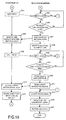
- the ERP client 30 of the user terminal 3 displays a login screen on a display device in accordance with the operation of the user (Fig. 16: step S1) .
- the ERP client 30 accepts an input of login data from the user, and transmits the login data to the application server 5 (step S3) .
- the login manager 507 of the application server 5 receives the login data from the user terminal 3, and temporarily stores it in a storage device such as a work memory area (not shown) or the like (step S5).
- the login manager 507 refers to the connected user number storage 515 and confirms the number of connected users (step S7).
- the login manager 507 judges whether the number of connected users is maximum (step S9). In the case where it is judged to be maximum (step S9: Yes route), the processing shifts to the processing of step S15 described later. On the other hand, in the case where it is judged not to be maximum (step S9: No route) , the login manager 507 refers to the user management table 509 and performs a user authentication processing (step S11) . Besides, the login manager 507 judges whether the login of the user is allowed on the basis of the result of the user authentication processing (step S13) . In the case where it is judged that the login is allowed (step S13: Yes route), the processing shifts to the processing of Fig. 17 through terminal A.
- step S13 the login manager 507 transmits data indicating that the login is impossible to the user terminal 3 (step S15).
- the ERP client 30 of the user terminal 3 receives the data indicating that the login is impossible from the application server 5, and displays a message indicating that the login could not be made on the display device (step S17) .
- the processing returns to the processing of the step S1.
- the user in addition to the case where the user is not authenticated, also in the case where the number of connected users is maximum, the user cannot perform a login.
- Fig. 17 shows processings after the transition through the terminal A.
- the login manager 507 of the application server 5 performs the login processing (Fig. 17: step S21) .
- the login manager 507 updates the number of connected users stored in the connected user number storage 515 (step S23) . That is, the number is incremented by 1.
- the login manager 507 confirms whether the data for the user is stored in the unsettled input data storage 513 on the basis of the user ID of the login user (step S25) .
- the login manager 507 judges whether the login user is a user who performs a new processing on the basis of the processing result of the step S25 (step S27) . Unless the data for the user is stored in the unsettled input data storage 513, the user is a user who performs the new processing.
- the login manager 507 extracts, for example, a screen ID for the new processing of a menu screen, or the like (step S29). For example, the ID is extracted from the setting data contained in the ERP server processor 501. Then, the processing shifts to the processing of step S33 described later.
- the login manager 507 extracts an inputting screen ID from the data for the user stored in the unsettled input data storage 513 (step S31).
- the inputting screen ID is the ID of the screen displayed on the display device of the user terminal 3 when the logoff is forcibly carried out.
- the login manager 507 performs an idle time setting processing (step S33) . Although the details of the idle time setting processing will be described later, as a result of the processing, the idle time for this login and standby time after the warning display are determined.
- the login manager 507 transmits the extracted screen ID to the user terminal 3 (step S35) .
- the ERP client 30 of the user terminal 3 receives the screen ID from the application server 5 (step S37) .
- the ERP client 30 displays the screen on the display device using the received screen ID and the data stored in the backup data storage 35 (step S39) .
- the screen corresponding to the received screen ID is specified.
- the input item data corresponding to the received screen ID is extracted from the backup data storage 35.
- data of the screen in which the input item data is embedded into corresponding input columns or the like is generated and is displayed on the display device.
- the screen in which input item data is not embedded is displayed as it is.
- the screen display is carried out using the data stored in the backup data storage 35, so that the user can perform the task processing from the last processing.
- the login manager 507 of the application server 5 starts to measure a no-input time (step S41).
- the no-input time is the time in which no input is made from the user. Then, the processing shifts to the processing of Fig. 18 through terminals B and C.
- Fig. 18 shows a processing after the transition through the terminals B and C.
- the ERP client 30 of the user terminal 3 is in a state of waiting an input from the user, and when there is an input from the user, the ERP client notifies the application server of an input event (Fig. 18: step S51) .
- a predetermined input event for example, a click of a "register” button occurs
- actual input data is contained in the notification data.
- the login manager 507 of the application server 5 judges whether there is an input from the user (step S53). In the case where it is judged that there is an input (step S53: Yes route) , the processing shifts to the processing of Fig. 19 through terminal D.
- step S53 the login manager 507 judges whether the no-input time whose measurement was started at step S41 (Fig. 17) exceeds the idle time determined at the step S33 (Fig. 17) (step S55). In the case where it is judged that the idle time does not exceed (step S55: No route), the processing returns to the step S53. On the other hand, in the case where it is judged that the no-input time exceeds the idle time (step S55: Yes route) , the login manager 507 transmits warning message data to the user terminal 3 (step S57) .
- the warning message data may be generated at the step S57, or previously prepared warning message data may be transmitted.
- instruction data to cause the warning message to be displayed is transmitted to the user terminal 3.
- the login manager 507 again starts to measure the no-input time (step S59).
- the login controller 31 included in the ERP client 30 of the user terminal 3 displays it on the display device (step S61). Then, the ERP client 30 of the user terminal 3 is again put into a state of waiting an input from the user, and when there is an input from the user, the ERP client notifies the application server of the input event (step S63).
- a predetermined input event for example, a click of the "register” button occurs, actual input data is contained in the notification data.
- the login manager 507 of the application server 5 judges whether there is an input from the user (step S65) .
- step S65: Yes route the processing shifts to the processing of Fig. 19 through terminal D.
- step S65: No route the login manager 507 judges whether the no-input time whose measurement was started at the step S59 exceeds the standby time after the warning display determined at the step S33 (Fig. 17) (step S67) . In the case where it is judged that the no-input time does not exceed (step S67: No route), the processing returns to the step S65.
- the login manager 507 associates the user ID of the user, who has not made an input for a time exceeding the standby time after the warning display, with the screen ID of the screen displayed on the display device of the user terminal 3 and stores them in the unsettled input data storage 513 (step S69).
- the user ID and screen ID are acquired by inquiring the ERP server processor 501, and the screen ID is stored as the inputting screen ID into the unsettled input data storage 513.
- the login manager 507 transmits logoff notification data to the user terminal 3 (step S71) .
- the logoff notification data may be generated at the step S71, or previously prepared logoff notification data may be transmitted.
- the login controller 31 included in the ERP client 30 of the user terminal 3 receives the logoff notification data from the application server 5 (step S73).
- the backup processor 33 included in the ERP client 30 of the user terminal 3 stores unsettled input data in the backup data storage 35 (step S75) . For example, the data as shown in Fig. 15 is stored. Then, the processing returns to the step S1 (Fig. 16) through terminal E.
- the login manager 507 of the application server 5 transmits logoff notification data at the step S71, and then performs a logoff processing (step S77).
- the login manager 507 updates the number of connected users stored in the connected user number storage 515 (step S79). That is, the number is decremented by 1.
- the ERP server processor 501 operating together with the login manager 507 notifies the log data generator 503 that the user has been made to log off, and the log data generator 503 records the log data relating to the logoff into the log data storage 505 (step S81). Then, the processing is ended.
- Fig. 19 shows a processing after the transition through the terminal D.
- the ERP server processor 501 of the application server 5 judges whether the input from the user indicates logoff (Fig. 19: step S91) .
- the processing shifts to the step S77 (Fig. 18) through terminal F.
- the ERP server processor 501 judges whether actual input data is contained in the notification data transmitted from the user terminal 3 (step S93) .
- step S93 In the case where it is judged that the actual input data is not contained in the notification data (step S93 : No route), the processing returns to the step S41 through terminal G (Fig. 17).
- step S93: Yes route the ERP server processor 501 performs a processing corresponding to the actual input data (step S95). There is also a case where the processing result is transmitted to the user terminal 3.
- the ERP server processor 501 judges whether a series of processings relating to the screens displayed on the display screen of the user terminal 3 are completed (step S97). In the case where it is judged that the processings for the screens are not completed (step S97: No route), the processing returns to the step S41 (Fig.
- step S97 Yes route
- the log data generator 503 records the log data relating to the processing of the screen into the log data storage 505 (step S99) .
- the ERP server processor 501 specifies an ID of a next screen displayed on the display screen of the user terminal 3 (step S101). Then, the processing shifts to the step S33 (Fig. 17) through terminal H.
- the usage efficiency of the user licenses can be improved by forcibly making the user who does not make an input for a time exceeding the standby time after the warning display log off.
- the burden of the user is reduced and the task efficiency can be improved by again displaying the screen displayed on the display device of the terminal just before the logoff.
- a screen ID (not including data under input) of a screen displayed on the display device of the terminal just before the logoff is associated with a user ID, and they are held at the server side (or held as a cookie at the user terminal side), and the screen just before the logoff is made to be displayed in response to re-login.
- the technique of the invention can be applied also to the ERP package using the Web technique.
- step S33 The details of the idle time setting processing (Fig. 17: step S33) are explained with reference to Fig. 20.
- setting of the priority is specified on the basis of one of the department, item, user level and order or is specified as "standard”.
- the priority is set to one of the priority month table 524, priority date table 525, and priority time table 526.
- the login manager 507 of the application server 5 confirms the data of priority set in one of the priority month table 524, priority date table 525 and priority time table 526 in the setting data storage 520 (Fig. 20: step S111). Then, the login manager 507 judges whether the priority is set for respective departments (step S113).
- the login manager 507 specifies the priority setting on the basis of the present date and time and the department to which the user belongs (step S115).
- the priority setting for example, "A" is specified. Then, the processing shifts to step S133 described later.
- step S113 the login manager 507 judges whether the priority is set for respective items (step S117). In the case where the priority is set for the respective items (step S117: Yes route), the login manager 507 specifies the priority setting on the basis of the present date and time and the item in charge of the user (step S119). Then, the processing shifts to the step S133 described later.
- step S117 the login manager 507 judges whether the priority is set for respective user levels (step S121) .
- step S121 Yes route
- the login manager 507 specifies the priority setting on the basis of the present date and time and the managerial position level of the user (step S123) . Then, the processing shits to the step S133 described later.
- step S121 No route
- step S121 the login manager 507 judges whether the priority is set for respective orders (step S125). In the case where it is judged that the priority is not set for the respective orders (step S125: No route), the login manager 507 specifies the priority setting as "standard” (step S127). Then, the processing shifts to the step S133 described later.
- the login manager 507 specifies the order on the basis of the ID of the screen displayed on the display device of the user terminal 3 (step S129). There is also a case where inquiry is made to the ERP server processor 501. Besides, the login manager 507 specifies the priority setting on the basis of the present date and time and the order (step S131).
- the login manager 507 specifies the task processing on the basis of the ID of the screen displayed on the display device of the user terminal 3 (step S133). For example, in the case where the screen ID is "A1-1", it is possible to specify that the task processing is "A1". It may be specified using an association table or the like.
- the login manager 507 refers to the idle time table 521 on the basis of the task processing specified at step S133 and the department to which the user belongs, extracts the pertinent idle time, and temporarily stores it in a storage device such as a work memory area (not shown) or the like (step S135) . For example, "5 (minutes)" is extracted.
- the login manager 507 refers to the standby time table 522 on the basis of the department to which the user belongs, extracts the pertinent standby time after the warning display, and temporarily stores it in the storage device such as the work memory area (not shown) or the like (step S137) For example, "4 (minutes)" is extracted.
- the login manager 507 extracts the priority rate from the priority rate table 523 on the basis of the specified priority setting (step S139). For example, "120%" is extracted.
- the login manager 507 calculates a value which is obtained by multiplying the idle time extracted at the step S 135 by the priority rate extracted at the step S139, and a value which is obtained by multiplying the standby time after the warning display extracted at the step S137 by the priority rate extracted at the step S139, and temporarily stores them in the storage device such as the work memory area (not shown) or the like (step S141). For example, “6 minutes (5 minutes x 120 0) " and “4. 8 minutes (4 minutes x 120%) " are calculated. Then, the processing returns to the original processing. In this way, the idle time setting processing is performed, and the idle time and standby time after the warning display, which correspond to this login, are determined.
- the setting time corrector 511 generates data of the first processing time table 535 on the basis of data of the log data storage 505 and summation period table 533, and stores it (step S151). For example, on the basis of log data for a half year, an average value of processing times for each task processing is calculated for each user and is stored in the first processing time table 535.
- the setting time corrector 511 generates data of the second processing time table 537 on the basis of the data of the first processing time table 535 stored at the step S151 and stores it (step S153) . That is, data for respective departments is generated on the basis of data for the respective users.
- the setting time corrector 511 compares the data of the second processing time table 537 stored at the step S153 with the data of the idle time table 521 and standby time table 522 (step S155).
- the setting time corrector 511 updates the idle time table 521 and standby time table 522 on the basis of the comparison result at the step S155 and data of the judgment reference table 531 (step S157).
- a specific example is as shown in the description of Fig. 14.
- the setting time correction processing is performed in this way.
- this processing for example, in the case where initial values set by the system administrator are not suitable, or in the case where the user becomes accustomed to the operation and comes to have an excessive margin in reference time, the reference time can be corrected.
- the invention is not limited to this.
- the table structures shown in Figs. 3 to 6, Figs. 7A to 7D, Figs. 8A to 8D, Figs. 9A to 9D, and Figs. 11 to 15 are examples, and different structures may be adopted for storing similar data, and data items may be added or deleted as the need arises.
- the log data shown in Fig. 10 is also an example, and elements to be recorded in the log are not limited to the elements shown in Fig. 10.
- the functional block configurations of the application server and user terminal shown in Fig. 1 are examples, and there is a case where they are different from actual program module structures.
- the application server may be constructed of plural servers or computers. Further,theprocessing flows shown in Figs. 16 to 21 are also examples, and the sequence of the processing may be changed within the range where similar processing results can be obtained, or a step may be added or deleted as the need arises.
Landscapes
- Engineering & Computer Science (AREA)
- Theoretical Computer Science (AREA)
- Software Systems (AREA)
- Computer Security & Cryptography (AREA)
- Computer Hardware Design (AREA)
- Physics & Mathematics (AREA)
- General Engineering & Computer Science (AREA)
- General Physics & Mathematics (AREA)
- Multimedia (AREA)
- Technology Law (AREA)
- Management, Administration, Business Operations System, And Electronic Commerce (AREA)
- Information Transfer Between Computers (AREA)
Applications Claiming Priority (2)
| Application Number | Priority Date | Filing Date | Title |
|---|---|---|---|
| JP2004072016A JP4290042B2 (ja) | 2004-03-15 | 2004-03-15 | ログイン管理プログラム、ログイン管理プログラムが記録された媒体、ログイン管理装置、及びログイン管理方法 |
| JP2004072016 | 2004-03-15 |
Publications (2)
| Publication Number | Publication Date |
|---|---|
| EP1577731A2 true EP1577731A2 (de) | 2005-09-21 |
| EP1577731A3 EP1577731A3 (de) | 2006-09-20 |
Family
ID=34836483
Family Applications (1)
| Application Number | Title | Priority Date | Filing Date |
|---|---|---|---|
| EP04254544A Withdrawn EP1577731A3 (de) | 2004-03-15 | 2004-07-29 | Technik der Verwaltung der Anmeldung |
Country Status (3)
| Country | Link |
|---|---|
| US (1) | US7676749B2 (de) |
| EP (1) | EP1577731A3 (de) |
| JP (1) | JP4290042B2 (de) |
Cited By (1)
| Publication number | Priority date | Publication date | Assignee | Title |
|---|---|---|---|---|
| EP2637076A3 (de) * | 2012-03-05 | 2015-08-05 | Ricoh Company, Ltd. | Automatische Beendigung interaktiver Weißwandtafelsitzungen |
Families Citing this family (15)
| Publication number | Priority date | Publication date | Assignee | Title |
|---|---|---|---|---|
| JPH0365965A (ja) * | 1989-08-04 | 1991-03-20 | Ricoh Co Ltd | コロナ放電装置 |
| US20040254884A1 (en) * | 2002-12-20 | 2004-12-16 | Sap Aktiengesellschaft | Content catalog and application designer framework |
| JP2008044264A (ja) * | 2006-08-18 | 2008-02-28 | Oki Data Corp | 画像形成装置 |
| US20080075056A1 (en) * | 2006-09-22 | 2008-03-27 | Timothy Thome | Mobile wireless device and processes for managing high-speed data services |
| JP2008242676A (ja) * | 2007-03-27 | 2008-10-09 | Hitachi Ltd | ウェブログイン制限システム |
| US8108911B2 (en) * | 2007-11-01 | 2012-01-31 | Comcast Cable Holdings, Llc | Method and system for directing user between captive and open domains |
| KR101450778B1 (ko) * | 2008-01-31 | 2014-10-14 | 삼성전자주식회사 | 제어국의 기지국 유휴 시간 설정 방법 및 그 제어국 |
| US9910708B2 (en) * | 2008-08-28 | 2018-03-06 | Red Hat, Inc. | Promotion of calculations to cloud-based computation resources |
| JP5555998B2 (ja) * | 2008-10-02 | 2014-07-23 | 富士通株式会社 | 環境負荷評価システム、サーバおよび環境負荷評価方法 |
| US8856376B1 (en) * | 2008-12-18 | 2014-10-07 | Bank Of America Corporation | Stabilization tool for a high-capacity network infrastructure |
| JP2010277497A (ja) * | 2009-06-01 | 2010-12-09 | Nec Corp | 業務管理システム、業務管理方法、業務管理プログラムおよびプログラム記録媒体 |
| KR101536785B1 (ko) * | 2010-10-29 | 2015-07-17 | 네이버 주식회사 | 멀티 로그인을 이용한 통합 커뮤니케이션 시스템 및 방법 그리고 통합 커뮤니케이션 툴의 동작을 제어하는 단말기 및 단말기에서의 커뮤니케이션 방법 |
| KR102002541B1 (ko) * | 2013-03-08 | 2019-10-01 | 휴렛-팩커드 디벨롭먼트 컴퍼니, 엘.피. | 클라우드 기반 어플리케이션의 로그인 관리 방법 및 이를 수행하기 위한 화상형성장치 |
| US10348737B2 (en) | 2016-03-08 | 2019-07-09 | International Business Machines Corporation | Login performance |
| JP7295793B2 (ja) * | 2019-12-20 | 2023-06-21 | 株式会社日立製作所 | ログオン管理方法及びログオン管理装置 |
Citations (1)
| Publication number | Priority date | Publication date | Assignee | Title |
|---|---|---|---|---|
| US20040010440A1 (en) * | 2002-07-10 | 2004-01-15 | Rohan Lenard | Predictive software license balancing |
Family Cites Families (14)
| Publication number | Priority date | Publication date | Assignee | Title |
|---|---|---|---|---|
| EP0513484A3 (en) | 1991-03-19 | 1993-04-21 | Bull Hn Information Systems Inc. | Digital network access authorisation |
| US5845065A (en) * | 1994-11-15 | 1998-12-01 | Wrq, Inc. | Network license compliance apparatus and method |
| JPH10240687A (ja) | 1997-02-28 | 1998-09-11 | Tec Corp | ネットワークシステム |
| US5937159A (en) * | 1997-03-28 | 1999-08-10 | Data General Corporation | Secure computer system |
| JP2000315189A (ja) | 1999-04-30 | 2000-11-14 | Nippon Steel Corp | データベース検索システム及びデータベース検索方法 |
| US7020690B1 (en) * | 1999-10-19 | 2006-03-28 | Netzero, Inc. | Inactivity timer for an internet client |
| GB9925289D0 (en) * | 1999-10-27 | 1999-12-29 | Ibm | Method and means for adjusting the timing of user-activity-dependent changes of operational state of an apparatus |
| JP2001229096A (ja) | 2000-02-17 | 2001-08-24 | Sanyo Electric Co Ltd | ネットワークシステムの強制終了装置 |
| JP2001290641A (ja) | 2000-04-10 | 2001-10-19 | A & I System Kk | アプリケーションソフトウェア共用システム |
| JP2001306504A (ja) | 2000-04-21 | 2001-11-02 | Casio Comput Co Ltd | コンピュータ・システム、サーバおよび端末装置 |
| JP2002222171A (ja) | 2001-01-29 | 2002-08-09 | Jsr Corp | 情報処理セキュリティシステム |
| JP4196584B2 (ja) * | 2002-03-18 | 2008-12-17 | 富士機械製造株式会社 | 管理調整モードプロテクション機能を備えた回路基板製造装置及びその運転方法 |
| US7644434B2 (en) * | 2002-04-25 | 2010-01-05 | Applied Identity, Inc. | Computer security system |
| US7111157B1 (en) * | 2002-05-08 | 2006-09-19 | 3Pardata, Inc. | Spurious input detection for firmware |
-
2004
- 2004-03-15 JP JP2004072016A patent/JP4290042B2/ja not_active Expired - Lifetime
- 2004-07-27 US US10/899,067 patent/US7676749B2/en not_active Expired - Fee Related
- 2004-07-29 EP EP04254544A patent/EP1577731A3/de not_active Withdrawn
Patent Citations (1)
| Publication number | Priority date | Publication date | Assignee | Title |
|---|---|---|---|---|
| US20040010440A1 (en) * | 2002-07-10 | 2004-01-15 | Rohan Lenard | Predictive software license balancing |
Cited By (1)
| Publication number | Priority date | Publication date | Assignee | Title |
|---|---|---|---|---|
| EP2637076A3 (de) * | 2012-03-05 | 2015-08-05 | Ricoh Company, Ltd. | Automatische Beendigung interaktiver Weißwandtafelsitzungen |
Also Published As
| Publication number | Publication date |
|---|---|
| JP4290042B2 (ja) | 2009-07-01 |
| JP2005258977A (ja) | 2005-09-22 |
| EP1577731A3 (de) | 2006-09-20 |
| US20050204158A1 (en) | 2005-09-15 |
| US7676749B2 (en) | 2010-03-09 |
Similar Documents
| Publication | Publication Date | Title |
|---|---|---|
| EP1577731A2 (de) | Technik der Verwaltung der Anmeldung | |
| US8725886B1 (en) | Provisioned virtual computing | |
| US7660731B2 (en) | Method and apparatus for technology resource management | |
| JP4255317B2 (ja) | 運用監視方法及び実施システム並びに処理プログラム | |
| WO2019056710A1 (zh) | 供应商推荐方法、装置及计算机可读存储介质 | |
| US20080319864A1 (en) | Method of dynamically routing food items through a restaurant kitchen | |
| US20020116301A1 (en) | Automatic consumption based replenishment of supply chain | |
| US7979520B2 (en) | Prescriptive architecture recommendations | |
| JP2002526819A (ja) | クロスアプリケーションタイムシート | |
| US6963828B1 (en) | Metafarm sizer configuration optimization method for thin client sizing tool | |
| US20110010343A1 (en) | Optimization and staging method and system | |
| CN1770186A (zh) | 交换工作流的计算机系统及方法 | |
| JP3953479B2 (ja) | 使用電力監視システムおよび負荷率演算表示方法 | |
| US8407430B2 (en) | Analysis technique of computer system | |
| JP2007179365A (ja) | サービスの評価の方法、システム、コンピュータ・プログラム | |
| JP2003303277A (ja) | 製品の調達支援情報の提供方法およびシステム | |
| JP6097666B2 (ja) | ジョブ管理システム | |
| US20060218553A1 (en) | Potentially hazardous material request and approve methods and apparatuses | |
| JP2005346220A (ja) | ソリューション設計方法及びソリューション設計計算機システム並びに記録媒体 | |
| JP5776084B2 (ja) | 配席装置、配席方法及び配席プログラム | |
| JP2004118832A (ja) | 保険の挙績又は販売手数料配分のための情報処理方法及び装置 | |
| JP2005227905A (ja) | ソリューション契約支援システム及びソリューション契約支援方法 | |
| JP2007052605A (ja) | 価格提示装置及び価格提示プログラム | |
| JP7230458B2 (ja) | 情報処理システム、情報処理装置、プログラム、及び推奨商品判定方法 | |
| CN100373340C (zh) | 分布计算机系统管理方法 |
Legal Events
| Date | Code | Title | Description |
|---|---|---|---|
| PUAI | Public reference made under article 153(3) epc to a published international application that has entered the european phase |
Free format text: ORIGINAL CODE: 0009012 |
|
| AK | Designated contracting states |
Kind code of ref document: A2 Designated state(s): AT BE BG CH CY CZ DE DK EE ES FI FR GB GR HU IE IT LI LU MC NL PL PT RO SE SI SK TR |
|
| AX | Request for extension of the european patent |
Extension state: AL HR LT LV MK |
|
| PUAL | Search report despatched |
Free format text: ORIGINAL CODE: 0009013 |
|
| AK | Designated contracting states |
Kind code of ref document: A3 Designated state(s): AT BE BG CH CY CZ DE DK EE ES FI FR GB GR HU IE IT LI LU MC NL PL PT RO SE SI SK TR |
|
| AX | Request for extension of the european patent |
Extension state: AL HR LT LV MK |
|
| 17P | Request for examination filed |
Effective date: 20070314 |
|
| 17Q | First examination report despatched |
Effective date: 20070419 |
|
| AKX | Designation fees paid |
Designated state(s): DE FR GB |
|
| STAA | Information on the status of an ep patent application or granted ep patent |
Free format text: STATUS: THE APPLICATION IS DEEMED TO BE WITHDRAWN |
|
| 18D | Application deemed to be withdrawn |
Effective date: 20081113 |