EP1577634A1 - Treibladungsanzünder - Google Patents
Treibladungsanzünder Download PDFInfo
- Publication number
- EP1577634A1 EP1577634A1 EP05001511A EP05001511A EP1577634A1 EP 1577634 A1 EP1577634 A1 EP 1577634A1 EP 05001511 A EP05001511 A EP 05001511A EP 05001511 A EP05001511 A EP 05001511A EP 1577634 A1 EP1577634 A1 EP 1577634A1
- Authority
- EP
- European Patent Office
- Prior art keywords
- ignition
- tube
- closure cap
- protective tube
- charge
- Prior art date
- Legal status (The legal status is an assumption and is not a legal conclusion. Google has not performed a legal analysis and makes no representation as to the accuracy of the status listed.)
- Granted
Links
- 230000001141 propulsive effect Effects 0.000 title 1
- 230000001681 protective effect Effects 0.000 claims abstract description 30
- 239000003380 propellant Substances 0.000 claims abstract description 10
- 230000001747 exhibiting effect Effects 0.000 claims description 2
- 230000007613 environmental effect Effects 0.000 description 3
- 239000011888 foil Substances 0.000 description 2
- 239000002184 metal Substances 0.000 description 2
- 229910000831 Steel Inorganic materials 0.000 description 1
- 230000001419 dependent effect Effects 0.000 description 1
- 239000002360 explosive Substances 0.000 description 1
- 239000000463 material Substances 0.000 description 1
- 239000000843 powder Substances 0.000 description 1
- 238000007789 sealing Methods 0.000 description 1
- 239000010959 steel Substances 0.000 description 1
- 230000000007 visual effect Effects 0.000 description 1
- 238000004260 weight control Methods 0.000 description 1
Images


Classifications
-
- F—MECHANICAL ENGINEERING; LIGHTING; HEATING; WEAPONS; BLASTING
- F42—AMMUNITION; BLASTING
- F42C—AMMUNITION FUZES; ARMING OR SAFETY MEANS THEREFOR
- F42C19/00—Details of fuzes
- F42C19/08—Primers; Detonators
- F42C19/0823—Primers or igniters for the initiation or the propellant charge in a cartridged ammunition
- F42C19/0826—Primers or igniters for the initiation or the propellant charge in a cartridged ammunition comprising an elongated perforated tube, i.e. flame tube, for the transmission of the initial energy to the propellant charge, e.g. used for artillery shells and kinetic energy penetrators
Definitions
- the invention relates to a propellant charge for cartridged ammunition with a Headboard and an adjoining the headboard, ignition openings exhibiting Ignition tube in which a Anzündladung is arranged.
- TLAnz propellant charge igniter
- a thin-walled protective tube made of a plastic or to arrange metal foil, which on its side facing away from the head part is closed and its outer wall rests against the inner wall of the jacket tube and the Ignition openings concealed on the inside.
- the invention has for its object to provide a propellant charge igniter, the one Ignition with an internally arranged protective tube has, which even at elevated Moisture storage over a longer period the ignition charge safe against external Environmental influences seals.
- the invention is based essentially on the idea of the protective tube on his Head end facing by a non-positively connected to the protective tube Seal cap against moisture.
- thermowell with ignition charge and this unit on Waterproofness e.g. through a visual check and weight control too check.
- the closure cap may be formed, for example, as a flat plate and with the glued or welded to the front part facing the front edge of the protective tube be.
- cap hat-shaped with and without edge brim train it is also possible, the cap hat-shaped with and without edge brim train.
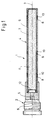
- a propellant charge for large-caliber cartridges ammunition referred to, consisting essentially of a head part 2 and a towards it in the direction the longitudinal axis 3 of the lighter 1 subsequent ignition tube 4 is made.
- the head part 2 which is an unillustrated primer and a booster charge 5 contains with an external thread 6 for screwing the propellant charge igniter 1 in the ground the corresponding cartridge (not shown) provided.
- the ignition tube 4 is composed of a jacket tube 7 made of steel with ignition openings 8 and an inside arranged seal in the form of a front side closed Protective tube 9 (e.g., a plastic or metal foil) together.
- a jacket tube 7 made of steel with ignition openings 8 and an inside arranged seal in the form of a front side closed Protective tube 9 (e.g., a plastic or metal foil) together.
- the protective tube 9 is with a powder or filled rod-shaped ignition charge 11 and covers the ignition openings 8 inside from.
- a e.g. hat-shaped cap 12 On its head part 2 facing the end of the protective tube 9 according to the invention by a e.g. hat-shaped cap 12 so tightly closed that no moisture can penetrate into the interior of the protective tube 9 in this area.
- FIGS 2-6 show different embodiments of such caps.
- closure caps 12 ' which are plate-shaped and glued to the head portion 2 of the TLAnz facing edge region 13 of the protective tube 9 or welded.
- the cap 12 ' can directly frontally with the Protective tube 9 be connected ( Figure 2) or it is from the folded edge area 13 of the protective tube 9 enclosed ( Figure 3).
- FIGS. 4 and 5 show hat-shaped closure caps 12 and 12 " .
- the closure cap 12 is provided with a brim 14 which is enclosed by the turned over edge region 13 of the protective tube 9.
- FIG. 6 shows a further embodiment of a hat-shaped closure cap 12 '" , which is provided on its side of the bottom 15 facing the ignition charge 11 with circular depressions 16 forming predetermined breaking points.
- the depressions do not necessarily have to be circular but may be another form, e.g. a circle-shaped figure, exhibit.
Landscapes
- Engineering & Computer Science (AREA)
- General Engineering & Computer Science (AREA)
- Lighters Containing Fuel (AREA)
- Air Bags (AREA)
- Ignition Installations For Internal Combustion Engines (AREA)
Abstract
Description
- 1
- Treibladungsanzünder
- 2
- Kopfteil
- 3
- Längsachse
- 4
- Anzündrohr
- 5
- Verstärkerladung
- 6
- Außengewinde
- 7
- Mantelrohr
- 8
- Anzündöffnung
- 9
- Schutzrohr
- 10
- Stopfen, Element
- 11
- Anzündladung
- 12-12"'
- Verschlußkappen
- 13
- Randbereich
- 14
- Krempe
- 15
- Boden
- 16,16'
- Vertiefungen
Claims (7)
- Treibladungsanzünder für patronierte Munition mit einem Kopfteil (2) und einem sich an das Kopfteil (2) anschließendes Anzündrohr (4), in dem eine Anzündladung (11) angeordnet ist, mit den Merkmalen:a) das Anzündrohr (4) umfaßt ein Anzündöffnungen (8) aufweisendes Mantelrohr (7) und ein die Anzündladung (11) enthaltendes, in dem Mantelrohr (7) angeordnetes dünnwandiges Schutzrohr (9), dessen Außenwand an der Innenwand des Mantelrohres (7) anliegt und die Anzündöffnungen (8) innenseitig verdeckt;b) das Schutzrohr (9) ist auf seinem dem Kopfteil (2) zugewandten Ende durch eine mit dem Schutzrohr (9) kraftschlüssig verbundene Verschlußkappe (12-12"') gegen Feuchtigkeit abgedichtet.
- Treibladungsanzünder nach Anspruch 1, dadurch gekennzeichnet, daß die Verschlußkappe (12') als ebene Platte ausgebildet und mit dem dem Kopfteil (2) zugewandten vorderen Randbereich (13) des Schutzrohres (9) verbunden ist.
- Treibladungsanzünder nach Anspruch 1, dadurch gekennzeichnet, daß die Verschlußkappe (12; 12"') hutförmig ausgebildet ist, wobei der Boden (15) der Verschlußkappe (12; 12"') an die Anzündladung (11) angrenzt und die Seitenwände der Verschlußkappe (12; 12"') sich bis zum stirnseitigen Randbereich (13) des Schutzrohres (9) erstrecken.
- Treibladungsanzünder nach Anspruch 3, dadurch gekennzeichnet, daß die hutförmige Verschlußkappe (12;12''') randseitig mit einer Krempe (14) versehen ist, welche entweder auf dem stirnseitigen Randbereich (13) des Schutzrohres (9) aufliegt oder welche von dem umgeschlagenen Randbereich (13) des Schutzrohres (9) umschlossen ist.
- Treibladungsanzünder nach Anspruch 1, dadurch gekennzeichnet, daß die Verschlußkappe (12") hutförmig ausgebildet ist, wobei der Boden kopfteilseitig angeordnet ist und die Seitenwände der Verschlußkappe (12") sich bis in den Bereich der Anzündladung (11) erstrecken.
- Treibladungsanzünder nach einem der Ansprüche 2 bis 5, dadurch gekennzeichnet, daß die der Anzündladung (11) zugewandte Seite der Verschlußkappe (12"') mit Sollbruchstellen bildenden Vertiefungen (16, 16') versehen ist.
- Treibladungsanzünder nach einem der Ansprüche 1 bis 6, dadurch gekennzeichnet, daß die Anzündöffnungen (8) des Mantelrohres (7) mit stopfen- oder klipsartigen Elementen (10) verschlossen sind.
Applications Claiming Priority (2)
| Application Number | Priority Date | Filing Date | Title |
|---|---|---|---|
| DE102004012934 | 2004-03-17 | ||
| DE102004012934A DE102004012934A1 (de) | 2004-03-17 | 2004-03-17 | Treibladungsanzünder |
Publications (2)
| Publication Number | Publication Date |
|---|---|
| EP1577634A1 true EP1577634A1 (de) | 2005-09-21 |
| EP1577634B1 EP1577634B1 (de) | 2011-06-01 |
Family
ID=34833149
Family Applications (1)
| Application Number | Title | Priority Date | Filing Date |
|---|---|---|---|
| EP05001511A Expired - Lifetime EP1577634B1 (de) | 2004-03-17 | 2005-01-26 | Treibladungsanzünder |
Country Status (3)
| Country | Link |
|---|---|
| EP (1) | EP1577634B1 (de) |
| AT (1) | ATE511627T1 (de) |
| DE (1) | DE102004012934A1 (de) |
Cited By (2)
| Publication number | Priority date | Publication date | Assignee | Title |
|---|---|---|---|---|
| WO2009024243A1 (de) * | 2007-08-22 | 2009-02-26 | Rheinmetall Waffe Munition Gmbh | Treibladungsanzünder |
| DE102022118632A1 (de) * | 2022-07-26 | 2024-02-01 | Nitrochemie Aschau Gmbh | Hülse und Artillerieladung |
Families Citing this family (1)
| Publication number | Priority date | Publication date | Assignee | Title |
|---|---|---|---|---|
| DE102009052753B4 (de) | 2008-11-13 | 2022-01-20 | Ruag Ammotec Gmbh | Pyrotechnischer Anzünder |
Citations (9)
| Publication number | Priority date | Publication date | Assignee | Title |
|---|---|---|---|---|
| FR866800A (fr) * | 1940-05-09 | 1941-09-03 | Procédé et dispositifs de protection des corps de gaine | |
| GB605135A (en) * | 1945-12-14 | 1948-07-16 | John Norman Pring | Improvements in or relating to magazines or containers for cartridge priming compositions |
| US2446187A (en) * | 1945-05-07 | 1948-08-03 | Leo T Meister | Lined igniter-charge tube |
| DE2344979A1 (de) * | 1973-09-06 | 1975-03-20 | Dynamit Nobel Ag | Boerdelverschluss, insbesondere fuer treibladungsanzuender |
| FR2343987A1 (fr) * | 1976-03-08 | 1977-10-07 | France Etat | Tube allumeur, notamment pour munition d'artillerie |
| US4284196A (en) * | 1978-10-04 | 1981-08-18 | Nitro Nobel Ab | Tubular container for viscous, viscous-elastic, plastic products as well as for powder or granular products |
| EP0390756A2 (de) * | 1989-03-02 | 1990-10-03 | Ab Bofors | Treibladungszünder |
| EP1039260A2 (de) * | 1996-08-02 | 2000-09-27 | Rheinmetall W & M GmbH | Treibladungsanzünder |
| WO2001071274A1 (fr) * | 2000-03-23 | 2001-09-27 | Giat Industries | Tube allumeur pour une munition d'artillerie |
-
2004
- 2004-03-17 DE DE102004012934A patent/DE102004012934A1/de not_active Withdrawn
-
2005
- 2005-01-26 EP EP05001511A patent/EP1577634B1/de not_active Expired - Lifetime
- 2005-01-26 AT AT05001511T patent/ATE511627T1/de active
Patent Citations (9)
| Publication number | Priority date | Publication date | Assignee | Title |
|---|---|---|---|---|
| FR866800A (fr) * | 1940-05-09 | 1941-09-03 | Procédé et dispositifs de protection des corps de gaine | |
| US2446187A (en) * | 1945-05-07 | 1948-08-03 | Leo T Meister | Lined igniter-charge tube |
| GB605135A (en) * | 1945-12-14 | 1948-07-16 | John Norman Pring | Improvements in or relating to magazines or containers for cartridge priming compositions |
| DE2344979A1 (de) * | 1973-09-06 | 1975-03-20 | Dynamit Nobel Ag | Boerdelverschluss, insbesondere fuer treibladungsanzuender |
| FR2343987A1 (fr) * | 1976-03-08 | 1977-10-07 | France Etat | Tube allumeur, notamment pour munition d'artillerie |
| US4284196A (en) * | 1978-10-04 | 1981-08-18 | Nitro Nobel Ab | Tubular container for viscous, viscous-elastic, plastic products as well as for powder or granular products |
| EP0390756A2 (de) * | 1989-03-02 | 1990-10-03 | Ab Bofors | Treibladungszünder |
| EP1039260A2 (de) * | 1996-08-02 | 2000-09-27 | Rheinmetall W & M GmbH | Treibladungsanzünder |
| WO2001071274A1 (fr) * | 2000-03-23 | 2001-09-27 | Giat Industries | Tube allumeur pour une munition d'artillerie |
Cited By (4)
| Publication number | Priority date | Publication date | Assignee | Title |
|---|---|---|---|---|
| WO2009024243A1 (de) * | 2007-08-22 | 2009-02-26 | Rheinmetall Waffe Munition Gmbh | Treibladungsanzünder |
| US9016203B2 (en) | 2007-08-22 | 2015-04-28 | Rheinmetall Waffe Munition Gmbh | Propellant charge igniter |
| DE102022118632A1 (de) * | 2022-07-26 | 2024-02-01 | Nitrochemie Aschau Gmbh | Hülse und Artillerieladung |
| DE102022118632B4 (de) * | 2022-07-26 | 2024-03-21 | Nitrochemie Aschau Gmbh | Hülse und Artillerieladung |
Also Published As
| Publication number | Publication date |
|---|---|
| EP1577634B1 (de) | 2011-06-01 |
| DE102004012934A1 (de) | 2005-10-06 |
| ATE511627T1 (de) | 2011-06-15 |
Similar Documents
| Publication | Publication Date | Title |
|---|---|---|
| DE69620509T2 (de) | Behälter für grosskalibrige munition | |
| DE2842797A1 (de) | Wurfkoerper | |
| WO2012126554A1 (de) | Insensitive munition | |
| EP1067358B1 (de) | Treibladungsanzünder | |
| EP1577634B1 (de) | Treibladungsanzünder | |
| EP1484574A1 (de) | Bombenschutzbehälter | |
| DE2932922C2 (de) | Nebelwurfkörper | |
| DE2911595A1 (de) | Anordnung an einer sprengkapsel einer niedrigenergiezuendschnur | |
| EP3006889B1 (de) | Chemischer zünder mit elektrischer auslösung | |
| DE1728018A1 (de) | Halbbrennbare Munition fuer Verschluesse der Bauart mit offener Kammer | |
| DE1814099C3 (de) | Explosionssicherer Becherkondensator | |
| DE2031940A1 (de) | Sicherheitsvorrichtung fur Handgranaten | |
| DE2446832C2 (de) | Zündvorrichtung für Werferrohre zur Zündung der Antriebsladung eines Projektils | |
| EP3479051A1 (de) | Irritationskörper und verfahren zu dessen herstellung | |
| DE60107181T2 (de) | Verfahren zum neutralisieren einer nutzlast | |
| EP0733874B1 (de) | Geschossimulationsmittel und Verfahren zur Herstellung desselben | |
| EP2146179A2 (de) | Nebeltopf | |
| AT396304B (de) | Uebungs-handgranatenzuender | |
| DE3048621A1 (de) | "dueppel-patrone" | |
| EP1471268A1 (de) | Trennschraube | |
| DE3434650A1 (de) | In ein geschoss einsetzbarer behaelter | |
| DE1923046U (de) | Knallkapsel. | |
| EP2705328A1 (de) | Wirkmassenbehälter | |
| DE8620901U1 (de) | Patrone | |
| DE8903486U1 (de) | Akkumulator |
Legal Events
| Date | Code | Title | Description |
|---|---|---|---|
| PUAI | Public reference made under article 153(3) epc to a published international application that has entered the european phase |
Free format text: ORIGINAL CODE: 0009012 |
|
| AK | Designated contracting states |
Kind code of ref document: A1 Designated state(s): AT BE BG CH CY CZ DE DK EE ES FI FR GB GR HU IE IS IT LI LT LU MC NL PL PT RO SE SI SK TR |
|
| AX | Request for extension of the european patent |
Extension state: AL BA HR LV MK YU |
|
| 17P | Request for examination filed |
Effective date: 20060307 |
|
| AKX | Designation fees paid |
Designated state(s): AT BE BG CH CY CZ DE DK EE ES FI FR GB GR HU IE IS IT LI LT LU MC NL PL PT RO SE SI SK TR |
|
| RAP1 | Party data changed (applicant data changed or rights of an application transferred) |
Owner name: RHEINMETALL WAFFE MUNITION GMBH |
|
| GRAP | Despatch of communication of intention to grant a patent |
Free format text: ORIGINAL CODE: EPIDOSNIGR1 |
|
| GRAS | Grant fee paid |
Free format text: ORIGINAL CODE: EPIDOSNIGR3 |
|
| GRAA | (expected) grant |
Free format text: ORIGINAL CODE: 0009210 |
|
| AK | Designated contracting states |
Kind code of ref document: B1 Designated state(s): AT BE BG CH CY CZ DE DK EE ES FI FR GB GR HU IE IS IT LI LT LU MC NL PL PT RO SE SI SK TR |
|
| REG | Reference to a national code |
Ref country code: GB Ref legal event code: FG4D Free format text: NOT ENGLISH |
|
| REG | Reference to a national code |
Ref country code: CH Ref legal event code: EP |
|
| REG | Reference to a national code |
Ref country code: IE Ref legal event code: FG4D Free format text: LANGUAGE OF EP DOCUMENT: GERMAN |
|
| REG | Reference to a national code |
Ref country code: DE Ref legal event code: R096 Ref document number: 502005011448 Country of ref document: DE Effective date: 20110714 |
|
| REG | Reference to a national code |
Ref country code: NL Ref legal event code: VDEP Effective date: 20110601 |
|
| PG25 | Lapsed in a contracting state [announced via postgrant information from national office to epo] |
Ref country code: LT Free format text: LAPSE BECAUSE OF FAILURE TO SUBMIT A TRANSLATION OF THE DESCRIPTION OR TO PAY THE FEE WITHIN THE PRESCRIBED TIME-LIMIT Effective date: 20110601 Ref country code: SE Free format text: LAPSE BECAUSE OF FAILURE TO SUBMIT A TRANSLATION OF THE DESCRIPTION OR TO PAY THE FEE WITHIN THE PRESCRIBED TIME-LIMIT Effective date: 20110601 |
|
| PG25 | Lapsed in a contracting state [announced via postgrant information from national office to epo] |
Ref country code: FI Free format text: LAPSE BECAUSE OF FAILURE TO SUBMIT A TRANSLATION OF THE DESCRIPTION OR TO PAY THE FEE WITHIN THE PRESCRIBED TIME-LIMIT Effective date: 20110601 Ref country code: CY Free format text: LAPSE BECAUSE OF FAILURE TO SUBMIT A TRANSLATION OF THE DESCRIPTION OR TO PAY THE FEE WITHIN THE PRESCRIBED TIME-LIMIT Effective date: 20110601 Ref country code: GR Free format text: LAPSE BECAUSE OF FAILURE TO SUBMIT A TRANSLATION OF THE DESCRIPTION OR TO PAY THE FEE WITHIN THE PRESCRIBED TIME-LIMIT Effective date: 20110902 Ref country code: ES Free format text: LAPSE BECAUSE OF FAILURE TO SUBMIT A TRANSLATION OF THE DESCRIPTION OR TO PAY THE FEE WITHIN THE PRESCRIBED TIME-LIMIT Effective date: 20110912 Ref country code: SI Free format text: LAPSE BECAUSE OF FAILURE TO SUBMIT A TRANSLATION OF THE DESCRIPTION OR TO PAY THE FEE WITHIN THE PRESCRIBED TIME-LIMIT Effective date: 20110601 |
|
| REG | Reference to a national code |
Ref country code: IE Ref legal event code: FD4D |
|
| PG25 | Lapsed in a contracting state [announced via postgrant information from national office to epo] |
Ref country code: NL Free format text: LAPSE BECAUSE OF FAILURE TO SUBMIT A TRANSLATION OF THE DESCRIPTION OR TO PAY THE FEE WITHIN THE PRESCRIBED TIME-LIMIT Effective date: 20110601 |
|
| PG25 | Lapsed in a contracting state [announced via postgrant information from national office to epo] |
Ref country code: PT Free format text: LAPSE BECAUSE OF FAILURE TO SUBMIT A TRANSLATION OF THE DESCRIPTION OR TO PAY THE FEE WITHIN THE PRESCRIBED TIME-LIMIT Effective date: 20111003 Ref country code: CZ Free format text: LAPSE BECAUSE OF FAILURE TO SUBMIT A TRANSLATION OF THE DESCRIPTION OR TO PAY THE FEE WITHIN THE PRESCRIBED TIME-LIMIT Effective date: 20110601 Ref country code: IE Free format text: LAPSE BECAUSE OF FAILURE TO SUBMIT A TRANSLATION OF THE DESCRIPTION OR TO PAY THE FEE WITHIN THE PRESCRIBED TIME-LIMIT Effective date: 20110601 Ref country code: EE Free format text: LAPSE BECAUSE OF FAILURE TO SUBMIT A TRANSLATION OF THE DESCRIPTION OR TO PAY THE FEE WITHIN THE PRESCRIBED TIME-LIMIT Effective date: 20110601 Ref country code: IS Free format text: LAPSE BECAUSE OF FAILURE TO SUBMIT A TRANSLATION OF THE DESCRIPTION OR TO PAY THE FEE WITHIN THE PRESCRIBED TIME-LIMIT Effective date: 20111001 |
|
| PG25 | Lapsed in a contracting state [announced via postgrant information from national office to epo] |
Ref country code: RO Free format text: LAPSE BECAUSE OF FAILURE TO SUBMIT A TRANSLATION OF THE DESCRIPTION OR TO PAY THE FEE WITHIN THE PRESCRIBED TIME-LIMIT Effective date: 20110601 Ref country code: PL Free format text: LAPSE BECAUSE OF FAILURE TO SUBMIT A TRANSLATION OF THE DESCRIPTION OR TO PAY THE FEE WITHIN THE PRESCRIBED TIME-LIMIT Effective date: 20110601 Ref country code: SK Free format text: LAPSE BECAUSE OF FAILURE TO SUBMIT A TRANSLATION OF THE DESCRIPTION OR TO PAY THE FEE WITHIN THE PRESCRIBED TIME-LIMIT Effective date: 20110601 |
|
| PLBE | No opposition filed within time limit |
Free format text: ORIGINAL CODE: 0009261 |
|
| STAA | Information on the status of an ep patent application or granted ep patent |
Free format text: STATUS: NO OPPOSITION FILED WITHIN TIME LIMIT |
|
| 26N | No opposition filed |
Effective date: 20120302 |
|
| PG25 | Lapsed in a contracting state [announced via postgrant information from national office to epo] |
Ref country code: IT Free format text: LAPSE BECAUSE OF FAILURE TO SUBMIT A TRANSLATION OF THE DESCRIPTION OR TO PAY THE FEE WITHIN THE PRESCRIBED TIME-LIMIT Effective date: 20110601 |
|
| REG | Reference to a national code |
Ref country code: DE Ref legal event code: R097 Ref document number: 502005011448 Country of ref document: DE Effective date: 20120302 |
|
| PG25 | Lapsed in a contracting state [announced via postgrant information from national office to epo] |
Ref country code: DK Free format text: LAPSE BECAUSE OF FAILURE TO SUBMIT A TRANSLATION OF THE DESCRIPTION OR TO PAY THE FEE WITHIN THE PRESCRIBED TIME-LIMIT Effective date: 20110601 |
|
| BERE | Be: lapsed |
Owner name: RHEINMETALL WAFFE MUNITION G.M.B.H. Effective date: 20120131 |
|
| PG25 | Lapsed in a contracting state [announced via postgrant information from national office to epo] |
Ref country code: MC Free format text: LAPSE BECAUSE OF NON-PAYMENT OF DUE FEES Effective date: 20120131 |
|
| REG | Reference to a national code |
Ref country code: CH Ref legal event code: PL |
|
| PG25 | Lapsed in a contracting state [announced via postgrant information from national office to epo] |
Ref country code: LI Free format text: LAPSE BECAUSE OF NON-PAYMENT OF DUE FEES Effective date: 20120131 Ref country code: CH Free format text: LAPSE BECAUSE OF NON-PAYMENT OF DUE FEES Effective date: 20120131 |
|
| PG25 | Lapsed in a contracting state [announced via postgrant information from national office to epo] |
Ref country code: BE Free format text: LAPSE BECAUSE OF NON-PAYMENT OF DUE FEES Effective date: 20120131 |
|
| REG | Reference to a national code |
Ref country code: AT Ref legal event code: MM01 Ref document number: 511627 Country of ref document: AT Kind code of ref document: T Effective date: 20120126 |
|
| PG25 | Lapsed in a contracting state [announced via postgrant information from national office to epo] |
Ref country code: BG Free format text: LAPSE BECAUSE OF FAILURE TO SUBMIT A TRANSLATION OF THE DESCRIPTION OR TO PAY THE FEE WITHIN THE PRESCRIBED TIME-LIMIT Effective date: 20110901 Ref country code: AT Free format text: LAPSE BECAUSE OF NON-PAYMENT OF DUE FEES Effective date: 20120126 |
|
| PG25 | Lapsed in a contracting state [announced via postgrant information from national office to epo] |
Ref country code: TR Free format text: LAPSE BECAUSE OF FAILURE TO SUBMIT A TRANSLATION OF THE DESCRIPTION OR TO PAY THE FEE WITHIN THE PRESCRIBED TIME-LIMIT Effective date: 20110601 |
|
| PG25 | Lapsed in a contracting state [announced via postgrant information from national office to epo] |
Ref country code: LU Free format text: LAPSE BECAUSE OF NON-PAYMENT OF DUE FEES Effective date: 20120126 |
|
| PG25 | Lapsed in a contracting state [announced via postgrant information from national office to epo] |
Ref country code: HU Free format text: LAPSE BECAUSE OF FAILURE TO SUBMIT A TRANSLATION OF THE DESCRIPTION OR TO PAY THE FEE WITHIN THE PRESCRIBED TIME-LIMIT Effective date: 20050126 |
|
| REG | Reference to a national code |
Ref country code: FR Ref legal event code: PLFP Year of fee payment: 12 |
|
| REG | Reference to a national code |
Ref country code: FR Ref legal event code: PLFP Year of fee payment: 13 |
|
| REG | Reference to a national code |
Ref country code: FR Ref legal event code: PLFP Year of fee payment: 14 |
|
| REG | Reference to a national code |
Ref country code: DE Ref legal event code: R082 Ref document number: 502005011448 Country of ref document: DE Representative=s name: DREISS PATENTANWAELTE PARTG MBB, DE |
|
| REG | Reference to a national code |
Ref country code: DE Ref legal event code: R082 Ref document number: 502005011448 Country of ref document: DE Representative=s name: DREISS PATENTANWAELTE PARTG MBB, DE |
|
| PGFP | Annual fee paid to national office [announced via postgrant information from national office to epo] |
Ref country code: DE Payment date: 20240119 Year of fee payment: 20 Ref country code: GB Payment date: 20240123 Year of fee payment: 20 |
|
| PGFP | Annual fee paid to national office [announced via postgrant information from national office to epo] |
Ref country code: FR Payment date: 20240124 Year of fee payment: 20 |
|
| REG | Reference to a national code |
Ref country code: DE Ref legal event code: R071 Ref document number: 502005011448 Country of ref document: DE |
|
| REG | Reference to a national code |
Ref country code: GB Ref legal event code: PE20 Expiry date: 20250125 |
|
| PG25 | Lapsed in a contracting state [announced via postgrant information from national office to epo] |
Ref country code: GB Free format text: LAPSE BECAUSE OF EXPIRATION OF PROTECTION Effective date: 20250125 |