EP1577553A1 - Ölfreier Luftkolbenverdichter - Google Patents
Ölfreier Luftkolbenverdichter Download PDFInfo
- Publication number
- EP1577553A1 EP1577553A1 EP05003997A EP05003997A EP1577553A1 EP 1577553 A1 EP1577553 A1 EP 1577553A1 EP 05003997 A EP05003997 A EP 05003997A EP 05003997 A EP05003997 A EP 05003997A EP 1577553 A1 EP1577553 A1 EP 1577553A1
- Authority
- EP
- European Patent Office
- Prior art keywords
- piston
- air compressor
- cylinder
- reciprocating air
- piston ring
- Prior art date
- Legal status (The legal status is an assumption and is not a legal conclusion. Google has not performed a legal analysis and makes no representation as to the accuracy of the status listed.)
- Withdrawn
Links
Images


Classifications
-
- F—MECHANICAL ENGINEERING; LIGHTING; HEATING; WEAPONS; BLASTING
- F04—POSITIVE - DISPLACEMENT MACHINES FOR LIQUIDS; PUMPS FOR LIQUIDS OR ELASTIC FLUIDS
- F04B—POSITIVE-DISPLACEMENT MACHINES FOR LIQUIDS; PUMPS
- F04B39/00—Component parts, details, or accessories, of pumps or pumping systems specially adapted for elastic fluids, not otherwise provided for in, or of interest apart from, groups F04B25/00 - F04B37/00
- F04B39/0005—Component parts, details, or accessories, of pumps or pumping systems specially adapted for elastic fluids, not otherwise provided for in, or of interest apart from, groups F04B25/00 - F04B37/00 adaptations of pistons
-
- F—MECHANICAL ENGINEERING; LIGHTING; HEATING; WEAPONS; BLASTING
- F04—POSITIVE - DISPLACEMENT MACHINES FOR LIQUIDS; PUMPS FOR LIQUIDS OR ELASTIC FLUIDS
- F04B—POSITIVE-DISPLACEMENT MACHINES FOR LIQUIDS; PUMPS
- F04B39/00—Component parts, details, or accessories, of pumps or pumping systems specially adapted for elastic fluids, not otherwise provided for in, or of interest apart from, groups F04B25/00 - F04B37/00
- F04B39/04—Measures to avoid lubricant contaminating the pumped fluid
- F04B39/041—Measures to avoid lubricant contaminating the pumped fluid sealing for a reciprocating rod
- F04B39/042—Measures to avoid lubricant contaminating the pumped fluid sealing for a reciprocating rod sealing being provided on the piston
-
- F—MECHANICAL ENGINEERING; LIGHTING; HEATING; WEAPONS; BLASTING
- F04—POSITIVE - DISPLACEMENT MACHINES FOR LIQUIDS; PUMPS FOR LIQUIDS OR ELASTIC FLUIDS
- F04B—POSITIVE-DISPLACEMENT MACHINES FOR LIQUIDS; PUMPS
- F04B39/00—Component parts, details, or accessories, of pumps or pumping systems specially adapted for elastic fluids, not otherwise provided for in, or of interest apart from, groups F04B25/00 - F04B37/00
- F04B39/12—Casings; Cylinders; Cylinder heads; Fluid connections
-
- F—MECHANICAL ENGINEERING; LIGHTING; HEATING; WEAPONS; BLASTING
- F16—ENGINEERING ELEMENTS AND UNITS; GENERAL MEASURES FOR PRODUCING AND MAINTAINING EFFECTIVE FUNCTIONING OF MACHINES OR INSTALLATIONS; THERMAL INSULATION IN GENERAL
- F16J—PISTONS; CYLINDERS; SEALINGS
- F16J1/00—Pistons; Trunk pistons; Plungers
- F16J1/01—Pistons; Trunk pistons; Plungers characterised by the use of particular materials
-
- F—MECHANICAL ENGINEERING; LIGHTING; HEATING; WEAPONS; BLASTING
- F16—ENGINEERING ELEMENTS AND UNITS; GENERAL MEASURES FOR PRODUCING AND MAINTAINING EFFECTIVE FUNCTIONING OF MACHINES OR INSTALLATIONS; THERMAL INSULATION IN GENERAL
- F16J—PISTONS; CYLINDERS; SEALINGS
- F16J10/00—Engine or like cylinders; Features of hollow, e.g. cylindrical, bodies in general
- F16J10/02—Cylinders designed to receive moving pistons or plungers
- F16J10/04—Running faces; Liners
-
- F—MECHANICAL ENGINEERING; LIGHTING; HEATING; WEAPONS; BLASTING
- F16—ENGINEERING ELEMENTS AND UNITS; GENERAL MEASURES FOR PRODUCING AND MAINTAINING EFFECTIVE FUNCTIONING OF MACHINES OR INSTALLATIONS; THERMAL INSULATION IN GENERAL
- F16J—PISTONS; CYLINDERS; SEALINGS
- F16J9/00—Piston-rings, e.g. non-metallic piston-rings, seats therefor; Ring sealings of similar construction
- F16J9/12—Details
-
- F—MECHANICAL ENGINEERING; LIGHTING; HEATING; WEAPONS; BLASTING
- F05—INDEXING SCHEMES RELATING TO ENGINES OR PUMPS IN VARIOUS SUBCLASSES OF CLASSES F01-F04
- F05C—INDEXING SCHEME RELATING TO MATERIALS, MATERIAL PROPERTIES OR MATERIAL CHARACTERISTICS FOR MACHINES, ENGINES OR PUMPS OTHER THAN NON-POSITIVE-DISPLACEMENT MACHINES OR ENGINES
- F05C2201/00—Metals
- F05C2201/02—Light metals
- F05C2201/021—Aluminium
-
- F—MECHANICAL ENGINEERING; LIGHTING; HEATING; WEAPONS; BLASTING
- F05—INDEXING SCHEMES RELATING TO ENGINES OR PUMPS IN VARIOUS SUBCLASSES OF CLASSES F01-F04
- F05C—INDEXING SCHEME RELATING TO MATERIALS, MATERIAL PROPERTIES OR MATERIAL CHARACTERISTICS FOR MACHINES, ENGINES OR PUMPS OTHER THAN NON-POSITIVE-DISPLACEMENT MACHINES OR ENGINES
- F05C2203/00—Non-metallic inorganic materials
- F05C2203/08—Ceramics; Oxides
- F05C2203/0865—Oxide ceramics
- F05C2203/0882—Carbon, e.g. graphite
-
- F—MECHANICAL ENGINEERING; LIGHTING; HEATING; WEAPONS; BLASTING
- F05—INDEXING SCHEMES RELATING TO ENGINES OR PUMPS IN VARIOUS SUBCLASSES OF CLASSES F01-F04
- F05C—INDEXING SCHEME RELATING TO MATERIALS, MATERIAL PROPERTIES OR MATERIAL CHARACTERISTICS FOR MACHINES, ENGINES OR PUMPS OTHER THAN NON-POSITIVE-DISPLACEMENT MACHINES OR ENGINES
- F05C2225/00—Synthetic polymers, e.g. plastics; Rubber
- F05C2225/04—PTFE [PolyTetraFluorEthylene]
-
- F—MECHANICAL ENGINEERING; LIGHTING; HEATING; WEAPONS; BLASTING
- F05—INDEXING SCHEMES RELATING TO ENGINES OR PUMPS IN VARIOUS SUBCLASSES OF CLASSES F01-F04
- F05C—INDEXING SCHEME RELATING TO MATERIALS, MATERIAL PROPERTIES OR MATERIAL CHARACTERISTICS FOR MACHINES, ENGINES OR PUMPS OTHER THAN NON-POSITIVE-DISPLACEMENT MACHINES OR ENGINES
- F05C2251/00—Material properties
- F05C2251/04—Thermal properties
- F05C2251/042—Expansivity
Definitions
- the present invention relates to an oilless reciprocating air compressor.
- a piston in an oilless reciprocating air compressor is made of resin and has an annular groove on the outer circumference.
- a piston ring made of resin is fitted in the annular groove, and the piston reciprocates in a cylinder.
- oilless reciprocating air compressor In the oilless reciprocating air compressor, it is not necessary for lubricating oil to be fed into a piston ring, a piston or a cylinder. Lubricating oil is not introduced into a compression chamber in the cylinder, and is not contained in compressed air discharged from the compressor. Thus, oilless reciprocating air compressors are widely used in medical, food or oxygen-feeding field that do not like oil in compressed air, or among users who are troubled in feed and maintenance of lubricating oil.
- the cylinder is made from Al or Al alloy flattening, casting or die casting material, and to increase hardness in the inner surface of the cylinder, hard alumite is applied to the inner surface that is in sliding contact with the piston.
- Anode oxidation coating having the maximum thickness of about thirty microns is formed and grounded to finish the cylinder.
- a resin piston is fitted in the cylinder, and reciprocated with a resin piston ring and a resin rider ring.
- the resin piston ring exhibits desired performance for a long time without replacement. Even if the resin piston ring should fail to be replaced, operation will be able to be continued without fouling because the piston provides self-lubricating capability though air amount discharged from the compressor decreases.
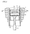
- a known oilless reciprocating air compressor will be described.
- a cylinder head 4 is mounted via a sucking valve plate 2 and a spacer 3.
- the cylinder head 4 is separated into a suction chamber 6 and a discharge chamber 7 by a partition wall 5.
- An inlet 8 is formed in the side wall of the suction chamber 6 and an outlet 9 is formed in the side wall of the discharging chamber 7.
- a sucking bore 10 is formed through the bottom of the suction chamber 6, and discharge bores 11,12 are formed through the spacer 3 and the sucking valve plate 2 to communicate with the discharge chamber 7.
- a discharge valve plate 13 is mounted on the spacer 3 at the upper end of the discharge bore 11 and opens to communicate with the discharge chamber 7.
- a hard alumite layer 14 is formed on the inner surface of the cylinder 1, and an Al alloy piston 15 is slidably fitted in the cylinder 1.
- a piston pin 16 which radially extends in the piston 15 is connected to a crankshaft 18 via a connecting rod 17.
- An annular groove 19 is formed on the piston 15 and a resin piston ring 20 is fitted in the annular groove 19 to move slightly.
- crankshaft 18 is rotated to allow the piston 15 to reciprocate via the connecting rod 17, so that air sucked through the inlet 8 and the sucking bore 10 is compressed and discharged through the discharge bore 12,11 and the outlet 9.
- a number of small resin pieces 20a peeled off the outer surface of the resin piston ring 20 come into a gap between the resin piston ring 20 and the lower surface of the piston-ring groove 19 to form an air path therebetween.
- leakage occurs through the space to decrease compression efficiency and to cause noise.
- sealing capability of the resin piston ring 20 becomes poor to decrease discharge performance of the oilless reciprocating air compressor. Furthermore leakage is likely to generate abnormal sound. High temperature air on a compression chamber thermally gives adverse effects to a bearing of the piston, thereby decreasing the lives of the piston pin 16, the end of the connecting rod 17 and the bearing.
- the piston ring In high-pressure and high-temperature operation, the piston ring is abnormally worn to decrease sealing capability and is then worn locally to breakage. To prevent abnormal sound during operation and prevent the life of the bearing from reducing owing to heat by leaked high-temperature compressed air, the piston ring has to be replaced at an earlier stage.
- one or more labyrinth grooves are formed on the upper and lower surfaces of the annular groove, and small pieces of worn piston ring are introduced into the labyrinth grooves to keep piston-ring function for a long time. A gas leaked along the bottom surface of the piston ring is decreased owing to labyrinth action of the annular groove.
- the inventor of the present invention thought that a layer different from Al might be formed to obtain no minute bores in the inner surface of the cylinder.
- Metal plating such as Ni or Cr is applied to the inner surface of the cylinder, but coating of Ni and Cr decreases sliding performance and seizure resistance. Especially in high-pressure and high-temperature operation, it does not improve the life of the piston ring.
- an object of the invention to provide an oilless reciprocating air compressor operable at high-pressure and high-temperature of 2 to 3 MPa over 1 MPa to prevent generation of small resin pieces from a piston ring which slidably reciprocates in a cylinder to keep sealing capapility of the piston ring for a long time, to prevent abnormal sounds caused by leakage and to prevent heat from transmitting to a bearing of a piston, further avoiding damages or fauling during reciprocation of the piston ring or piston to greatly extend the life of the piston ring to keep its performance for a long time.
- An oilless reciprocating air compressor according to the present invention provides structural features as below:
- Material Composite material of polytetrafluoroethylene resin (TeflonTM) and graphite Features: tension strength 13 to 35 MPa, compression strength 10 to 13 MPa, Vickers hardness: Hv 360 to 400
- COPNA resin of which the piston is made is a thermosetting resin prepared by crosslinking a polycyclic aromatic hydrocarbon, such as naphthalene, anthracene, phenanthrene, pyrene or coal tar pitch, by paraxylene glycol in the presence of an acid catalyst.
- COPNA is an abbreviation of "condensed polynuclear aromatic” and is known in U.S. Patent No.5,605,401.
- Graphite in both the piston and the piston ring has heat resistance and increases sliding performance. Teflon of the piston ring provides self-lubricating property.
- the inner surface of a cylinder 1 made of Al or Al alloy is worked and a SiC coating 21 is formed on the inner surface.
- the minimum thickness of the coating is advantageous for manufacturing cost.
- the life of a resin piston ring 20 requires more than ten thousand hours and its thickness thus requires more than 10 ⁇ m as initial wear is 2 to 3 ⁇ m. Accordingly the thickness is determined to 15 ⁇ m.
- the thickness of the coating 21 may be more than 0.5 ⁇ m.
- the SiC coating is 0.5 ⁇ m thick at minimum, and 50 to 100 ⁇ m thick at maximum.
- the surface is ground to allow average surface roughness Ra to be 0.05 to 0.5 ⁇ m.
- SiC contained in the SiC coating 21 comprise minute ceramic particles having diameter of less than 1 ⁇ m, so that high-hardness dense flat surface layer is formed on the inner surface of the cylinder 1. Therefore, coefficient of friction is decreased to improve sliding performance and wear resistance is greatly increased, thereby increasing the life of the piston ring 20 significantly and facilitating maintenance of an oilless reciprocating air compressor.
- SiC in the coating 21 increases heat-releasing effect.
- the piston ring 20 reciprocates with high lubricating property and reduces sliding resistance. Heat releasing capability of SiC contained in the coating 20 increases the life of the piston ring 20. Furthermore, there is no resin powders 20a separately generated from the piston ring 20 or significantly few compared with the prior art thereby effectively preventing a sliding portion from being damaged.
- the outer surface of the piston ring and the inner surface of the cylinder are both high lubricating property.
- the inner surface of the cylinder is flat and provides high hardness. Owing to heat-releasing effect of the SiC coating, the piston ring is initially worn by about 100 ⁇ m, but thereafter worn very slowly for a long time.
- SiC coating significantly increases the life of the resin piston ring to overcome the foregoing disadvantages not only at low pressure and low temperature but also at high pressure and high temperature.
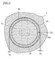
- Fig. 5 shows another embodiment of the present invention
- the thickness "S1" of a right-side SiC coating 21 at a portion to which higher side thrust acts by a piston 15 during operation is slightly greater than the thickness "S2" at the other side.
- a receiving projection 19a in an annular groove 19 is positioned at the thicker SiC coating 21.
- An abutment 22 or a gap between the ends of a piston ring 20 is engaged on the side surfaces of the receiving projection 19a, so that an opening of the abutment 22 is closed by the inner surface of a cylinder.
Landscapes
- Engineering & Computer Science (AREA)
- General Engineering & Computer Science (AREA)
- Mechanical Engineering (AREA)
- Chemical & Material Sciences (AREA)
- Combustion & Propulsion (AREA)
- Compressor (AREA)
- Pistons, Piston Rings, And Cylinders (AREA)
Applications Claiming Priority (2)
| Application Number | Priority Date | Filing Date | Title |
|---|---|---|---|
| JP2004056632 | 2004-03-01 | ||
| JP2004056632A JP2005248729A (ja) | 2004-03-01 | 2004-03-01 | 無給油式往復動空気圧縮機 |
Publications (1)
| Publication Number | Publication Date |
|---|---|
| EP1577553A1 true EP1577553A1 (de) | 2005-09-21 |
Family
ID=34836471
Family Applications (1)
| Application Number | Title | Priority Date | Filing Date |
|---|---|---|---|
| EP05003997A Withdrawn EP1577553A1 (de) | 2004-03-01 | 2005-02-24 | Ölfreier Luftkolbenverdichter |
Country Status (5)
| Country | Link |
|---|---|
| US (1) | US20050188839A1 (de) |
| EP (1) | EP1577553A1 (de) |
| JP (1) | JP2005248729A (de) |
| KR (1) | KR20060043273A (de) |
| CN (1) | CN1664365A (de) |
Cited By (5)
| Publication number | Priority date | Publication date | Assignee | Title |
|---|---|---|---|---|
| ITMI20110959A1 (it) * | 2011-05-27 | 2012-11-28 | Ceme Spa | Elettropompa del tipo a cursore oscillante |
| TWI385306B (de) * | 2009-07-24 | 2013-02-11 | ||
| CN105221392A (zh) * | 2015-10-26 | 2016-01-06 | 珠海格力节能环保制冷技术研究中心有限公司 | 压缩机润滑油注入结构及压缩机 |
| EP2818716A4 (de) * | 2012-02-20 | 2016-05-18 | Panasonic Corp | Gleitelement und kühlkompressor damit, kühlschrank und klimaanlage |
| WO2019072721A1 (de) * | 2017-10-11 | 2019-04-18 | Mahle International Gmbh | Ölfreier kompressor |
Families Citing this family (15)
| Publication number | Priority date | Publication date | Assignee | Title |
|---|---|---|---|---|
| US20060060164A1 (en) * | 2004-09-20 | 2006-03-23 | Gerfast Sten R | Internal combustion engine without oil |
| JP5026689B2 (ja) * | 2005-11-17 | 2012-09-12 | 株式会社日立産機システム | 往復動圧縮機 |
| KR100755945B1 (ko) | 2006-04-28 | 2007-09-06 | 주식회사코핸즈 | 반급유식 오일레스 공기압축기 |
| US8359967B2 (en) * | 2006-09-29 | 2013-01-29 | Schlumberger Technology Corporation | Fluid end reinforced with a composite material |
| JP2008237516A (ja) * | 2007-03-27 | 2008-10-09 | Topcon Corp | 非接触式眼圧計のエアー噴射装置 |
| US9856866B2 (en) | 2011-01-28 | 2018-01-02 | Wabtec Holding Corp. | Oil-free air compressor for rail vehicles |
| JP5967227B2 (ja) * | 2013-01-31 | 2016-08-10 | 株式会社豊田自動織機 | 圧縮機 |
| SG11201603955UA (en) * | 2013-12-26 | 2016-07-28 | Hitachi Ind Equipment Sys | Piston ring and compressor using the same |
| JP6090303B2 (ja) * | 2014-12-24 | 2017-03-08 | マツダ株式会社 | エンジン |
| WO2018016130A1 (ja) * | 2016-07-19 | 2018-01-25 | Tpr株式会社 | 内燃機関の製造方法、内燃機関および連結シリンダ |
| CN106523320B (zh) * | 2017-01-13 | 2018-08-17 | 厦门闳图盛道科技有限公司 | 一种低能耗的无油静音空压机 |
| JP6563441B2 (ja) * | 2017-06-26 | 2019-08-21 | 株式会社不二工機 | パイロット式電磁弁 |
| CN112594153B (zh) * | 2020-12-16 | 2023-08-15 | 浙江凯途机电有限公司 | 一种节能气体无油压缩机及其多级压缩结构 |
| US20250180117A1 (en) * | 2022-03-24 | 2025-06-05 | Kabushiki Kaisha Riken | Sliding mechanism |
| TWI883830B (zh) * | 2024-02-21 | 2025-05-11 | 已久工業股份有限公司 | 空壓機 |
Citations (3)
| Publication number | Priority date | Publication date | Assignee | Title |
|---|---|---|---|---|
| GB1074018A (en) * | 1963-08-20 | 1967-06-28 | Erdoelchemie Gmbh | Porous metals |
| JPS58183881A (ja) * | 1982-04-19 | 1983-10-27 | Matsushita Electric Ind Co Ltd | 圧縮機 |
| US5117742A (en) * | 1989-04-28 | 1992-06-02 | Iwata Air Compressor Mfg. Co. Ltd. | Piston of composite material with c-shaped ring groove |
Family Cites Families (3)
| Publication number | Priority date | Publication date | Assignee | Title |
|---|---|---|---|---|
| JPH08184321A (ja) * | 1994-10-31 | 1996-07-16 | Ntn Corp | 転がり軸受 |
| JPH10169557A (ja) * | 1996-12-06 | 1998-06-23 | Toyota Autom Loom Works Ltd | 圧縮機 |
| WO1998055783A1 (de) * | 1997-06-02 | 1998-12-10 | Maschinenfabrik Sulzer-Burckhardt Ag | Dichtelement für trockenlaufsysteme und verwendung eines solchen dichtelements |
-
2004
- 2004-03-01 JP JP2004056632A patent/JP2005248729A/ja active Pending
-
2005
- 2005-02-24 EP EP05003997A patent/EP1577553A1/de not_active Withdrawn
- 2005-02-25 CN CN2005100089459A patent/CN1664365A/zh active Pending
- 2005-02-28 KR KR1020050016752A patent/KR20060043273A/ko not_active Ceased
- 2005-03-01 US US11/069,371 patent/US20050188839A1/en not_active Abandoned
Patent Citations (3)
| Publication number | Priority date | Publication date | Assignee | Title |
|---|---|---|---|---|
| GB1074018A (en) * | 1963-08-20 | 1967-06-28 | Erdoelchemie Gmbh | Porous metals |
| JPS58183881A (ja) * | 1982-04-19 | 1983-10-27 | Matsushita Electric Ind Co Ltd | 圧縮機 |
| US5117742A (en) * | 1989-04-28 | 1992-06-02 | Iwata Air Compressor Mfg. Co. Ltd. | Piston of composite material with c-shaped ring groove |
Non-Patent Citations (1)
| Title |
|---|
| PATENT ABSTRACTS OF JAPAN vol. 008, no. 026 (M - 273) 3 February 1984 (1984-02-03) * |
Cited By (9)
| Publication number | Priority date | Publication date | Assignee | Title |
|---|---|---|---|---|
| TWI385306B (de) * | 2009-07-24 | 2013-02-11 | ||
| ITMI20110959A1 (it) * | 2011-05-27 | 2012-11-28 | Ceme Spa | Elettropompa del tipo a cursore oscillante |
| EP2818716A4 (de) * | 2012-02-20 | 2016-05-18 | Panasonic Corp | Gleitelement und kühlkompressor damit, kühlschrank und klimaanlage |
| EP3176436A1 (de) * | 2012-02-20 | 2017-06-07 | Panasonic Corporation | Gleitelement, kältemittelverdichter mit gleitelement, kühlschrank und klimaanlage |
| EP3176435A1 (de) * | 2012-02-20 | 2017-06-07 | Panasonic Corporation | Gleitelement, kältemittelverdichter mit gleitelement, kühlschrank und klimaanlage |
| US10704541B2 (en) | 2012-02-20 | 2020-07-07 | Panasonic Intellectual Property Management Co., Ltd. | Slide member, refrigerant compressor incorporating slide member, refrigerator and air conditioner |
| CN105221392A (zh) * | 2015-10-26 | 2016-01-06 | 珠海格力节能环保制冷技术研究中心有限公司 | 压缩机润滑油注入结构及压缩机 |
| CN105221392B (zh) * | 2015-10-26 | 2017-09-19 | 珠海格力节能环保制冷技术研究中心有限公司 | 压缩机润滑油注入结构及压缩机 |
| WO2019072721A1 (de) * | 2017-10-11 | 2019-04-18 | Mahle International Gmbh | Ölfreier kompressor |
Also Published As
| Publication number | Publication date |
|---|---|
| JP2005248729A (ja) | 2005-09-15 |
| US20050188839A1 (en) | 2005-09-01 |
| KR20060043273A (ko) | 2006-05-15 |
| CN1664365A (zh) | 2005-09-07 |
Similar Documents
| Publication | Publication Date | Title |
|---|---|---|
| EP1577553A1 (de) | Ölfreier Luftkolbenverdichter | |
| KR100711455B1 (ko) | 압축장치 | |
| US20240159231A1 (en) | Composite structures for reciprocating gas compressor systems | |
| JP2003138287A (ja) | 摺動材および摺動装置 | |
| US7140291B2 (en) | Oil-free/oil-less air compressor with an improved seal | |
| CN111502991B (zh) | 旋转压缩机及其滑片组件和制冷循环系统 | |
| US7510195B2 (en) | High temperature and high pressure compressor piston ring | |
| US20030096134A1 (en) | Sliding member for compressor | |
| US5007331A (en) | Dry run-high pressure stage of a multistage piston compressor | |
| KR0155456B1 (ko) | 로터리 압축기 | |
| WO2020250743A1 (ja) | 摺動材 | |
| US7004061B2 (en) | Swash-plate compressor having a special sliding surface between a coupling portion of a piston and a shoe | |
| JP5026689B2 (ja) | 往復動圧縮機 | |
| JP3114874B2 (ja) | ピストンリングをもつ圧縮機用ピストン | |
| CN115405515A (zh) | 一种超高压、高频往复运动柱塞泵的密封组合结构 | |
| CN107091233B (zh) | 旋转式压缩机 | |
| JPH10148178A (ja) | 往復動圧縮機 | |
| JP2003206860A (ja) | 往復動圧縮機およびそれに用いるピストン,ピストンリング,張りリングならびにディスタンスリング | |
| RU234997U1 (ru) | Шатун коленчатого вала | |
| JP2000045945A (ja) | 往復動圧縮機 | |
| KR102850879B1 (ko) | 미끄럼 이동 부재 및 유체 기계 | |
| JP2009133231A (ja) | 無給油式真空ポンプ | |
| JPH04262077A (ja) | 往復動圧縮機 | |
| JP2010019091A (ja) | 斜板式圧縮機 | |
| JPS6348845Y2 (de) |
Legal Events
| Date | Code | Title | Description |
|---|---|---|---|
| PUAI | Public reference made under article 153(3) epc to a published international application that has entered the european phase |
Free format text: ORIGINAL CODE: 0009012 |
|
| 17P | Request for examination filed |
Effective date: 20050224 |
|
| AK | Designated contracting states |
Kind code of ref document: A1 Designated state(s): AT BE BG CH CY CZ DE DK EE ES FI FR GB GR HU IE IS IT LI LT LU MC NL PL PT RO SE SI SK TR |
|
| AX | Request for extension of the european patent |
Extension state: AL BA HR LV MK YU |
|
| AKX | Designation fees paid |
Designated state(s): DE IT |
|
| STAA | Information on the status of an ep patent application or granted ep patent |
Free format text: STATUS: THE APPLICATION IS DEEMED TO BE WITHDRAWN |
|
| 18D | Application deemed to be withdrawn |
Effective date: 20060728 |