EP1577208B1 - Motorrad - Google Patents
Motorrad Download PDFInfo
- Publication number
- EP1577208B1 EP1577208B1 EP05006160A EP05006160A EP1577208B1 EP 1577208 B1 EP1577208 B1 EP 1577208B1 EP 05006160 A EP05006160 A EP 05006160A EP 05006160 A EP05006160 A EP 05006160A EP 1577208 B1 EP1577208 B1 EP 1577208B1
- Authority
- EP
- European Patent Office
- Prior art keywords
- muffler
- heat
- type vehicle
- riding type
- saddle riding
- Prior art date
- Legal status (The legal status is an assumption and is not a legal conclusion. Google has not performed a legal analysis and makes no representation as to the accuracy of the status listed.)
- Expired - Lifetime
Links
Images


Classifications
-
- B—PERFORMING OPERATIONS; TRANSPORTING
- B62—LAND VEHICLES FOR TRAVELLING OTHERWISE THAN ON RAILS
- B62K—CYCLES; CYCLE FRAMES; CYCLE STEERING DEVICES; RIDER-OPERATED TERMINAL CONTROLS SPECIALLY ADAPTED FOR CYCLES; CYCLE AXLE SUSPENSIONS; CYCLE SIDECARS, FORECARS, OR THE LIKE
- B62K11/00—Motorcycles, engine-assisted cycles or motor scooters with one or two wheels
-
- B—PERFORMING OPERATIONS; TRANSPORTING
- B62—LAND VEHICLES FOR TRAVELLING OTHERWISE THAN ON RAILS
- B62K—CYCLES; CYCLE FRAMES; CYCLE STEERING DEVICES; RIDER-OPERATED TERMINAL CONTROLS SPECIALLY ADAPTED FOR CYCLES; CYCLE AXLE SUSPENSIONS; CYCLE SIDECARS, FORECARS, OR THE LIKE
- B62K19/00—Cycle frames
- B62K19/30—Frame parts shaped to receive other cycle parts or accessories
-
- B—PERFORMING OPERATIONS; TRANSPORTING
- B62—LAND VEHICLES FOR TRAVELLING OTHERWISE THAN ON RAILS
- B62M—RIDER PROPULSION OF WHEELED VEHICLES OR SLEDGES; POWERED PROPULSION OF SLEDGES OR SINGLE-TRACK CYCLES; TRANSMISSIONS SPECIALLY ADAPTED FOR SUCH VEHICLES
- B62M7/00—Motorcycles characterised by position of motor or engine
- B62M7/02—Motorcycles characterised by position of motor or engine with engine between front and rear wheels
-
- F—MECHANICAL ENGINEERING; LIGHTING; HEATING; WEAPONS; BLASTING
- F01—MACHINES OR ENGINES IN GENERAL; ENGINE PLANTS IN GENERAL; STEAM ENGINES
- F01N—GAS-FLOW SILENCERS OR EXHAUST APPARATUS FOR MACHINES OR ENGINES IN GENERAL; GAS-FLOW SILENCERS OR EXHAUST APPARATUS FOR INTERNAL-COMBUSTION ENGINES
- F01N13/00—Exhaust or silencing apparatus characterised by constructional features
- F01N13/04—Exhaust or silencing apparatus characterised by constructional features having two or more silencers in parallel, e.g. having interconnections for multi-cylinder engines
-
- F—MECHANICAL ENGINEERING; LIGHTING; HEATING; WEAPONS; BLASTING
- F01—MACHINES OR ENGINES IN GENERAL; ENGINE PLANTS IN GENERAL; STEAM ENGINES
- F01N—GAS-FLOW SILENCERS OR EXHAUST APPARATUS FOR MACHINES OR ENGINES IN GENERAL; GAS-FLOW SILENCERS OR EXHAUST APPARATUS FOR INTERNAL-COMBUSTION ENGINES
- F01N13/00—Exhaust or silencing apparatus characterised by constructional features
- F01N13/08—Other arrangements or adaptations of exhaust conduits
-
- F—MECHANICAL ENGINEERING; LIGHTING; HEATING; WEAPONS; BLASTING
- F01—MACHINES OR ENGINES IN GENERAL; ENGINE PLANTS IN GENERAL; STEAM ENGINES
- F01N—GAS-FLOW SILENCERS OR EXHAUST APPARATUS FOR MACHINES OR ENGINES IN GENERAL; GAS-FLOW SILENCERS OR EXHAUST APPARATUS FOR INTERNAL-COMBUSTION ENGINES
- F01N13/00—Exhaust or silencing apparatus characterised by constructional features
- F01N13/14—Exhaust or silencing apparatus characterised by constructional features having thermal insulation
-
- F—MECHANICAL ENGINEERING; LIGHTING; HEATING; WEAPONS; BLASTING
- F01—MACHINES OR ENGINES IN GENERAL; ENGINE PLANTS IN GENERAL; STEAM ENGINES
- F01N—GAS-FLOW SILENCERS OR EXHAUST APPARATUS FOR MACHINES OR ENGINES IN GENERAL; GAS-FLOW SILENCERS OR EXHAUST APPARATUS FOR INTERNAL-COMBUSTION ENGINES
- F01N13/00—Exhaust or silencing apparatus characterised by constructional features
- F01N13/18—Construction facilitating manufacture, assembly, or disassembly
- F01N13/1805—Fixing exhaust manifolds, exhaust pipes or pipe sections to each other, to engine or to vehicle body
-
- F—MECHANICAL ENGINEERING; LIGHTING; HEATING; WEAPONS; BLASTING
- F01—MACHINES OR ENGINES IN GENERAL; ENGINE PLANTS IN GENERAL; STEAM ENGINES
- F01N—GAS-FLOW SILENCERS OR EXHAUST APPARATUS FOR MACHINES OR ENGINES IN GENERAL; GAS-FLOW SILENCERS OR EXHAUST APPARATUS FOR INTERNAL-COMBUSTION ENGINES
- F01N3/00—Exhaust or silencing apparatus having means for purifying, rendering innocuous, or otherwise treating exhaust
- F01N3/02—Exhaust or silencing apparatus having means for purifying, rendering innocuous, or otherwise treating exhaust for cooling, or for removing solid constituents of, exhaust
- F01N3/05—Exhaust or silencing apparatus having means for purifying, rendering innocuous, or otherwise treating exhaust for cooling, or for removing solid constituents of, exhaust by means of air, e.g. by mixing exhaust with air
-
- F—MECHANICAL ENGINEERING; LIGHTING; HEATING; WEAPONS; BLASTING
- F01—MACHINES OR ENGINES IN GENERAL; ENGINE PLANTS IN GENERAL; STEAM ENGINES
- F01N—GAS-FLOW SILENCERS OR EXHAUST APPARATUS FOR MACHINES OR ENGINES IN GENERAL; GAS-FLOW SILENCERS OR EXHAUST APPARATUS FOR INTERNAL-COMBUSTION ENGINES
- F01N2340/00—Dimensional characteristics of the exhaust system, e.g. length, diameter or volume of the exhaust apparatus; Spatial arrangements of exhaust apparatuses
- F01N2340/04—Arrangement of the exhaust system relative to a vehicle or parts thereof
-
- F—MECHANICAL ENGINEERING; LIGHTING; HEATING; WEAPONS; BLASTING
- F01—MACHINES OR ENGINES IN GENERAL; ENGINE PLANTS IN GENERAL; STEAM ENGINES
- F01N—GAS-FLOW SILENCERS OR EXHAUST APPARATUS FOR MACHINES OR ENGINES IN GENERAL; GAS-FLOW SILENCERS OR EXHAUST APPARATUS FOR INTERNAL-COMBUSTION ENGINES
- F01N2590/00—Exhaust or silencing apparatus adapted to particular use, e.g. for military applications, airplanes, submarines
- F01N2590/04—Exhaust or silencing apparatus adapted to particular use, e.g. for military applications, airplanes, submarines for motorcycles
-
- Y—GENERAL TAGGING OF NEW TECHNOLOGICAL DEVELOPMENTS; GENERAL TAGGING OF CROSS-SECTIONAL TECHNOLOGIES SPANNING OVER SEVERAL SECTIONS OF THE IPC; TECHNICAL SUBJECTS COVERED BY FORMER USPC CROSS-REFERENCE ART COLLECTIONS [XRACs] AND DIGESTS
- Y02—TECHNOLOGIES OR APPLICATIONS FOR MITIGATION OR ADAPTATION AGAINST CLIMATE CHANGE
- Y02T—CLIMATE CHANGE MITIGATION TECHNOLOGIES RELATED TO TRANSPORTATION
- Y02T10/00—Road transport of goods or passengers
- Y02T10/10—Internal combustion engine [ICE] based vehicles
- Y02T10/12—Improving ICE efficiencies
Definitions
- the invention relates to a saddle riding type vehicle according to the preamble of independent claim 1.
- Such saddle riding type vehicle can be taken from prior art document US 5,183130 .
- said document teaches a muffler body surrounded by an air guide cover.
- a cooling chamber allowing flow of cooling air is defined between the outer surface of the muffler body and the inner surface of the air guide cover.
- Said air guide cover is formed at its rear end portion with an air outlet opening downwardly directed to the outside.
- the length of the respective passages defined between the muffler body and the air guide cover are different depending on the location of the respective passage.
- the air that flows around the muffler body is heated up in a non-uniform manner, so that air discharged from the air outlet at the rear end of the cover may have different temperature values, such that there would be a risk of creating undesired hot spots.
- an object of the invention to provide an improved saddle riding type vehicle capable of effectively insulating heat existing between a muffler and a cowl.
- a seat for placement of a rider of the saddle riding type vehicle is installed above the rear wheel, and/or in that the muffler is substantially cylindrical, and/or in that the muffler and/or the exhaust pipe extend obliquely upwardly towards a rear portion of the vehicle, and/or in that the heat discharge device is provided capable of discharging heat towards the rear wheel.
- the body frame includes a rear frame which is installed above the rear wheel, the muffler is arranged outside the rear frame in a widthwise direction of the vehicle, wherein preferably the heat discharge device is disposed in a space which is surrounded by the muffler, the rear wheel and/or the rear frame.
- the heat discharge device comprises a case and a fan unit, wherein preferably a bottom wall of the case has a discharge opening through which the heat discharged out of the heat insulation space by the fan unit is dischargeable out of the case.
- the muffler comprises a plurality of mufflers, wherein preferably a rear frame of the vehicle is installed between the plurality of mufflers.
- the fan unit is installed below a center of an exhaust outlet of the muffler, through which exhaust gas of the engine is dischargeable to the outside.
- the cover member has an outside air suction port through which outside air is introduceable into the heat insulation space and an air discharge port which communicates with the heat discharge device and/or in that the cover member has at least one projection which projects into the heat insulation space, wherein preferably the projection is installed adjacent to the air discharge port.
- the case comprises an upper case part and a lower case part which is coupled to the upper case part, wherein preferably the upper case part has a suction opening which communicates with the heat insulation space, and/or wherein the lower case part as the discharge opening.
- the fan unit comprises a fan and an electric motor for rotating the fan, wherein, preferably, the electric motor is fastened to the rear frame by an electric motor fastening member, wherein, further preferably, the electric motor fastening member has an opening at a position which corresponds to the suction opening.
- a catalyst for purifying exhaust gas of the engine is installed between the engine and the muffler, preferably closer to the engine than to an air discharge port of the muffler.
- the cover member is made of a resin material and/or in that the cover member comprises an outer cover part which externally covers the muffler in a widthwise direction of the vehicle, and/or an inner cover part which is positioned between a rear frame of the vehicle and the muffler, wherein, preferably, a heat insulation material for insulating heat of the muffler is provided in the heat insulation space.
- a heat insulation sheet for insulating heat of the muffler is installed on an inner surface of the cover member, in particular adjacent to the air discharge port and/or in that the body frame has an outer surface which has a plate-shaped contour when viewed in the widthwise direction of the vehicle.
- a rear frame of the vehicle has a narrow width part which has a width less than that of the body frame, wherein preferably the muffler is installed outside the narrow width part in the widthwise direction of the vehicle.
- a rear frame of the vehicle has a horizontal plate part which is substantially parallel to a rotation axis of the rear wheel and/or has a side wall part which extends substantially vertically from an edge of the horizontal plate part, wherein preferably a portion of the side wall part which is connected to the body frame has a height greater than that of the other portion of the side wall part.
- a rear frame of the vehicle is connected to the body frame by a locking member, wherein preferably the locking member is covered by the cover member.
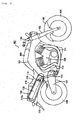
- Fig. 1 is a side view illustrating main component elements of a saddle riding type vehicle in accordance with a first embodiment of the present invention.
- Fig. 2 is a schematic view taken by viewing the saddle riding type vehicle shown in Fig. 1 from the rear.
- Fig. 3 is schematically sectional views illustrating several component elements of the saddle riding type vehicle shown in Fig. 1 .
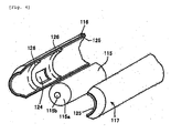
- Fig. 4 is a perspective view illustrating a part of the saddle riding type vehicle shown in Fig. 1 .
- the reference symbol MC designates a saddle riding type vehicle on which a rider can ride by outstretching legs.
- the saddle riding type vehicle comprises a body frame 101, a front fork 102 rotatably mounted to a front end of the body frame 101, and a front fender 103 installed on a portion of the front fork 102.
- a front wheel (tire) 104 is rotatably mounted to a lower end of the front fork 102, and a steering handle 105 is mounted to an upper end of the front fork 102.
- a 'V'-shaped two-cylinder air-cooling type engine (heat resistant engine) 106 is installed below the body frame 101.
- a swing arm 107 is pivotably mounted to a lower rear end of the body frame 101, and a rear wheel (tire) 108 is rotatably mounted to a distal end of the swing arm 107.
- a fuel tank 109 is installed on the body frame 101, and a seat 110 is installed to extend from the fuel tank 109 installed on the body frame 101 toward a position above the rear wheel 108.
- a muffler (silencer) 115 is connected to a rear end 114 of a rear exhaust pipe 113 which extends rearward from the joining part 112 (only one rear exhaust pipe 113 is illustrated).
- a cover member (cowl) 100 which has a cylindrical configuration surrounds a circumferential outer surface of the muffler 115.
- the cover member 100 comprises a semi-cylindrical fender 116 and a semi-cylindrical side cover 117.
- a rear frame 118 is installed to be connected to the body frame 101 below the seat 110 and above the rear wheel 108.
- a pair of mufflers 115 are installed at both sides of the rear frame 118.
- the heat discharge device (a cooling device) 120 is disposed in a space which is surrounded by a rear fender 119 extending from the rear frame 118 above the rear wheel 108, a pair of mufflers 115, the rear wheel 108 and the rear frame 118.
- the heat discharge device 120 is securely held with respect to the rear frame 118 by a holding member which extends through the cover member 100.
- the heat discharge device 120 is connected to a heat insulation space 123 which is defined between the muffler 115 and the cover member 100.
- the heat discharge device 120 functions to discharge air existing in the heat insulation space 123 to the outside and to cool the heat generated by the rearward embedded type muffler 115.
- the cover member 100 has an air suction port 122 through which air is introduced into the heat insulation space 123 and an air discharge port 124. Due to this fact, the air existing in the heat insulation space 123 can be effectively discharged to the outside.
- a heat insulation sheet 125 is installed on a circumferential inner surface of the cover member 100 at least adjacent to the air discharge port 124 to insulate heat generated adjacent to the air discharge port 124.
- Ribs 126 are projectedly formed on the circumferential inner surface of the cover member 100 adjacent to the air discharge port 124.
- a catalyst 130 is installed on a circumferential inner surface of the muffler 115 upstream of the air discharge port 124 of the heat insulation space 123.
- the catalyst 130 is composed of ceramic which is coated with noble metal such as platinum, palladium, rhodium, etc. and a filter.
- the catalyst 130 functions to cause a chemical reaction of hydrocarbon (HC) contained in unburned gas and bum noxious carbon monoxide in the muffler 115. Therefore, it is possible to efficiently purify exhaust gas.
- HC hydrocarbon
- a muffler cap 115a is installed at an exhaust outlet 115b of the muffler 115.
- the pair of left and right mufflers 115 is respectively connected to the ends 114 of the rear exhaust pipes 113.
- the pair of left and right mufflers 115 is located at both sides of the seat (tandem seat) 110 for a driver and a rider which are placed above the rear wheel 108, and slopingly extend rearwards and upwards.
- the heat discharge device 120 is installed in a space (which is not employed in the conventional art) which is defined in a rear part of the saddle riding type vehicle and is delimited by the left and right mufflers 115, the rear wheel 108 supported by the pivotable swing arm 107 (at an uppermost position when the rear wheel 108 is moved upward and downward), and the rear frame 118. For this reason, the air of a high temperature which exists in the heat insulation space 123 can be efficiently discharged to the outside through the space while not deteriorating an outer appearance of the saddle riding type vehicle.
- the heat discharge device 120 comprises a case 120c which includes an upper cover 120a and a lower cover 120b coupled to the upper cover 120a, and a fan unit 121 which is accommodated in the case 120c.
- the upper cover 120a has a suction opening 120a1 which communicates with the heat insulation space 123
- a bottom wall of the lower cover 120b has a discharge opening 120b1 which is opposite to the seat 110 and through which the air sucked from the heat insulation space 123 by the fan unit 121 can be discharged to the outside.
- the fan unit 121 is located below a center of the exhaust outlet 115b which is defined at a rear end of the muffler 115. Thus, it is possible to prevent a widthwise size of the saddle riding type vehicle from increasing due to the provision of the fan unit 121.
- the fan unit 121 comprises a fan 121a, a motor 121b for rotating the fan 121a, and a motor fastening part 121c for fastening the motor 121b to the rear frame 118.
- the motor 121b is fastened to the rear frame 118 by the motor fastening part 121 c.
- the motor fastening part 121c has a fan opening 121d at a position which corresponds to the suction opening 120a1 of the upper cover 120a. Hence, the air existing in the heat insulation space 123 can be reliably guided into the case 120c.
- the fan unit 121 comprises an electric fan unit wherein the fan 121a is rotated by the motor 121b which employs a battery as its power source. Through the rotation of the fan 121a, a low pressure zone is created adjacent to the discharge opening 120b1 which is defined in the bottom wall of the lower cover 120b. Accordingly, the air sucked through the air suction port 122 (see Fig.
- the warmed-up air sequentially passes through the air discharge port 124 which is defined through the fender 116 and the suction opening 120a1 of the upper cover 120a of the heat discharge device 120 and is discharged toward the rear wheel 108 through the discharge opening 120b1 which is defined through the bottom wall of the lower cover 120b (and faces the ground).
- At least one additional suction opening for introducing air into the heat insulation space 123 may be defined through a wall of the side cover 117.
- a louver capable of changing an air flowing direction may be installed in the discharge opening 120b1 of the lower cover 120b, as a result of which warmed-up air can be efficiently discharged to a space between the fender 116 and the rear wheel 108.
- the fender 116 and the side cover 117 constitute the cover member 100 having a cylindrical configuration and surround the circumferential outer surface of the muffler 115.
- the heat insulation sheet 125 (having a thickness of 0.1-4 mm) is attached to the inner surfaces of the fender 116 and the side cover 117 adjacent to the air discharge port 124 (see Fig. 3 ).
- the heat insulation sheet 125 may be attached only to the inner surface of the fender 116.
- the air discharge port 124 defined through each of the left and right fenders 116 communicates with the suction opening 120a1 defined through the upper cover 120a of the heat discharge device 120.
- the low pressure zone is created adjacent to the discharge opening 120b1 by the fan unit (a cooling fan unit) 121, by which air flow is created in the heat insulation space 123 defined between the muffler 115 and the cover member 100. Consequently, as the heated air is discharged toward the rear wheel 108 through the discharge opening 120b1 defined in the lower cover 120b, the heated air is prevented from being transferred to the rider.
- the fan unit 121 of the heat discharge device 120 is attached to the rear frame 118 at a region (a fan space) adjacent to the rear wheel 108 in a space which is delimited by a horizontal axis 121c1 passing through centers of the exhaust outlets 115b (tail pipes) of the left and right muffler caps 115a and vertical axes 121d1 and 121 d2 respectively passing through the centers of the exhaust outlets 115b of the left and right muffler caps 115a.
- a pair of electric fans may be installed adjacent to the pair of suction openings 120a1, respectively.
- the pair of electric fans may be installed adjacent to the pair of suction openings 120a1, respectively.
- the air discharge port 124 defined through each of the left and right fenders 116 vertically passes through the horizontal axis 121c1 which is defined by a line connecting the centers of the exhaust outlets 115b of the left and right muffler caps 115a and has a predetermined vertical length.
- the air flowing passage (of a thickness of about 15 mm) for efficient flow of air from the front end of the muffler 115 toward the rear end of the muffler 115 is defined in the heat insulation space 123 defined between the muffler 115 and the cover member 100.
- the ribs 126 are covered with the heat insulation sheet 125.
- the ribs 126 are not necessarily needed, and without the ribs 126, an original purpose of ensuring reliable air flow can be achieved.
- the catalyst 130 is located on a portion of the circumferential outer surface of the muffler 115 which is most likely to be heated (the circumferential outer surface of the muffler 115 reaches a temperature of about 400°C).
- a temperature sensor 127 is installed adjacent to the catalyst 130 (see Fig. 3 ). In response to a signal from the temperature sensor 127, the fan unit 121 is turned on or off and a rotational speed of the fan 121a is controlled.
- the fan unit 121 controls a rotational speed of the fan 121 a in response to a signal from the temperature sensor 127. For example, when a temperature sensed by the temperature sensor 127 is high, a rotational speed of the fan 121a is increased, and when a temperature sensed by the temperature sensor 127 is low, a rotational speed of the fan 121 a is decreased.
- the fan unit 121 may be driven.
- the fan unit 121 installed in the heat discharge device 120 according to the first embodiment, which is installed in the heat discharge device 120, is not limited to the electric fan, and instead, a fan unit employing a hydraulic motor as a driving source, a fan unit driven by exhaust gas, etc. can be adopted.
- the saddle riding type vehicle according to the first embodiment may have a 'V'-shaped four-cylinder engine.
- two pairs of the front exhaust pipes are connected by joining parts, respectively.
- the pair of left and right mufflers 115 the present invention is not limited to the number of mufflers. Therefore, the saddle riding type vehicle may have a single muffler.
- Fig. 5 is a schematic view illustrating a main part of the saddle riding type vehicle according to the second embodiment of the present invention.
- the heat discharge device 120 is located in a space which is surrounded by the mufflers 115, the swing arm 107 and the rear wheel 108.
- the heat discharge device 120 is connected to the heat insulation space 123 which is defined by the exhaust outlet 115b and the cover member 100, and functions to discharge air existing in the heat insulation space 123 to the outside.
- a saddle riding type vehicle comprising a body frame (a body frame 101), a rear wheel (a rear wheel 108) rotatably attached to the body frame, an engine (an engine 106) installed on the body frame, a substantially cylindrical muffler (a muffler 115) connected to an exhaust pipe (a rear exhaust pipe 113) which extends from the engine and obliquely installed rearwards of the rear wheel, and a cover member (a cover member 100) for axially surrounding the muffler, wherein a heat insulation space (a heat insulation space 123) is defined between the muffler and the cover member to insulate heat of the muffler.
- a heat insulation space a heat insulation space 123
- the saddle riding type vehicle can effectively insulate heat existing between the muffler and the cover member.
- the saddle riding type vehicle further comprises a heat discharge device (a heat discharge device 120) communicated with the heat insulation space to discharge heat existing in the heat insulation space out of the heat insulation space.
- a heat discharge device (a heat discharge device 120) communicated with the heat insulation space to discharge heat existing in the heat insulation space out of the heat insulation space.
- a seat (a seat 110) on which a driver of the saddle riding type vehicle sits is installed above the rear wheel, and the heat discharge device discharges heat toward the rear wheel.
- the heat discharge device can discharge heat existing between the muffler and the cover member toward the rear wheel, the saddle riding type vehicle can suppress heat from being transferred to a rider.
- the body frame includes a rear frame (a rear frame 118) which is installed above the rear wheel, the muffler is arranged outside the rear frame in a widthwise direction of the saddle riding type vehicle, and the heat discharge device is disposed in a space which is surrounded by the muffler, the rear wheel and the rear frame.
- a rear frame a rear frame 118
- the heat discharge device is disposed in a space which is surrounded by the muffler, the rear wheel and the rear frame.
- the heat discharge device is disposed in the space which is surrounded by the muffler, the rear wheel and the rear frame, it is possible to prevent an outer appearance of the saddle riding type vehicle from being deteriorated due to the presence of the heat discharge device.
- the heat discharge device comprises a case (a case 120c) and a fan unit (a fan unit 121), and a bottom wall of the case has a discharge opening (a discharge opening 120b1) through which the heat discharged out of the heat insulation space by the fan unit is discharged out of the case.
- the saddle riding type vehicle can suppress heat from being transferred to a rider.
- the muffler comprises a plurality of mufflers, and the rear frame is installed between the plurality of mufflers.
- the rear frame is installed between the plurality of mufflers, it is possible to locate the heat discharge device by efficiently using the space which is surrounded by the plurality of mufflers, the rear wheel and the rear frame.
- the fan unit is installed below a center (a horizontal axis 121c1) of an exhaust outlet (an exhaust outlet 115b) of the muffler, through which exhaust gas of the engine is discharged to the outside.
- the cover member has an outside air suction port (an air suction port 122) through which outside air is introduced into the heat insulation space and an air discharge port (an air discharge port 124) which communicates with the heat discharge device.
- the saddle riding type vehicle can efficiently discharge the heat existing between the muffler and the cover member.
- the cover member has at least one projection (a rib 126) which projects into the heat insulation space, and the projection is installed adjacent to the air discharge port.
- the saddle riding type vehicle can increase an air flow rate between the muffler and the cover member and efficiently discharge the heat existing between the muffler and the cover member.
- the case comprises an upper case part (an upper cover 120a) and a lower case part (a lower cover 120b) which is coupled to the upper case part, the upper case part has a suction opening (a suction opening 120a1) which communicates with the heat insulation space, and the lower case part has a discharge opening (a discharge opening 120b1).
- an upper case part an upper cover 120a
- a lower case part a lower cover 120b
- the upper case part has a suction opening (a suction opening 120a1) which communicates with the heat insulation space
- the lower case part has a discharge opening (a discharge opening 120b1).
- the case comprises the upper case part having the suction opening and the lower case part having the discharge opening, the case can be easily formed.
- the fan unit comprises a fan (a fan 121a) and an electric motor (a motor 121 b) for rotating the fan, and the electric motor is fastened to the rear frame by an electric motor fastening member (a motor fastening part 121 c).
- a fan a fan 121a
- an electric motor a motor 121 b
- the electric motor is fastened to the rear frame by an electric motor fastening member (a motor fastening part 121 c).
- the electric motor fastening member has an opening (a fan opening 121d) at a position which corresponds to the suction opening.
- the saddle riding type vehicle can easily introduce the heat existing between the muffler and the cover member into the case.
- a catalyst for purifying exhaust gas of the engine is installed between the engine and the muffler closer to the engine than the air discharge port.
- the saddle riding type vehicle can efficiently purify the exhaust gas.
Landscapes
- Engineering & Computer Science (AREA)
- Chemical & Material Sciences (AREA)
- Mechanical Engineering (AREA)
- Combustion & Propulsion (AREA)
- General Engineering & Computer Science (AREA)
- Health & Medical Sciences (AREA)
- Chemical Kinetics & Catalysis (AREA)
- Toxicology (AREA)
- Transportation (AREA)
- Automatic Cycles, And Cycles In General (AREA)
- Exhaust Silencers (AREA)
- Axle Suspensions And Sidecars For Cycles (AREA)
Claims (10)
- Fahrzeug vom Spreizsitz- Typ, aufweisend:einen Karosserierahmen (101, 208), ein Hinterrad (108, 211), drehbar mit dem Karosserierahmen (101, 208) verbunden,eine Brennkraftmaschine (106, 210), installiert an dem Karosserierahmen (101, 208),einen Schalldämpfer (115, 220, 220), verbunden mit dem Abgasrohr (113, 213), der sich von der Brennkraftmaschine (106, 210) in eine Richtung nach hinten erstreckt,wobei ein Abdeckteil (100, 203), um zumindest teilweise den Schalldämpfer (115, 220) axial zu umgeben, vorgesehen ist, wobei ein wärmeisolierender Raum (123) zwischen dem Schalldämpfer (115, 220) und dem Abdeckteil (100, 203) zum Isolieren einer Wärme des Schalldämpfers (115, 220) gebildet ist,eine Wärmeabgabevorrichtung (120), konfiguriert, um mit dem wärmeisolierenden Raum (123) in Verbindung zu sein und um eine Wärme, die in dem wärmeisolierenden Raum (123) vorhanden ist, nach außerhalb des wärmeisolierenden Raumes (123) abzugeben,
dadurch gekennzeichnet, dassdie Wärmeabgabevorrichtung (120) eine Lüftereinheit (121) in einem Gehäuse (120) aufweist, das eine Auslassöffnung (120b1) hat, durch die die Wärme in Richtung nach außen abgegeben wird, wobei die Lüftereinheit (121) eine Niederdruckzone, benachbart zu der Auslassöffnung (120b1), erzeugt. - Fahrzeug vom Spreizsitz- Typ nach Anspruch 1, dadurch gekennzeichnet, dass ein Sitz (110) zum Platzieren eines Fahrers des Fahrzeuges vom Spreizsitz- Typ oberhalb des Hinterrades (108, 211) installiert ist und / oder dadurch, dass der Schalldämpfer (115, 220) im Wesentlichen zylindrisch ist und / oder dadurch, dass sich der Schalldämpfer (115, 220) und / oder das Abgasrohr (113, 213) schräg nach oben in Richtung zu einer hinteren Position des Fahrzeuges erstrecken und / oder dadurch, dass die Wärmeabgabevorrichtung (120) vorgesehen ist, in der Lage zu sein, Wärme in Richtung zu dem Hinterrad (108, 211) abzugeben.
- Fahrzeug vom Spreizsitz- Typ nach den Ansprüchen 1 und 2, dadurch gekennzeichnet, dass der Karosserierahmen (101, 208) einen hinteren Rahmen (118, 225) enthält, der oberhalb des Hinterrades (108, 211) angeordnet ist, der Schalldämpfer (115, 220) außerhalb des hinteren Rahmens (118, 225) in einer Richtung der Breite des Fahrzeuges angeordnet ist, wobei vorzugsweise die Wärmeabgabevorrichtung (120) in einem Raum angeordnet ist, der durch den Schalldämpfer (115, 220), das Hinterrad (108, 211) und / oder den hinteren Rahmen (118, 225) umgeben ist.
- Fahrzeug vom Spreizsitz- Typ nach zumindest einem der Ansprüche 1 bis 3, dadurch gekennzeichnet, dass die Abgabeöffnung in einer Bodenwand des Gehäuses (120c) angeordnet ist.
- Fahrzeug vom Spreizsitz- Typ nach zumindest einem der Ansprüche 1 bis 4, dadurch gekennzeichnet, dass der Schalldämpfer (115, 220) eine Mehrzahl von Schalldämpfern (115, 220, 115, 220) aufweist, wobei vorzugsweise ein hinterer Rahmen (118, 225) des Fahrzeuges zwischen der Mehrzahl von Schalldämpfern (115, 220, 115, 220) installiert ist.
- Fahrzeug vom Spreizsitz- Typ nach zumindest einem der Ansprüche 1 bis 5, dadurch gekennzeichnet, dass die Lüftereinheit (121) unter einer Mitte eines Abgasauslasses (115, 220b) des Schalldämpfers (115, 220) angeordnet ist, durch die Abgas der Brennkraftmaschine (106, 210) nach außen abgebbar ist.
- Fahrzeug vom Spreizsitz- Typ nach zumindest einem der Ansprüche 1 bis 6, dadurch gekennzeichnet, dass das Abdeckteil (100, 203) eine Außenluft- Ansaugöffnung (122) hat, durch die Außenluft in den wärmeisolierenden Raum (123) einführbar ist, und eine Luftabgabeöffnung (124), die mit der Wärmeabgabevorrichtung (120) in Verbindung ist, und / oder dadurch, dass das Abdeckteil (100, 203) zumindest einen Vorsprung (126) hat, der in den wärmeisolierenden Raum (123) vorspringt, wobei vorzugsweise der Vorsprung (126) benachbart zu der Luftabgabeöffnung (124) installiert ist.
- Fahrzeug vom Spreizsitz- Typ nach zumindest einem der Ansprüche 1 bis 7, dadurch gekennzeichnet, dass das Gehäuse (120c) ein oberes Gehäuseteil (120a) und ein unteres Gehäuseteil (120b), das mit dem oberen Gehäuseteil (120a) gekuppelt ist, aufweist, wobei vorzugsweise das obere Gehäuseteil (120a) eine Ansaugöffnung (120a1) hat, die mit dem wärmeisolierenden Raum (123) in Verbindung ist, und wobei das untere Gehäuseteil (120b) die Abgabeöffnung (120b1) hat.
- Fahrzeug vom Spreizsitz- Typ nach zumindest einem der Ansprüche 1 bis 8, dadurch gekennzeichnet, dass die Lüftereinheit (121) einen Lüfter (121a) und einen Elektromotor (121 b) zum Drehen des Lüfters aufweist, wobei vorzugsweise der Elektromotor (121 b) an dem hinteren Rahmen (118, 225) durch ein Elektromotor - Befestigungsteil (121c) befestigt ist, wobei außerdem vorzugsweise das Elektromotor - Befestigungsteil (121c) eine Öffnung (121d) an einer Position hat, die der Ansaugöffnung entspricht.
- Fahrzeug vom Spreizsitz- Typ nach zumindest einem der Ansprüche 1 bis 9, dadurch gekennzeichnet, dass ein Katalysator (130) zum Reinigen von Abgas der Brennkraftmaschine (106, 210) zwischen der Brennkraftmaschine (106, 210) und dem Schalldämpfer (115, 220), vorzugsweise näher an der Brennkraftmaschine (106, 210) als zu einer Luftabgabeöffnung (124) des Schalldämpfers (115, 220), installiert ist.
Priority Applications (1)
| Application Number | Priority Date | Filing Date | Title |
|---|---|---|---|
| EP07008889A EP1808368A1 (de) | 2004-03-19 | 2005-03-21 | Motorrad |
Applications Claiming Priority (6)
| Application Number | Priority Date | Filing Date | Title |
|---|---|---|---|
| JP2004079599 | 2004-03-19 | ||
| JP2004079599 | 2004-03-19 | ||
| JP2004194550 | 2004-06-30 | ||
| JP2004194550 | 2004-06-30 | ||
| JP2005059651A JP2006044633A (ja) | 2004-03-19 | 2005-03-03 | 鞍乗型車両 |
| JP2005059651 | 2005-03-03 |
Related Child Applications (2)
| Application Number | Title | Priority Date | Filing Date |
|---|---|---|---|
| EP07008889A Division EP1808368A1 (de) | 2004-03-19 | 2005-03-21 | Motorrad |
| EP07008889.3 Division-Into | 2007-05-02 |
Publications (3)
| Publication Number | Publication Date |
|---|---|
| EP1577208A2 EP1577208A2 (de) | 2005-09-21 |
| EP1577208A3 EP1577208A3 (de) | 2007-05-30 |
| EP1577208B1 true EP1577208B1 (de) | 2010-07-28 |
Family
ID=34841539
Family Applications (2)
| Application Number | Title | Priority Date | Filing Date |
|---|---|---|---|
| EP07008889A Withdrawn EP1808368A1 (de) | 2004-03-19 | 2005-03-21 | Motorrad |
| EP05006160A Expired - Lifetime EP1577208B1 (de) | 2004-03-19 | 2005-03-21 | Motorrad |
Family Applications Before (1)
| Application Number | Title | Priority Date | Filing Date |
|---|---|---|---|
| EP07008889A Withdrawn EP1808368A1 (de) | 2004-03-19 | 2005-03-21 | Motorrad |
Country Status (4)
| Country | Link |
|---|---|
| EP (2) | EP1808368A1 (de) |
| JP (1) | JP2006044633A (de) |
| AT (1) | ATE475584T1 (de) |
| DE (1) | DE602005022514D1 (de) |
Families Citing this family (8)
| Publication number | Priority date | Publication date | Assignee | Title |
|---|---|---|---|---|
| JP2006044640A (ja) * | 2004-07-07 | 2006-02-16 | Yamaha Motor Co Ltd | 鞍乗型車両、及び、リヤアーム取付方法 |
| JP4700586B2 (ja) * | 2006-10-06 | 2011-06-15 | 本田技研工業株式会社 | 自動二輪車の排気装置 |
| WO2009084455A1 (ja) * | 2007-12-28 | 2009-07-09 | Yamaha Hatsudoki Kabushiki Kaisha | 自動二輪車 |
| JP5930944B2 (ja) | 2012-11-09 | 2016-06-08 | 本田技研工業株式会社 | 鞍乗り型車両 |
| US11408313B2 (en) * | 2017-03-27 | 2022-08-09 | Honda Motor Co., Ltd. | Exhaust device for internal combustion engine of saddled vehicle |
| JP6648197B2 (ja) * | 2018-06-26 | 2020-02-14 | 本田技研工業株式会社 | 自動二輪車の排気装置 |
| WO2021065787A1 (ja) * | 2019-09-30 | 2021-04-08 | 本田技研工業株式会社 | 鞍乗り型車両の消音器構造 |
| CN117043051B (zh) * | 2021-03-30 | 2026-01-02 | 本田技研工业株式会社 | 鞍乘型车辆 |
Family Cites Families (20)
| Publication number | Priority date | Publication date | Assignee | Title |
|---|---|---|---|---|
| GB2037678A (en) * | 1978-12-18 | 1980-07-16 | Matthews R E | Motor cycles |
| US4323135A (en) * | 1980-03-11 | 1982-04-06 | Yamaha Hatsudoki Kabushiki Kaisha | Structure for supporting a motorcycle engine |
| JPS56135708A (en) * | 1980-03-26 | 1981-10-23 | Yamaha Motor Co Ltd | Exhaust gas purifier for motor bicycle |
| GB2142591B (en) * | 1983-06-25 | 1986-11-12 | Armstrong Competition Motorcyc | Motorcycle rear wheel suspension |
| US4645028A (en) * | 1983-11-10 | 1987-02-24 | Yamaha Hatsudoki Kabushiki Kaisha | Motorcycle having balloon tire |
| US4903483A (en) * | 1988-02-17 | 1990-02-27 | Yamaha Hatsudoki Kabushiki Kaisha | Exhaust system for V-type engine |
| JP2619495B2 (ja) * | 1988-08-24 | 1997-06-11 | 本田技研工業株式会社 | 2サイクルエンジンの排気装置 |
| JP3034535B2 (ja) * | 1989-07-25 | 2000-04-17 | 本田技研工業株式会社 | 自動二輪車のマフラー装置 |
| JP2723311B2 (ja) * | 1989-10-18 | 1998-03-09 | 本田技研工業株式会社 | 鞍乗り型車両における排気装置 |
| JPH03237211A (ja) * | 1990-02-14 | 1991-10-23 | Suzuki Motor Corp | 自動二輪車のマフラ取付け装置 |
| JP2513425Y2 (ja) * | 1990-03-29 | 1996-10-09 | 本田技研工業株式会社 | 自動二輪車における排気系の冷却装置 |
| US5036947A (en) * | 1990-05-21 | 1991-08-06 | Metzger Jeffrey S | Exhaust pipe shield |
| JPH0577776A (ja) * | 1991-09-18 | 1993-03-30 | Honda Motor Co Ltd | 自動二輪車の物入れ |
| JP3249563B2 (ja) * | 1991-12-27 | 2002-01-21 | ヤマハ発動機株式会社 | 自動二輪車用後輪懸架装置の緩衝ばね配置構造 |
| JP3342254B2 (ja) * | 1995-09-07 | 2002-11-05 | ヤマハ発動機株式会社 | 自動二輪車のリヤサスペンション |
| JP4266245B2 (ja) * | 1998-05-29 | 2009-05-20 | ヤマハ発動機株式会社 | 自動二輪車の駆動装置 |
| JP2003002277A (ja) * | 2001-06-27 | 2003-01-08 | Yamaha Motor Co Ltd | 電動式動力ユニット、電動車両および電動二輪車 |
| JP3578738B2 (ja) * | 2001-08-10 | 2004-10-20 | 本田技研工業株式会社 | 自動2輪車の車体構造 |
| JP2004098884A (ja) * | 2002-09-10 | 2004-04-02 | Honda Motor Co Ltd | 自動二輪車の後部構造 |
| JP2006044640A (ja) * | 2004-07-07 | 2006-02-16 | Yamaha Motor Co Ltd | 鞍乗型車両、及び、リヤアーム取付方法 |
-
2005
- 2005-03-03 JP JP2005059651A patent/JP2006044633A/ja not_active Withdrawn
- 2005-03-21 EP EP07008889A patent/EP1808368A1/de not_active Withdrawn
- 2005-03-21 EP EP05006160A patent/EP1577208B1/de not_active Expired - Lifetime
- 2005-03-21 AT AT05006160T patent/ATE475584T1/de not_active IP Right Cessation
- 2005-03-21 DE DE602005022514T patent/DE602005022514D1/de not_active Expired - Lifetime
Also Published As
| Publication number | Publication date |
|---|---|
| EP1577208A3 (de) | 2007-05-30 |
| EP1808368A1 (de) | 2007-07-18 |
| EP1577208A2 (de) | 2005-09-21 |
| ATE475584T1 (de) | 2010-08-15 |
| DE602005022514D1 (de) | 2010-09-09 |
| JP2006044633A (ja) | 2006-02-16 |
Similar Documents
| Publication | Publication Date | Title |
|---|---|---|
| JP4586438B2 (ja) | 不整地走行車両の前部構造 | |
| JP4139142B2 (ja) | 自動二輪車及びそのエア管理システム | |
| US7399029B2 (en) | System for discharging exhaust air from a radiator in a straddle type vehicle | |
| JP3791897B2 (ja) | スクータ型車両における車体前部の導風構造 | |
| EP2832985B1 (de) | Luftreinigervorrichtung für Fahrzeug | |
| CN106661981A (zh) | 车辆和单缸四冲程发动机单元 | |
| EP2371694A1 (de) | Sattelfahrzeug | |
| EP2159393B1 (de) | Abgasreinigungsvorrichtung für ein Motorrad und mit einer solchen Abgasreinigungsvorrichtung ausgestattetes Motorrad | |
| US7484361B2 (en) | Exhaust gas purifying apparatus of motorcycle | |
| US6102149A (en) | Wind deflecting device in a vehicle including a motorcycle | |
| JP2007038708A (ja) | 揺動三輪車 | |
| EP1577208A2 (de) | Motorrad | |
| EP3524501B1 (de) | Sattelfahrzeug | |
| JP6658820B2 (ja) | 自動二輪車 | |
| WO2003095293A1 (fr) | Radiateur pour vehicule a moteur a deux roues | |
| JP4851890B2 (ja) | 自動二輪車の排気装置 | |
| EP3561246B1 (de) | Grätschsitzfahrzeug | |
| EP2436582B1 (de) | Grätschsitzfahrzeug | |
| WO1991005944A1 (fr) | Dispositif d'echappement pour vehicules du type a selle | |
| BRPI0804627B1 (pt) | Sistema de tratamento de gás de descarga, unidade de motor incluindo o sistema, e veículo incluindo a unidade de motor | |
| JPH06171568A (ja) | 自動2輪車のエンジン冷却装置 | |
| JPH0710060A (ja) | 自動二輪車の冷却装置 | |
| EP4545764B1 (de) | Motor | |
| JP6795681B2 (ja) | 鞍乗り型車両 | |
| JP7751726B2 (ja) | 鞍乗型車両 |
Legal Events
| Date | Code | Title | Description |
|---|---|---|---|
| PUAI | Public reference made under article 153(3) epc to a published international application that has entered the european phase |
Free format text: ORIGINAL CODE: 0009012 |
|
| AK | Designated contracting states |
Kind code of ref document: A2 Designated state(s): AT BE BG CH CY CZ DE DK EE ES FI FR GB GR HU IE IS IT LI LT LU MC NL PL PT RO SE SI SK TR |
|
| AX | Request for extension of the european patent |
Extension state: AL BA HR LV MK YU |
|
| PUAL | Search report despatched |
Free format text: ORIGINAL CODE: 0009013 |
|
| AK | Designated contracting states |
Kind code of ref document: A3 Designated state(s): AT BE BG CH CY CZ DE DK EE ES FI FR GB GR HU IE IS IT LI LT LU MC NL PL PT RO SE SI SK TR |
|
| AX | Request for extension of the european patent |
Extension state: AL BA HR LV MK YU |
|
| RIC1 | Information provided on ipc code assigned before grant |
Ipc: F01N 7/08 20060101ALI20070423BHEP Ipc: B62M 7/02 20060101AFI20050422BHEP Ipc: B62J 17/00 20060101ALI20070423BHEP Ipc: F01N 7/14 20060101ALI20070423BHEP |
|
| 17P | Request for examination filed |
Effective date: 20070510 |
|
| 17Q | First examination report despatched |
Effective date: 20070709 |
|
| AKX | Designation fees paid |
Designated state(s): AT BE BG CH CY CZ DE DK EE ES FI FR GB GR HU IE IS IT LI LT LU MC NL PL PT RO SE SI SK TR |
|
| GRAP | Despatch of communication of intention to grant a patent |
Free format text: ORIGINAL CODE: EPIDOSNIGR1 |
|
| GRAC | Information related to communication of intention to grant a patent modified |
Free format text: ORIGINAL CODE: EPIDOSCIGR1 |
|
| RIN1 | Information on inventor provided before grant (corrected) |
Inventor name: KIKUHARA, HIROSHI Inventor name: KAWASE, MASAO |
|
| GRAS | Grant fee paid |
Free format text: ORIGINAL CODE: EPIDOSNIGR3 |
|
| GRAA | (expected) grant |
Free format text: ORIGINAL CODE: 0009210 |
|
| AK | Designated contracting states |
Kind code of ref document: B1 Designated state(s): AT BE BG CH CY CZ DE DK EE ES FI FR GB GR HU IE IS IT LI LT LU MC NL PL PT RO SE SI SK TR |
|
| REG | Reference to a national code |
Ref country code: GB Ref legal event code: FG4D |
|
| REG | Reference to a national code |
Ref country code: CH Ref legal event code: EP |
|
| REG | Reference to a national code |
Ref country code: IE Ref legal event code: FG4D |
|
| REF | Corresponds to: |
Ref document number: 602005022514 Country of ref document: DE Date of ref document: 20100909 Kind code of ref document: P |
|
| REG | Reference to a national code |
Ref country code: NL Ref legal event code: VDEP Effective date: 20100728 |
|
| LTIE | Lt: invalidation of european patent or patent extension |
Effective date: 20100728 |
|
| PG25 | Lapsed in a contracting state [announced via postgrant information from national office to epo] |
Ref country code: AT Free format text: LAPSE BECAUSE OF FAILURE TO SUBMIT A TRANSLATION OF THE DESCRIPTION OR TO PAY THE FEE WITHIN THE PRESCRIBED TIME-LIMIT Effective date: 20100728 Ref country code: NL Free format text: LAPSE BECAUSE OF FAILURE TO SUBMIT A TRANSLATION OF THE DESCRIPTION OR TO PAY THE FEE WITHIN THE PRESCRIBED TIME-LIMIT Effective date: 20100728 Ref country code: LT Free format text: LAPSE BECAUSE OF FAILURE TO SUBMIT A TRANSLATION OF THE DESCRIPTION OR TO PAY THE FEE WITHIN THE PRESCRIBED TIME-LIMIT Effective date: 20100728 Ref country code: FI Free format text: LAPSE BECAUSE OF FAILURE TO SUBMIT A TRANSLATION OF THE DESCRIPTION OR TO PAY THE FEE WITHIN THE PRESCRIBED TIME-LIMIT Effective date: 20100728 |
|
| PG25 | Lapsed in a contracting state [announced via postgrant information from national office to epo] |
Ref country code: BG Free format text: LAPSE BECAUSE OF FAILURE TO SUBMIT A TRANSLATION OF THE DESCRIPTION OR TO PAY THE FEE WITHIN THE PRESCRIBED TIME-LIMIT Effective date: 20101028 Ref country code: CY Free format text: LAPSE BECAUSE OF FAILURE TO SUBMIT A TRANSLATION OF THE DESCRIPTION OR TO PAY THE FEE WITHIN THE PRESCRIBED TIME-LIMIT Effective date: 20100728 Ref country code: IS Free format text: LAPSE BECAUSE OF FAILURE TO SUBMIT A TRANSLATION OF THE DESCRIPTION OR TO PAY THE FEE WITHIN THE PRESCRIBED TIME-LIMIT Effective date: 20101128 Ref country code: PL Free format text: LAPSE BECAUSE OF FAILURE TO SUBMIT A TRANSLATION OF THE DESCRIPTION OR TO PAY THE FEE WITHIN THE PRESCRIBED TIME-LIMIT Effective date: 20100728 Ref country code: PT Free format text: LAPSE BECAUSE OF FAILURE TO SUBMIT A TRANSLATION OF THE DESCRIPTION OR TO PAY THE FEE WITHIN THE PRESCRIBED TIME-LIMIT Effective date: 20101129 Ref country code: SI Free format text: LAPSE BECAUSE OF FAILURE TO SUBMIT A TRANSLATION OF THE DESCRIPTION OR TO PAY THE FEE WITHIN THE PRESCRIBED TIME-LIMIT Effective date: 20100728 |
|
| PG25 | Lapsed in a contracting state [announced via postgrant information from national office to epo] |
Ref country code: GR Free format text: LAPSE BECAUSE OF FAILURE TO SUBMIT A TRANSLATION OF THE DESCRIPTION OR TO PAY THE FEE WITHIN THE PRESCRIBED TIME-LIMIT Effective date: 20101029 Ref country code: BE Free format text: LAPSE BECAUSE OF FAILURE TO SUBMIT A TRANSLATION OF THE DESCRIPTION OR TO PAY THE FEE WITHIN THE PRESCRIBED TIME-LIMIT Effective date: 20100728 Ref country code: SE Free format text: LAPSE BECAUSE OF FAILURE TO SUBMIT A TRANSLATION OF THE DESCRIPTION OR TO PAY THE FEE WITHIN THE PRESCRIBED TIME-LIMIT Effective date: 20100728 |
|
| PG25 | Lapsed in a contracting state [announced via postgrant information from national office to epo] |
Ref country code: DK Free format text: LAPSE BECAUSE OF FAILURE TO SUBMIT A TRANSLATION OF THE DESCRIPTION OR TO PAY THE FEE WITHIN THE PRESCRIBED TIME-LIMIT Effective date: 20100728 |
|
| PG25 | Lapsed in a contracting state [announced via postgrant information from national office to epo] |
Ref country code: IT Free format text: LAPSE BECAUSE OF FAILURE TO SUBMIT A TRANSLATION OF THE DESCRIPTION OR TO PAY THE FEE WITHIN THE PRESCRIBED TIME-LIMIT Effective date: 20100728 Ref country code: CZ Free format text: LAPSE BECAUSE OF FAILURE TO SUBMIT A TRANSLATION OF THE DESCRIPTION OR TO PAY THE FEE WITHIN THE PRESCRIBED TIME-LIMIT Effective date: 20100728 Ref country code: EE Free format text: LAPSE BECAUSE OF FAILURE TO SUBMIT A TRANSLATION OF THE DESCRIPTION OR TO PAY THE FEE WITHIN THE PRESCRIBED TIME-LIMIT Effective date: 20100728 Ref country code: SK Free format text: LAPSE BECAUSE OF FAILURE TO SUBMIT A TRANSLATION OF THE DESCRIPTION OR TO PAY THE FEE WITHIN THE PRESCRIBED TIME-LIMIT Effective date: 20100728 Ref country code: RO Free format text: LAPSE BECAUSE OF FAILURE TO SUBMIT A TRANSLATION OF THE DESCRIPTION OR TO PAY THE FEE WITHIN THE PRESCRIBED TIME-LIMIT Effective date: 20100728 |
|
| PLBE | No opposition filed within time limit |
Free format text: ORIGINAL CODE: 0009261 |
|
| STAA | Information on the status of an ep patent application or granted ep patent |
Free format text: STATUS: NO OPPOSITION FILED WITHIN TIME LIMIT |
|
| PG25 | Lapsed in a contracting state [announced via postgrant information from national office to epo] |
Ref country code: ES Free format text: LAPSE BECAUSE OF FAILURE TO SUBMIT A TRANSLATION OF THE DESCRIPTION OR TO PAY THE FEE WITHIN THE PRESCRIBED TIME-LIMIT Effective date: 20101108 |
|
| 26N | No opposition filed |
Effective date: 20110429 |
|
| REG | Reference to a national code |
Ref country code: DE Ref legal event code: R097 Ref document number: 602005022514 Country of ref document: DE Effective date: 20110429 |
|
| PG25 | Lapsed in a contracting state [announced via postgrant information from national office to epo] |
Ref country code: MC Free format text: LAPSE BECAUSE OF NON-PAYMENT OF DUE FEES Effective date: 20110331 |
|
| REG | Reference to a national code |
Ref country code: CH Ref legal event code: PL |
|
| REG | Reference to a national code |
Ref country code: IE Ref legal event code: MM4A |
|
| PG25 | Lapsed in a contracting state [announced via postgrant information from national office to epo] |
Ref country code: LI Free format text: LAPSE BECAUSE OF NON-PAYMENT OF DUE FEES Effective date: 20110331 Ref country code: CH Free format text: LAPSE BECAUSE OF NON-PAYMENT OF DUE FEES Effective date: 20110331 Ref country code: IE Free format text: LAPSE BECAUSE OF NON-PAYMENT OF DUE FEES Effective date: 20110321 |
|
| PG25 | Lapsed in a contracting state [announced via postgrant information from national office to epo] |
Ref country code: LU Free format text: LAPSE BECAUSE OF NON-PAYMENT OF DUE FEES Effective date: 20110321 |
|
| PG25 | Lapsed in a contracting state [announced via postgrant information from national office to epo] |
Ref country code: TR Free format text: LAPSE BECAUSE OF FAILURE TO SUBMIT A TRANSLATION OF THE DESCRIPTION OR TO PAY THE FEE WITHIN THE PRESCRIBED TIME-LIMIT Effective date: 20100728 |
|
| PG25 | Lapsed in a contracting state [announced via postgrant information from national office to epo] |
Ref country code: HU Free format text: LAPSE BECAUSE OF FAILURE TO SUBMIT A TRANSLATION OF THE DESCRIPTION OR TO PAY THE FEE WITHIN THE PRESCRIBED TIME-LIMIT Effective date: 20100728 |
|
| REG | Reference to a national code |
Ref country code: FR Ref legal event code: PLFP Year of fee payment: 12 |
|
| REG | Reference to a national code |
Ref country code: FR Ref legal event code: PLFP Year of fee payment: 13 |
|
| REG | Reference to a national code |
Ref country code: FR Ref legal event code: PLFP Year of fee payment: 14 |
|
| PGFP | Annual fee paid to national office [announced via postgrant information from national office to epo] |
Ref country code: FR Payment date: 20210323 Year of fee payment: 17 |
|
| PGFP | Annual fee paid to national office [announced via postgrant information from national office to epo] |
Ref country code: DE Payment date: 20210319 Year of fee payment: 17 Ref country code: GB Payment date: 20210324 Year of fee payment: 17 |
|
| REG | Reference to a national code |
Ref country code: DE Ref legal event code: R119 Ref document number: 602005022514 Country of ref document: DE |
|
| GBPC | Gb: european patent ceased through non-payment of renewal fee |
Effective date: 20220321 |
|
| PG25 | Lapsed in a contracting state [announced via postgrant information from national office to epo] |
Ref country code: GB Free format text: LAPSE BECAUSE OF NON-PAYMENT OF DUE FEES Effective date: 20220321 Ref country code: FR Free format text: LAPSE BECAUSE OF NON-PAYMENT OF DUE FEES Effective date: 20220331 Ref country code: DE Free format text: LAPSE BECAUSE OF NON-PAYMENT OF DUE FEES Effective date: 20221001 |