EP1577066B1 - Schneidblatt- und Motorträger mit Höhe/Winkel-Einstellvorrichtung - Google Patents
Schneidblatt- und Motorträger mit Höhe/Winkel-Einstellvorrichtung Download PDFInfo
- Publication number
- EP1577066B1 EP1577066B1 EP05010597A EP05010597A EP1577066B1 EP 1577066 B1 EP1577066 B1 EP 1577066B1 EP 05010597 A EP05010597 A EP 05010597A EP 05010597 A EP05010597 A EP 05010597A EP 1577066 B1 EP1577066 B1 EP 1577066B1
- Authority
- EP
- European Patent Office
- Prior art keywords
- support plate
- cutting tool
- work table
- pivot
- bracket
- Prior art date
- Legal status (The legal status is an assumption and is not a legal conclusion. Google has not performed a legal analysis and makes no representation as to the accuracy of the status listed.)
- Expired - Lifetime
Links
Images


Classifications
-
- B—PERFORMING OPERATIONS; TRANSPORTING
- B27—WORKING OR PRESERVING WOOD OR SIMILAR MATERIAL; NAILING OR STAPLING MACHINES IN GENERAL
- B27B—SAWS FOR WOOD OR SIMILAR MATERIAL; COMPONENTS OR ACCESSORIES THEREFOR
- B27B5/00—Sawing machines working with circular or cylindrical saw blades; Components or equipment therefor
- B27B5/16—Saw benches
- B27B5/22—Saw benches with non-feedable circular saw blade
- B27B5/24—Saw benches with non-feedable circular saw blade the saw blade being adjustable according to depth or angle of cut
- B27B5/243—Saw benches with non-feedable circular saw blade the saw blade being adjustable according to depth or angle of cut the saw blade being arranged underneath the work-table
-
- B—PERFORMING OPERATIONS; TRANSPORTING
- B23—MACHINE TOOLS; METAL-WORKING NOT OTHERWISE PROVIDED FOR
- B23D—PLANING; SLOTTING; SHEARING; BROACHING; SAWING; FILING; SCRAPING; LIKE OPERATIONS FOR WORKING METAL BY REMOVING MATERIAL, NOT OTHERWISE PROVIDED FOR
- B23D45/00—Sawing machines or sawing devices with circular saw blades or with friction saw discs
- B23D45/06—Sawing machines or sawing devices with circular saw blades or with friction saw discs with a circular saw blade arranged underneath a stationary work-table
- B23D45/061—Sawing machines or sawing devices with circular saw blades or with friction saw discs with a circular saw blade arranged underneath a stationary work-table the saw blade being mounted on a carriage
- B23D45/062—Sawing machines or sawing devices with circular saw blades or with friction saw discs with a circular saw blade arranged underneath a stationary work-table the saw blade being mounted on a carriage the saw blade being adjustable according to depth or angle of cut
-
- B—PERFORMING OPERATIONS; TRANSPORTING
- B23—MACHINE TOOLS; METAL-WORKING NOT OTHERWISE PROVIDED FOR
- B23D—PLANING; SLOTTING; SHEARING; BROACHING; SAWING; FILING; SCRAPING; LIKE OPERATIONS FOR WORKING METAL BY REMOVING MATERIAL, NOT OTHERWISE PROVIDED FOR
- B23D45/00—Sawing machines or sawing devices with circular saw blades or with friction saw discs
- B23D45/06—Sawing machines or sawing devices with circular saw blades or with friction saw discs with a circular saw blade arranged underneath a stationary work-table
- B23D45/065—Sawing machines or sawing devices with circular saw blades or with friction saw discs with a circular saw blade arranged underneath a stationary work-table with the saw blade carried by a pivoted lever
- B23D45/067—Sawing machines or sawing devices with circular saw blades or with friction saw discs with a circular saw blade arranged underneath a stationary work-table with the saw blade carried by a pivoted lever the saw blade being adjustable according to depth or angle of cut
-
- B—PERFORMING OPERATIONS; TRANSPORTING
- B23—MACHINE TOOLS; METAL-WORKING NOT OTHERWISE PROVIDED FOR
- B23D—PLANING; SLOTTING; SHEARING; BROACHING; SAWING; FILING; SCRAPING; LIKE OPERATIONS FOR WORKING METAL BY REMOVING MATERIAL, NOT OTHERWISE PROVIDED FOR
- B23D45/00—Sawing machines or sawing devices with circular saw blades or with friction saw discs
- B23D45/06—Sawing machines or sawing devices with circular saw blades or with friction saw discs with a circular saw blade arranged underneath a stationary work-table
- B23D45/068—Sawing machines or sawing devices with circular saw blades or with friction saw discs with a circular saw blade arranged underneath a stationary work-table the saw blade being adjustable according to depth or angle of cut
-
- B—PERFORMING OPERATIONS; TRANSPORTING
- B23—MACHINE TOOLS; METAL-WORKING NOT OTHERWISE PROVIDED FOR
- B23D—PLANING; SLOTTING; SHEARING; BROACHING; SAWING; FILING; SCRAPING; LIKE OPERATIONS FOR WORKING METAL BY REMOVING MATERIAL, NOT OTHERWISE PROVIDED FOR
- B23D47/00—Sawing machines or sawing devices working with circular saw blades, characterised only by constructional features of particular parts
- B23D47/02—Sawing machines or sawing devices working with circular saw blades, characterised only by constructional features of particular parts of frames; of guiding arrangements for work-table or saw-carrier
-
- B—PERFORMING OPERATIONS; TRANSPORTING
- B27—WORKING OR PRESERVING WOOD OR SIMILAR MATERIAL; NAILING OR STAPLING MACHINES IN GENERAL
- B27B—SAWS FOR WOOD OR SIMILAR MATERIAL; COMPONENTS OR ACCESSORIES THEREFOR
- B27B5/00—Sawing machines working with circular or cylindrical saw blades; Components or equipment therefor
- B27B5/29—Details; Component parts; Accessories
- B27B5/38—Devices for braking the circular saw blade or the saw spindle; Devices for damping vibrations of the circular saw blade, e.g. silencing
-
- Y—GENERAL TAGGING OF NEW TECHNOLOGICAL DEVELOPMENTS; GENERAL TAGGING OF CROSS-SECTIONAL TECHNOLOGIES SPANNING OVER SEVERAL SECTIONS OF THE IPC; TECHNICAL SUBJECTS COVERED BY FORMER USPC CROSS-REFERENCE ART COLLECTIONS [XRACs] AND DIGESTS
- Y10—TECHNICAL SUBJECTS COVERED BY FORMER USPC
- Y10S—TECHNICAL SUBJECTS COVERED BY FORMER USPC CROSS-REFERENCE ART COLLECTIONS [XRACs] AND DIGESTS
- Y10S83/00—Cutting
- Y10S83/01—Safety devices
-
- Y—GENERAL TAGGING OF NEW TECHNOLOGICAL DEVELOPMENTS; GENERAL TAGGING OF CROSS-SECTIONAL TECHNOLOGIES SPANNING OVER SEVERAL SECTIONS OF THE IPC; TECHNICAL SUBJECTS COVERED BY FORMER USPC CROSS-REFERENCE ART COLLECTIONS [XRACs] AND DIGESTS
- Y10—TECHNICAL SUBJECTS COVERED BY FORMER USPC
- Y10S—TECHNICAL SUBJECTS COVERED BY FORMER USPC CROSS-REFERENCE ART COLLECTIONS [XRACs] AND DIGESTS
- Y10S83/00—Cutting
- Y10S83/954—Knife changing
-
- Y—GENERAL TAGGING OF NEW TECHNOLOGICAL DEVELOPMENTS; GENERAL TAGGING OF CROSS-SECTIONAL TECHNOLOGIES SPANNING OVER SEVERAL SECTIONS OF THE IPC; TECHNICAL SUBJECTS COVERED BY FORMER USPC CROSS-REFERENCE ART COLLECTIONS [XRACs] AND DIGESTS
- Y10—TECHNICAL SUBJECTS COVERED BY FORMER USPC
- Y10T—TECHNICAL SUBJECTS COVERED BY FORMER US CLASSIFICATION
- Y10T83/00—Cutting
- Y10T83/04—Processes
- Y10T83/05—With reorientation of tool between cuts
-
- Y—GENERAL TAGGING OF NEW TECHNOLOGICAL DEVELOPMENTS; GENERAL TAGGING OF CROSS-SECTIONAL TECHNOLOGIES SPANNING OVER SEVERAL SECTIONS OF THE IPC; TECHNICAL SUBJECTS COVERED BY FORMER USPC CROSS-REFERENCE ART COLLECTIONS [XRACs] AND DIGESTS
- Y10—TECHNICAL SUBJECTS COVERED BY FORMER USPC
- Y10T—TECHNICAL SUBJECTS COVERED BY FORMER US CLASSIFICATION
- Y10T83/00—Cutting
- Y10T83/768—Rotatable disc tool pair or tool and carrier
- Y10T83/7684—With means to support work relative to tool[s]
- Y10T83/7701—Supporting surface and tool axis angularly related
- Y10T83/7705—Adjustable angular relationship
-
- Y—GENERAL TAGGING OF NEW TECHNOLOGICAL DEVELOPMENTS; GENERAL TAGGING OF CROSS-SECTIONAL TECHNOLOGIES SPANNING OVER SEVERAL SECTIONS OF THE IPC; TECHNICAL SUBJECTS COVERED BY FORMER USPC CROSS-REFERENCE ART COLLECTIONS [XRACs] AND DIGESTS
- Y10—TECHNICAL SUBJECTS COVERED BY FORMER USPC
- Y10T—TECHNICAL SUBJECTS COVERED BY FORMER US CLASSIFICATION
- Y10T83/00—Cutting
- Y10T83/768—Rotatable disc tool pair or tool and carrier
- Y10T83/7684—With means to support work relative to tool[s]
- Y10T83/7722—Support and tool relatively adjustable
- Y10T83/7726—By movement of the tool
-
- Y—GENERAL TAGGING OF NEW TECHNOLOGICAL DEVELOPMENTS; GENERAL TAGGING OF CROSS-SECTIONAL TECHNOLOGIES SPANNING OVER SEVERAL SECTIONS OF THE IPC; TECHNICAL SUBJECTS COVERED BY FORMER USPC CROSS-REFERENCE ART COLLECTIONS [XRACs] AND DIGESTS
- Y10—TECHNICAL SUBJECTS COVERED BY FORMER USPC
- Y10T—TECHNICAL SUBJECTS COVERED BY FORMER US CLASSIFICATION
- Y10T83/00—Cutting
- Y10T83/768—Rotatable disc tool pair or tool and carrier
- Y10T83/7684—With means to support work relative to tool[s]
- Y10T83/773—Work-support includes passageway for tool [e.g., slotted table]
-
- Y—GENERAL TAGGING OF NEW TECHNOLOGICAL DEVELOPMENTS; GENERAL TAGGING OF CROSS-SECTIONAL TECHNOLOGIES SPANNING OVER SEVERAL SECTIONS OF THE IPC; TECHNICAL SUBJECTS COVERED BY FORMER USPC CROSS-REFERENCE ART COLLECTIONS [XRACs] AND DIGESTS
- Y10—TECHNICAL SUBJECTS COVERED BY FORMER USPC
- Y10T—TECHNICAL SUBJECTS COVERED BY FORMER US CLASSIFICATION
- Y10T83/00—Cutting
- Y10T83/768—Rotatable disc tool pair or tool and carrier
- Y10T83/7747—With means to permit replacement of tool
-
- Y—GENERAL TAGGING OF NEW TECHNOLOGICAL DEVELOPMENTS; GENERAL TAGGING OF CROSS-SECTIONAL TECHNOLOGIES SPANNING OVER SEVERAL SECTIONS OF THE IPC; TECHNICAL SUBJECTS COVERED BY FORMER USPC CROSS-REFERENCE ART COLLECTIONS [XRACs] AND DIGESTS
- Y10—TECHNICAL SUBJECTS COVERED BY FORMER USPC
- Y10T—TECHNICAL SUBJECTS COVERED BY FORMER US CLASSIFICATION
- Y10T83/00—Cutting
- Y10T83/768—Rotatable disc tool pair or tool and carrier
- Y10T83/7793—Means to rotate or oscillate tool
-
- Y—GENERAL TAGGING OF NEW TECHNOLOGICAL DEVELOPMENTS; GENERAL TAGGING OF CROSS-SECTIONAL TECHNOLOGIES SPANNING OVER SEVERAL SECTIONS OF THE IPC; TECHNICAL SUBJECTS COVERED BY FORMER USPC CROSS-REFERENCE ART COLLECTIONS [XRACs] AND DIGESTS
- Y10—TECHNICAL SUBJECTS COVERED BY FORMER USPC
- Y10T—TECHNICAL SUBJECTS COVERED BY FORMER US CLASSIFICATION
- Y10T83/00—Cutting
- Y10T83/869—Means to drive or to guide tool
- Y10T83/8776—Constantly urged tool or tool support [e.g., spring biased]
-
- Y—GENERAL TAGGING OF NEW TECHNOLOGICAL DEVELOPMENTS; GENERAL TAGGING OF CROSS-SECTIONAL TECHNOLOGIES SPANNING OVER SEVERAL SECTIONS OF THE IPC; TECHNICAL SUBJECTS COVERED BY FORMER USPC CROSS-REFERENCE ART COLLECTIONS [XRACs] AND DIGESTS
- Y10—TECHNICAL SUBJECTS COVERED BY FORMER USPC
- Y10T—TECHNICAL SUBJECTS COVERED BY FORMER US CLASSIFICATION
- Y10T83/00—Cutting
- Y10T83/929—Tool or tool with support
- Y10T83/9372—Rotatable type
- Y10T83/9377—Mounting of tool about rod-type shaft
- Y10T83/9379—At end of shaft
-
- Y—GENERAL TAGGING OF NEW TECHNOLOGICAL DEVELOPMENTS; GENERAL TAGGING OF CROSS-SECTIONAL TECHNOLOGIES SPANNING OVER SEVERAL SECTIONS OF THE IPC; TECHNICAL SUBJECTS COVERED BY FORMER USPC CROSS-REFERENCE ART COLLECTIONS [XRACs] AND DIGESTS
- Y10—TECHNICAL SUBJECTS COVERED BY FORMER USPC
- Y10T—TECHNICAL SUBJECTS COVERED BY FORMER US CLASSIFICATION
- Y10T83/00—Cutting
- Y10T83/929—Tool or tool with support
- Y10T83/9457—Joint or connection
- Y10T83/9461—Resiliently biased connection
-
- Y—GENERAL TAGGING OF NEW TECHNOLOGICAL DEVELOPMENTS; GENERAL TAGGING OF CROSS-SECTIONAL TECHNOLOGIES SPANNING OVER SEVERAL SECTIONS OF THE IPC; TECHNICAL SUBJECTS COVERED BY FORMER USPC CROSS-REFERENCE ART COLLECTIONS [XRACs] AND DIGESTS
- Y10—TECHNICAL SUBJECTS COVERED BY FORMER USPC
- Y10T—TECHNICAL SUBJECTS COVERED BY FORMER US CLASSIFICATION
- Y10T83/00—Cutting
- Y10T83/929—Tool or tool with support
- Y10T83/9457—Joint or connection
- Y10T83/9464—For rotary tool
- Y10T83/9469—Adjustable
- Y10T83/9471—Rectilinearly
Definitions
- the present invention relates to a height/angle adjustment mechanism for a saw blade. More particularly, the present invention relates to a motor carrier for a table saw which provides a height/angle adjustment mechanism for a saw blade attached to the powered shaft of the motor.
- a typical table saw includes a base which supports a generally flat table top having a longitudinally extending slot and a pair of side rails extending along opposite sides of the table top generally perpendicular to the slot.
- the side rails are utilised for mounting a rip fence assembly to assist in positioning an article to be cut in relation to a cutting tool.
- a motor is mounted beneath the table top and the cutting tool, which may be a circular saw blade, is mounted for rotation with the powered output shaft of the motor.
- the cutting tool is mounted directly to the shaft of the motor, or if the cutting tool is mounted to a transmission powered by the motor, the mounting of the motor and/or transmission is provided with adjustments which selectively position the cutting tool to extend through the slot in the table top.
- One adjustment for the motor and/or transmission determines the amount of the cutting tool which extends through the slot to control the depth of cutting.
- Another adjustment for the motor and/or transmission determines the angle of the cutting tool with respect to the table top to control the bevel angle or the angle of cutting.
- the cutting tool is thus positioned to project upwardly through the slot and is rotated by the motor with both the height of the cutting tool with respect to the table top and the angle of the cutting tool with respect to the table top being determined by the mounting mechanism for the motor and/or transmission.
- Cutting of the workpiece is normally accomplished by moving the workpiece longitudinally through the rotating cutting tool.
- Machine tools are used for cross cutting (transverse cutting to the length of the workpiece), mitre cutting (at an angle to the length of the workpiece) and rip cutting (longitudinal cutting along the length of the workpiece).
- cross cutting and mitre cutting an angularly and laterally adjustable fixture or fence is used which positions the workpiece perpendicular to or at the desired angle relative to the cutting tool.
- rip cutting a separate rip fence assembly is mounted on the side rails and positioned at a pre-selected distance from the cutting tool in order to perform the longitudinal or rip cutting operation on the workpiece.
- US2852047 describes a tilting and elevating mechanism for a disc type table saw.
- a circular saw blade is mounted on an arbor which is supported by elevating and tilting mechanism.
- Tilting mechanism comprises a U-shaped stamping having arcuately shaped trunnions and which are supported by trunnion cradles shaped as arcuate slots in order to allow the U-shaped stamping to tilt from side to side to enable the circular saw to pivot about a bevel axis.
- a locking means is provided to lock the U-shaped stamping to the saw frame when a desired blade bevel angle has been selected.
- the cutting tool is provided with a height and angle adjustment mechanism.
- the mechanism includes a motor and arbor support plate which is pivotably secured to the bottom of the work surface of the cutting tool by a pair of brackets to provide for the angular adjustment.
- a transmission or gear case is slidably connected to the support plate to provide for the height adjustment.
- the motor, arbor and cutting tool are attached to the gear case.
- the cutting tool height is adjusted by way of a crank and a threaded rod, upon which a rod follower is movably threaded.
- the rod follower is connected to a height adjusting lever for slidably moving the gear case and thus the motor, arbor and cutting tool upwardly and downwardly depending upon the direction in which the crank is rotated.
- the cutting tool angular position is adjusted by pivotably moving the support plate to change the angle of the blade.
- the angular position of the support plate is locked in position by a locking bar which extends through an arcuate slot in the front of the cutting tool base across the support plate and through a similar arcuate slot in a bracket attached to the rear of the cutting tool base.
- a cam lever mechanism is positioned outward of the front of the cutting tool base such that when the cam lever is pivoted to its locked position, the locking bar is pulled forwardly compressing and frictionally locking the support plate between the bracket and the front of the cutting tool base.
- the flexibility of the locking rod and the bracket provides the ability for the compressing of the support plate.
- the locking of the support plate to both the front and rear of the base provides increased rigidity to the system once it is locked.
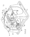
- FIG. 1 a machine tool which is designated generally by the reference numeral 10 incorporating a height/angle adjustment mechanism for the cutting tool and motor carrier in accordance with the present invention. While the height/angle adjustment mechanism of the present invention is being illustrated for exemplary purposes as being used in conjunction with machine tool 10 in the form of a table saw, it is within the scope of the present invention to incorporate the height/angle adjustment mechanism of the present invention into any type of machine tool which utilises a cutting tool.
- machine tool 10 comprises a base 12 which supports a generally rectangular work table 14 defining a working surface 16.
- Work table 14 includes a throat plate 18 which includes an elongated slot 20 through which a circular saw blade 22 protrudes.
- Saw blade 22 is capable to being adjusted for angularity with respect to working surface 16 by an angle or bevel adjustment mechanism 24 as well as being capable of being adjusted for depth of cut by a height adjustment mechanism 26.
- Machine tool 10 is illustrated as a portable table saw which is easily movable from one job site to another. Table saw 10 can easily be picked up and carried utilising work table 14 as the supporting locations when it becomes necessary to lift and carry table saw 10 from one job site to another.
- table saw 10 is illustrated with working surface 16 of work table 14 partially removed and a portion of base 12 cut away.
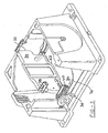
- Circular saw blade 22 is rotated by a motor 28 which powers saw blade 22 through a gear case 30.
- Bevel adjustment mechanism 24 adjusts the angular position of saw blade 22 by pivoting saw blade 22, motor 28 and gear case 30.
- Height adjustment mechanism 26 adjusts the cutting depth of saw blade 22 by longitudinal movement of saw blade 22, motor 28 and gear case 30.
- bevel adjustment mechanism 24 comprises a pair of pivot quadrants 32, a support plate 34, and a locking system 36.
- Each pivot quadrant 32 is attached to a plurality of bosses 38 extending from the bottom of work table 14 using a plurality of bolts 40.
- Each pivot quadrant 32 is designed to pivot around a centre which is located on working surface 16 of work table 14 coincident with the plane of saw blade 22.
- the axis for pivoting support plate 34 lies on working surface 16 and extends through the plane of saw blade 22 when saw blade 22 is generally perpendicular with working surface 16.
- pivot quadrant 32 is comprised of a support bracket 42, a pivot bracket 44 and a retaining strap 46.
- Support bracket 42 is an L-shaped bracket which defines a plurality of holes 48 to facilitate the attachment of pivot quadrant 32 to work table 14 on one leg of the L.
- the opposite leg of the L defines an arcuate slot 50 which controls the pivotal movement of pivot bracket 44 and locates the centre of the pivoting at working surface 16 of work table 14.
- Pivot bracket 44 extends between support bracket 42 and support plate 34 and defines a plurality of holes 52 at one end to facilitate the attachment of support plate 34.
- the opposite end of pivot bracket 44 defines a stamped arcuate protrusion 54 which mates with slot 50 to control the pivoting of pivot bracket 44.
- Protrusion 54 is formed out of the material of pivot bracket 44 and this forming operation defines an arcuate slot 56 once protrusion 54 has been formed.
- Retaining strap 46 extends across pivot bracket 44 and is attached to support bracket 42 to maintain the engagement of protrusion 54 with slot 50.
- Retaining strap 46 defines a formed protrusion 58 which extends into slot 56 to both guide the pivotal movement of pivot bracket 44 and to act as a stop to limit the pivotal movement of pivot bracket 44.
- support plate 34 is a shallow drawn plate which is attached to pivot quadrants 32.
- Support plate 34 is designed to support both height adjustment mechanism 26 and locking system 36.
- Locking system 36 comprises a bearing block 60, a locking rod 62, a locking arm 64, a bearing block cam 66, a locking arm cam 68 and a return spring 70.
- Bearing block 60 is a curved member which is attached to a bracket 72 which is in turn attached to support plate 34. Bearing block 60 thus pivots with support plate 34 and bearing block 60 extends through an arcuate slot 74 in the front face of base 12. While the pivotal movement of support plate 34 moves bearing block 60 within slot 74, it should be understood that the movement of support plate 34 is controlled by pivot quadrants 32 and that a clearance will always exist between bearing block 60 and slot 74.
- Locking rod 62 extends across support plate 34 and through bracket 72 and bearing block 60 in the front of support plate 34 and through a bracket 76 and a bracket 78 located at the rear of support plate 34.
- Bracket 76 is attached to support plate 34 and defines an aperture for accepting and guiding locking rod 62.
- Bracket 78 is attached to work table 14 and it defines an arcuate slot 80 which accepts locking rod 62 and allows for the pivotal movement of support plate 34. While the pivotal movement of support plate 34 moves locking rod 62 within slot 80, it should be understood that the movement of support plate 34 is controlled by pivot quadrants 32 and that a clearance will always exist between locking rod 62 and slot 80.
- locking rod 62 has been inserted through brackets 76 and 78, a washer 82 and a nut 84 are assembled to locking rod 62 to provide adjustment for locking system 34.
- the front end of locking rod 62 extends through bearing block 60 and through a D-shaped embossment 86 which is an integral part of bearing block 60.
- Locking arm 64 is assembled over the end of locking rod 62 and secured to locking rod 62 using a hardened washer 88, a thrust bearing 90, a hardened washer 92 and a nut 94 threadingly received on locking rod 62 as shown in Figure 4.
- Bearing block cam 66 and locking arm cam 68 are disposed between locking arm 64 and bearing block 60.
- D-shaped embossment 86 extends from bearing block 60 through slot 74 in the front face of base 12.
- Bearing block cam 66 includes a D-shaped aperture which mates with embossment 86 and cam 66 is positioned such that the front face of base 12 is sandwiched between bearing block 60 and bearing block cam 66.
- the engagement of the D-shaped aperture of cam 66 with D-shaped embossment 86 prohibits the rotational movement of cam 66 with respect to bearing block 60.
- the face of cam 66 opposite to the front surface of base 12 defines a camming surface 96 which reacts with locking arm cam 68 to activate locking system 34.
- Locking arm 64 defines a D-shaped embossment 98 which mates with a D-shaped aperture extending through locking arm cam 68 such that locking arm cam 68 pivots with locking arm 64 when locking arm 64 pivots on locking rod 62.
- the face of cam 68 opposite to locking arm 64 defines a camming surface 100 which mates with camming surface 96 on cam 66 such that pivoting motion of locking arm 64 with respect to locking rod 62 will cause longitudinal movement of locking rod 62 to activate locking system 36.
- Return spring 70 is disposed on locking rod 62 between an ear 102 formed on locking rod 62 and bearing block 60 in order to urge locking rod 62 towards the rear of base 12 or towards bracket 78.
- Locking rod 62 is shown with an additional ear 102 on the opposite side of return spring 70 to capture spring 70 in the unassembled condition of locking rod 62.
- the additional ear 102 requires that the aperture in bearing block 60 which accepts locking rod 62 be provided with a slot (not shown) to accept the additional ear 102. In this arrangement, the engagement of the additional ear 102 with the slot in bearing block 60 will prohibit any rotational movement of locking rod 62.
- locking system 36 is activated by pivoting locking arm 64 on locking rod 62 which rotates cam 68 with respect to cam 66.
- Camming surface 100 is cammed away from camming surface 96 causing longitudinal movement of locking rod 62.
- the longitudinal movement of locking rod 62 compresses support plate 34 between bracket 78 and the front face of base 12 due to washer 82 and nut 84 engaging bracket 78 and bearing block cam 66 engaging the front surface of base 12.
- the flexibility of locking rod 62 due to a centre off-set area 104 and the flexibility of bracket 78 permit the compression of support plate 34.
- the adjustment for locking system 36 is provided for by nut 84.
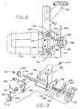
- height adjustment mechanism 26 comprises a pivot link 110, a biasing spring 112, a follower nut 114, a height adjustment screw 116 and a crank handle 118 which function to move saw blade 22, motor 28 and gear case 30 longitudinally with respect to support plate 34.
- Support plate 34 defines a generally rectangular opening 120 within which gear case 30 is located. Located adjacent to and extending generally the entire length of opening 120 are a pair of formed ribs 122 which provide stiffness to support plate 34.
- Gear case 30 includes a housing 124 disposed on one side of support plate 34 and a cover 126 disposed on the opposite side of support plate 34. Cover 126 is secured to housing 124 by a plurality of bolts 128 such that support plate 34 is sandwiched between cover 126 and housing 124.
- Gear case 30 includes a pair of longitudinally extending surfaces 130 which engage the opposing sides of opening 120 to guide the movement of gear case 30 within opening 120.
- Motor 28 is attached to housing 124 and includes an armature shaft 132 having a pinion 134 which meshes with an output gear 136 which is rotatably supported within gear case 30.
- the output gear includes an arbor shaft 138 which provides for the attachment of saw blade 22.
- cover 126 is provided with a plurality of accurately machined pads 140 which accurately position cover 126 and thus saw blade 22 with respect to support plate 34.
- Machined pads 140 are biased against the datum face on support plate 34 by a plurality of elastomeric springs 142 each of which is disposed within an aperture 144 defined by housing 124.
- a low friction wear pad 146 is disposed between each elastomeric spring 142 and support plate 34 to facilitate the movement of gear case 30 within opening 120.
- cover 126 includes an extension 148 which can be utilised for supporting a splitter and/or guard mechanism for table saw 10 if desired The mounting of the splitter and/or guard mechanism on cover 126 allows the components to travel with saw blade 22 during cutting depth and/or angular adjustments.
- pivot link 110 is pivotably secured to support plate 34 by an appropriate fastener 150.
- One arm of pivot link 110 defines a slot 152 which engages a pin 154 attached to gear case 30.
- the second arm of pivot link 110 defines a slot 156 which engages follower nut 114.
- Biasing spring 112 is a tension spring positioned around fastener 150 and is disposed between pivot link 110 and a retainer 158. Retainer 158 is attached to follower nut 114 and biasing spring 112 is positioned such that its spring force biases gear case 30 towards a downward position.
- Height adjustment screw 116 is rotatably secured at one end by a bracket 160 which is a separate component or bracket 160 can be formed out of support plate 34.
- a nylon bushing 162 is disposed between screw 116 and bracket 160 to facilitate the rotation of screw 116 and provide a smoothness of operation. The loading and thus the wear between screw 116, bushing 162 and bracket 160 is significantly reduced due to the reaction of spring 112 occurring through follower nut 114 and not through screw 116.
- the opposite end of adjustment screw 116 extends through and is rotatably supported by bearing block 60. The portion of adjustment screw 116 which extends beyond bearing block 60 is adapted for securing crank handle 118 to adjustment screw 116 such that rotation of crank handle 118 causes rotation of adjustment screw 116.
- a hardened washer 164 Disposed between bearing block 60 and bracket 72 of support plate 34 is a hardened washer 164, a powdered metal washer 166, a spring thrust washer 168 and a hardened washer 170.
- Powdered metal washer 166 is secured to adjustment screw 116 by press fitting or other means known in the art.
- the biasing of spring thrust washer 168 produces frictional resistance to the rotation of adjustment screw 116 allowing for the accurate positioning of saw blade 22 and the ability of height adjustment mechanism 26 to maintain the position of saw blade 22 during the cutting operation.
- the frictional resistance or drag produced by spring thrust washer 168 maintains the position of adjustment screw 116 and is not affected by the vibration produced by motor 28 and/or the cutting operation.
- the biasing produced by spring thrust washer 168 removes any play which may exist between the various components of height adjustment 26.
- Follower nut 114 is threadingly received on a threaded portion 172 of screw 116 which is located between bracket 160 and bearing block 60.
- follower nut 114 includes a cylindrical finger 174 which extends into retainer 158, into slot 156 of pivot link 110 and into a slot 176 located in support plate 34 to cause the pivoting of pivot link 110 by follower nut 114.
- Slot 176 in support plate 34 prohibits rotation of follower nut 114 and tends to guide follower nut 114 as it moves along screw 116.
- the contact between finger 174 and the edge of slot 176 provides the reaction point for spring 112.
- crank handle 118 when crank handle 118 is rotated, adjustment screw 116 is rotated which causes follower nut 114 to move longitudinally along threaded portion 172 of adjustment screw 116.
- the direction of movement of follower nut 114 will be determined by the design of threaded portion 172 and the direction of rotation of crank handle 118.
- the longitudinal movement of follower nut 114 causes pivotal movement of pivot link 110 due to the engagement of finger 174 which engages slot 156.
- the pivotal movement of pivot link 110 causes the longitudinal movement of gear case 30, motor 28 and saw blade 22 due to the engagement of slot 152 with pin 154.
- the longitudinal movement of gear case 30, motor 28 and saw blade 22 sets the height of saw blade 22 extending through work table 14 and thus the depth of cut.
- cover 126 of gear case 30 supports another unique feature for machine tool 10.
- One of the problems associated with machine tools is the changing of the cutting tool.
- Saw blade 22 is assembled to arbor shaft 138 and is frictionally held in position by a pair of washers 180, 182 and an arbor nut 184.
- Arbor shaft 138 includes a pair of flats 186 which accept a wrench (not shown) in order to stop arbor shaft 138 from rotating when arbor nut 184 is to be loosened or tightened during the changing of saw blade 22.
- the wrench for engaging flats 186 is normally a separate piece which is easily misplaced which then leads to the wedging of a block of wood or other material against saw blade 22 to hold arbor shaft 138.
- the wedging of the block against saw blade 22 is both dangerous and leads to unnecessary loading of the bearings supporting arbor shaft 138.
- the present invention includes a lever 188 which is pivotably secured to cover 126.
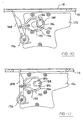
- a wrench 190 is pivotably secured to lever 188 and moves within a pocket 192 formed by a ridge 194 which is an integral part of cover 126 between an unlocked position shown in Figure 10 and a locked position shown in Figure 11.
- a spring 196 biases wrench 190 into its unlocked position.
- the unlocked position of wrench 190 is shown in Figure 10 where wrench 190 is disconnected from flats 186 and arbor shaft 138 is free to rotate.
- the locked position is shown in Figure 11 where wrench 190 engages flats 186 to prohibit rotation of arbor shaft 138.
- the end of wrench 190 engages ridge 194 at both the front of wrench 190 adjacent arbor shaft 138 to provide support for wrench 190 in the locked position and at the rear of wrench 190 adjacent to lever 188 to provide support to counteract the torque being allied to arbor nut 184.
- Lever 188 is accessible to the operator of table saw 10 through the opening in work table 14 which accepts throat plate 18.
- Lever 188 is designed to extend into the throat plate opening of work table 14 when wrench 190 is in the locked position and saw blade 22 is in its full upward position as shown in Figure 11 to prohibit the assembly of throat plate 18 with work table 14 while wrench 190 is in the locked position. Once wrench 190 is moved to its unlocked position, lever 188 will be removed from the throat plate opening in work table 14 and throat plate 18 can be assembled to work table 14.
- Figure 12 illustrates a bevel angle stop system for bevel adjustment mechanism 24.
- An adjustment cam 200 is attached to the front panel of work table 14 at opposite ends of slot 74.
- a protrusion 202 is formed at both ends of bearing block 60.
- Adjustment cam 200 is tightened in position using a bolt 204 to set the zero degree position of saw blade 22. The tightening of bolt 204 has a tendency to rotate cam 200 in a clockwise direction.
- cam 200 urges cam 200 into contact with protrusion 202 due to the external spiral shape of cam 200 to provide an accurate positioning of the bevel angle for saw blade 22.
- the perpendicularity of saw blade 22 can be set by a square or other means known well in the art.
- the 45° position of saw blade 22 with respect to working surface 16 can be set by a similar adjustment and locking of adjustment cam 200 located on the opposite side of slot 74.
Claims (8)
- Werkzeugmaschine (10) mit
einem eine Arbeitsfläche (16) bildenden Arbeitstisch (14), einem am Arbeitstisch (14) angebrachten und bezüglich diesem bewegbaren Schneidwerkzeug (22) und einem Mechanismus zum Anordnen des Schneidwerkzeugs (22) relativ zu der Arbeitsfläche (16) des Arbeitstischs (14), wobei der Mechanismus aufweist:eine schwenkbar am Arbeitstisch (14) befestigte Halteplatte (34), wobei das Schneidwerkzeug (22) an der Halteplatte (34) angebracht ist, um sich zwischen einer ersten Stellung, in der sich das Schneidwerkzeug durch eine Öffnung (20) in dem Arbeitstisch (14) erstreckt, und einer zweiten Stellung, in der das Schneidwerkzeug (22) unter der Arbeitsfläche (16) angeordnet ist, zu bewegen,einen Anhebemechanismus (26) für das Schneidwerkzeug, der an der Halteplatte (34) befestigt ist und zum Bewegen des Schneidwerkzeugs (22) zwischen der der ersten Stellung und der zweiten Stellung betätigbar ist,einen an der Halteplatte (34) befestigten Winkeleinstellmechanismus (24) für das Schneidwerkzeug, der zum Verschwenken der Halteplatte (34) bezüglich dem Arbeitstisch betätigbar ist, so dass das Schneidwerkzeug (22) bezüglich der Arbeitsfläche (16) winkelverstellt werden kann, wobei der Winkeleinstellmechanismus umfasst: mindestens einen Schwenkquadranten (32) zum schwenkbaren Befestigen der Halteplatte (34) am Arbeitstisch (14), wobei der mindestens eine Schwenkquadrant einen am Arbeitstisch (14) angebrachten Haltebügel (42) aufweist,einen schwenkbar am Haltebügel (42) angebrachten und fest an der Halteplatte (34) angebrachten Schwenkbügel (44);wobei die Werkzeugmaschine (10) gekennzeichnet ist durch einen am Haltebügel (42) angebrachten Haltestreifen (46), der in Eingriff mit dem Schwenkbügel (44) steht, um dessen Anbringung am Haltebügel (42) aufrechtzuerhalten. - Werkzeugmaschine nach Anspruch 1, dadurch gekennzeichnet, dass die Halteplatte (34) um eine Achse schwenkt, die in der Arbeitsfläche (16) liegt.
- Werkzeugmaschine nach einem der vorhergehenden Ansprüche, dadurch gekennzeichnet, dass der Arbeitstisch (14) mindestens einen einstellbaren Anschlag hat, der einen drehbar am Arbeitstisch (14) befestigten Nocken (200) hat, der wahlweise in mehrere Stellungen einstellbar am Arbeitstisch (14) verriegelt werden kann, um die Verschwenkung der Halteplatte (34) zu begrenzen.
- Werkzeugmaschine nach einem der vorhergehenden Ansprüche, dadurch gekennzeichnet, dass der Anhebemechanismus (26) ferner aufweist:eine drehbar an der Halteplatte (34) befestigte Einstellschraube (116),eine in Schraubeingriff mit der Einstellschraube (116) stehende Einstellmutter (114), so dass eine Drehung der Einstellschraube (116) die Einstellmutter (114) in Längsrichtung entlang der Einstellschraube (116) bewegt, undeine schwenkbar an der Halteplatte (34) befestigte Schwenkkulisse (110), die sich zwischen der Einstellmutter (114) und dem Schneidwerkzeug (22) erstreckt, so dass eine Drehung der Einstellschraube (116) ein Schwenken der Schwenkkulisse (110) bewirkt, um das Schneidwerkzeug (22) zwischen den ersten und zweiten Stellungen zu bewegen.
- Werkzeugmaschine nach Anspruch 4, dadurch gekennzeichnet, dass sie ferner ein Vorspannelement (112) zum Drücken des Schneidwerkzeugs (22) in eine der ersten und zweiten Stellungen aufweist.
- Werkzeugmaschine nach Anspruch 4 oder 5, dadurch gekennzeichnet, dass sie ferner Mittel zum Widerstand gegen eine Drehung der Einstellschraube (116) aufweist.
- Werkzeugmaschine nach Anspruch 6, dadurch gekennzeichnet, dass die Mittel zum Widerstehen eine an der Einstellschraube (116) angebrachte Scheibe (166) und ein Vorspannelement (168) zum Drücken der Scheibe (166) gegen die Halteplatte (34) aufweist, um Reibungswiderstand gegen die Drehung der Einstellschraube (116) zu erzeugen.
- Werkzeugmaschine nach einem der vorhergehenden Ansprüche, dadurch gekennzeichnet, dass das Schneidwerkzeug (22) gegen eine Fläche der Halteplatte (34) vorgespannt ist.
Applications Claiming Priority (3)
| Application Number | Priority Date | Filing Date | Title |
|---|---|---|---|
| US08/663,538 US5875698A (en) | 1996-06-17 | 1996-06-17 | Blade and motor carrier with height/angle adjustment mechanism |
| US663538 | 1996-06-17 | ||
| EP97304144A EP0813938B1 (de) | 1996-06-17 | 1997-06-13 | Schneidblatt- und Motorträger mit Höhe/Winkel-Einstellvorrichtung |
Related Parent Applications (1)
| Application Number | Title | Priority Date | Filing Date |
|---|---|---|---|
| EP97304144A Division EP0813938B1 (de) | 1996-06-17 | 1997-06-13 | Schneidblatt- und Motorträger mit Höhe/Winkel-Einstellvorrichtung |
Publications (3)
| Publication Number | Publication Date |
|---|---|
| EP1577066A2 EP1577066A2 (de) | 2005-09-21 |
| EP1577066A3 EP1577066A3 (de) | 2005-11-09 |
| EP1577066B1 true EP1577066B1 (de) | 2007-08-22 |
Family
ID=24662266
Family Applications (5)
| Application Number | Title | Priority Date | Filing Date |
|---|---|---|---|
| EP05010598A Expired - Lifetime EP1577067B1 (de) | 1996-06-17 | 1997-06-13 | Schneidblatt- und Motorträger mit Höhe/Winkel-Einstellvorrichtung |
| EP05010596A Expired - Lifetime EP1577065B1 (de) | 1996-06-17 | 1997-06-13 | Schneidblatt- und Motorträger mit Höhe/Winkel-Einstellvorrichtung |
| EP97304144A Expired - Lifetime EP0813938B1 (de) | 1996-06-17 | 1997-06-13 | Schneidblatt- und Motorträger mit Höhe/Winkel-Einstellvorrichtung |
| EP05010599A Expired - Lifetime EP1616677B1 (de) | 1996-06-17 | 1997-06-13 | Schneidblatt- und Motorträger mit Höhe/Winkel-Einstellvorrichtung |
| EP05010597A Expired - Lifetime EP1577066B1 (de) | 1996-06-17 | 1997-06-13 | Schneidblatt- und Motorträger mit Höhe/Winkel-Einstellvorrichtung |
Family Applications Before (4)
| Application Number | Title | Priority Date | Filing Date |
|---|---|---|---|
| EP05010598A Expired - Lifetime EP1577067B1 (de) | 1996-06-17 | 1997-06-13 | Schneidblatt- und Motorträger mit Höhe/Winkel-Einstellvorrichtung |
| EP05010596A Expired - Lifetime EP1577065B1 (de) | 1996-06-17 | 1997-06-13 | Schneidblatt- und Motorträger mit Höhe/Winkel-Einstellvorrichtung |
| EP97304144A Expired - Lifetime EP0813938B1 (de) | 1996-06-17 | 1997-06-13 | Schneidblatt- und Motorträger mit Höhe/Winkel-Einstellvorrichtung |
| EP05010599A Expired - Lifetime EP1616677B1 (de) | 1996-06-17 | 1997-06-13 | Schneidblatt- und Motorträger mit Höhe/Winkel-Einstellvorrichtung |
Country Status (5)
| Country | Link |
|---|---|
| US (5) | US5875698A (de) |
| EP (5) | EP1577067B1 (de) |
| CN (1) | CN1064574C (de) |
| CA (1) | CA2207765A1 (de) |
| DE (5) | DE69737575T2 (de) |
Families Citing this family (143)
| Publication number | Priority date | Publication date | Assignee | Title |
|---|---|---|---|---|
| USD425918S (en) * | 1999-05-21 | 2000-05-30 | Black & Decker Inc. | Throat plate for a table saw |
| US5875698A (en) * | 1996-06-17 | 1999-03-02 | Black & Decker Inc. | Blade and motor carrier with height/angle adjustment mechanism |
| US5857507A (en) * | 1996-09-20 | 1999-01-12 | Black & Decker Inc. | Table saw |
| EP0875324B1 (de) * | 1997-04-29 | 2006-09-27 | Black & Decker Inc. | Tischsäge |
| US6109157A (en) * | 1999-06-09 | 2000-08-29 | S-B Power Tool Company | Arbor locking mechanism |
| US6530303B1 (en) * | 1999-06-10 | 2003-03-11 | Black & Decker Inc. | Table saw |
| EP1834742A1 (de) | 1999-06-10 | 2007-09-19 | Black & Decker, Inc. | Untertischkreissäge |
| US6493698B1 (en) * | 1999-07-26 | 2002-12-10 | Intel Corporation | String search scheme in a distributed architecture |
| US8061245B2 (en) * | 2000-09-29 | 2011-11-22 | Sd3, Llc | Safety methods for use in power equipment |
| US7210383B2 (en) * | 2000-08-14 | 2007-05-01 | Sd3, Llc | Detection system for power equipment |
| US7231856B2 (en) * | 2001-06-13 | 2007-06-19 | Sd3, Llc | Apparatus and method for detecting dangerous conditions in power equipment |
| US9927796B2 (en) | 2001-05-17 | 2018-03-27 | Sawstop Holding Llc | Band saw with improved safety system |
| US20020017179A1 (en) * | 2000-08-14 | 2002-02-14 | Gass Stephen F. | Miter saw with improved safety system |
| US7225712B2 (en) | 2000-08-14 | 2007-06-05 | Sd3, Llc | Motion detecting system for use in a safety system for power equipment |
| US20030056853A1 (en) | 2001-09-21 | 2003-03-27 | Gass Stephen F. | Router with improved safety system |
| US7836804B2 (en) | 2003-08-20 | 2010-11-23 | Sd3, Llc | Woodworking machines with overmolded arbors |
| US8459157B2 (en) | 2003-12-31 | 2013-06-11 | Sd3, Llc | Brake cartridges and mounting systems for brake cartridges |
| US7171879B2 (en) * | 2001-07-02 | 2007-02-06 | Sd3, Llc | Discrete proximity detection system |
| US7712403B2 (en) * | 2001-07-03 | 2010-05-11 | Sd3, Llc | Actuators for use in fast-acting safety systems |
| US6857345B2 (en) | 2000-08-14 | 2005-02-22 | Sd3, Llc | Brake positioning system |
| US7284467B2 (en) * | 2000-08-14 | 2007-10-23 | Sd3, Llc | Apparatus and method for detecting dangerous conditions in power equipment |
| US20050139056A1 (en) * | 2003-12-31 | 2005-06-30 | Gass Stephen F. | Fences for table saws |
| US7377199B2 (en) | 2000-09-29 | 2008-05-27 | Sd3, Llc | Contact detection system for power equipment |
| US7600455B2 (en) | 2000-08-14 | 2009-10-13 | Sd3, Llc | Logic control for fast-acting safety system |
| US9724840B2 (en) | 1999-10-01 | 2017-08-08 | Sd3, Llc | Safety systems for power equipment |
| US8065943B2 (en) | 2000-09-18 | 2011-11-29 | Sd3, Llc | Translation stop for use in power equipment |
| US7827890B2 (en) | 2004-01-29 | 2010-11-09 | Sd3, Llc | Table saws with safety systems and systems to mount and index attachments |
| US7610836B2 (en) * | 2000-08-14 | 2009-11-03 | Sd3, Llc | Replaceable brake mechanism for power equipment |
| US7707920B2 (en) | 2003-12-31 | 2010-05-04 | Sd3, Llc | Table saws with safety systems |
| US7024975B2 (en) | 2000-08-14 | 2006-04-11 | Sd3, Llc | Brake mechanism for power equipment |
| US7536238B2 (en) | 2003-12-31 | 2009-05-19 | Sd3, Llc | Detection systems for power equipment |
| US6957601B2 (en) * | 2000-08-14 | 2005-10-25 | Sd3, Llc | Translation stop for use in power equipment |
| US6889585B1 (en) * | 2000-01-04 | 2005-05-10 | International Business Machines Corporation | Cutter blade position detection mechanism and method of reporting cutter malfunction |
| US6283002B1 (en) * | 2000-01-28 | 2001-09-04 | Pei-Lieh Chiang | Table saw apparatus |
| SE515999C2 (sv) * | 2000-03-10 | 2001-11-05 | Electrolux Ab | Låspinne i ett bärbart motorredskap |
| FI109227B (fi) * | 2000-03-15 | 2002-06-14 | Goeran Sundholm | Palo-ovi ja palonsuojausjärjestelmä |
| US6813983B2 (en) | 2000-09-29 | 2004-11-09 | Sd3, Llc | Power saw with improved safety system |
| US6826988B2 (en) * | 2000-09-29 | 2004-12-07 | Sd3, Llc | Miter saw with improved safety system |
| US6502493B1 (en) * | 2001-06-27 | 2003-01-07 | Emerson Electric Co. | Table saw blade heel adjuster |
| ES2291444T3 (es) * | 2002-02-11 | 2008-03-01 | Anchor Lamina, Inc. | Simulador de accion de presion para el ajuste de una leva aerea. |
| US6684750B2 (en) * | 2002-04-29 | 2004-02-03 | Shi-Hui Yu | Structure of a connection seat and a suspension seat of the connection seat for a suspension round saw |
| US20030233921A1 (en) * | 2002-06-19 | 2003-12-25 | Garcia Jaime E. | Cutter with optical alignment system |
| US6736044B2 (en) * | 2002-10-07 | 2004-05-18 | Chin-Chin Chang | Table saw having a blade suspension structure |
| US6748838B1 (en) * | 2002-12-06 | 2004-06-15 | Chang Chin-Chin | Table saw having a rotation structure |
| DE10302066A1 (de) * | 2003-01-21 | 2004-07-29 | Kolbus Gmbh & Co. Kg | Vorrichtung zum Trennsägen von Doppelnutzen |
| DE102004023273A1 (de) * | 2003-05-12 | 2005-01-20 | Protomach Inc., St-Louis-De-Blandforf | Automatisierte Doppelsäge |
| US7201192B2 (en) * | 2003-06-25 | 2007-04-10 | Dino Makropoulos | Extendable woodworking system |
| US20060101958A1 (en) * | 2003-07-31 | 2006-05-18 | Garcia Jaime E | Table saw |
| US7131364B2 (en) * | 2003-08-25 | 2006-11-07 | Eastway Fair Company, Ltd. | Collapsible stand for a bench-top power tool |
| ITBO20030692A1 (it) * | 2003-11-19 | 2005-05-20 | Gd Spa | Unita' di taglio per bachi continui di sigaretta. |
| US7980325B2 (en) * | 2004-01-16 | 2011-07-19 | Credo Technology Corporation | Rotating shaft locking mechanism |
| US7231858B2 (en) * | 2004-04-13 | 2007-06-19 | Robert Bosch Gmbh | Table saw having a measurement and display system |
| US7245981B2 (en) * | 2004-05-26 | 2007-07-17 | Precision Automation, Inc. | Material handling system with saw and wheel drag mechanism |
| ES2290825T3 (es) * | 2004-07-07 | 2008-02-16 | Black & Decker Inc. | Mecanismo de control de profundidad para sierra de mesa. |
| TWM279474U (en) * | 2004-07-21 | 2005-11-01 | Rexon Ind Corp Ltd | Ribbon saw |
| US20060016305A1 (en) * | 2004-07-22 | 2006-01-26 | Urmson James F | Apparatus for trimming a work piece |
| US7287453B2 (en) * | 2005-03-10 | 2007-10-30 | Sheng-Hsien Kuo | Woodworking table with an auxiliary device |
| US20060201300A1 (en) * | 2005-03-11 | 2006-09-14 | Schwaiger Barry M | Cutting tool and parts and accessories therefor |
| US8006596B2 (en) * | 2005-03-11 | 2011-08-30 | Walter Meier (Manufacturing) Inc. | Cutting tool and parts and accessories therefor |
| US20060201302A1 (en) * | 2005-03-11 | 2006-09-14 | Schwaiger Barry M | Cutting tool and parts and accessories therefor |
| TWM272659U (en) * | 2005-04-01 | 2005-08-11 | Durq Machinery Corp | Calibrating structure for saw blade of platform saw |
| GB2425281B (en) * | 2005-04-22 | 2007-12-05 | Rexon Ind Corp Ltd | Tilt angle display device for a circular saw machine |
| TWM275939U (en) * | 2005-04-26 | 2005-09-21 | Durq Machinery Corp | Sawing and cutting worktable |
| DE202005009377U1 (de) * | 2005-06-14 | 2006-10-26 | Metabowerke Gmbh | Werkzeugmaschine |
| TW200732116A (en) * | 2005-08-26 | 2007-09-01 | Positec Power Tools Suzhou Co | The table saw |
| CN100589910C (zh) * | 2005-08-26 | 2010-02-17 | 苏州宝时得电动工具有限公司 | 台锯 |
| FR2890053B1 (fr) * | 2005-08-31 | 2010-03-19 | Valeo Systemes Thermiques | Capuchon pour un conteneur contenant un agent volatil de traitement d'air |
| US20070074613A1 (en) * | 2005-10-04 | 2007-04-05 | Ben Yu | Worktable having adjustable shield |
| TWM291355U (en) * | 2005-10-12 | 2006-06-01 | Rexon Ind Corp Ltd | Circular saw |
| US20070095177A1 (en) * | 2005-10-27 | 2007-05-03 | Iannelli Joseph Sr | Mounting apparatus for an electric saw |
| TWM289693U (en) * | 2005-11-14 | 2006-04-21 | Durq Machinery Corp | Angle adjusting device for a tablesaw machine |
| DE202006001808U1 (de) * | 2006-02-02 | 2007-06-06 | Otto Martin Maschinenbau Gmbh & Co. Kg | Holzbearbeitungsmaschine, insbesondere Kreissäge mit einem Bearbeitungswerkzeug |
| US7602137B2 (en) * | 2006-02-20 | 2009-10-13 | Black & Decker Inc. | Electronically commutated motor and control system |
| DE102006010433B4 (de) * | 2006-03-03 | 2008-11-13 | Scheppach Fabrikation Von Holzbearbeitungsmaschinen Gmbh | Holzbearbeitungsmaschine mit einem Schwenkrahmen |
| US8584564B2 (en) | 2006-04-21 | 2013-11-19 | Black & Decker Inc. | Table saw |
| US20080006133A1 (en) * | 2006-07-05 | 2008-01-10 | Bor-Yann Chuang | Saw blade disassembling device for a table saw |
| US20080006135A1 (en) * | 2006-07-10 | 2008-01-10 | Thomas Desmet | I-joist cutting jig |
| US7792602B2 (en) * | 2006-08-22 | 2010-09-07 | Precision Automation, Inc. | Material processing system and a material processing method including a saw station and an interface with touch screen |
| US7476146B2 (en) * | 2007-05-11 | 2009-01-13 | Mark Bagby | Universal fixture for belt sander |
| US20090038459A1 (en) * | 2007-07-23 | 2009-02-12 | Wade Burch | Lighting System for a Table Saw |
| US20090272243A1 (en) * | 2008-05-02 | 2009-11-05 | Jean-Francois Desrosiers | Automated double saw |
| WO2010009861A1 (de) * | 2008-07-22 | 2010-01-28 | Gerhard Weusthof | Kapp- und gehrungssäge |
| TW201021945A (en) * | 2008-12-02 | 2010-06-16 | Durq Machinery Corp | Saw blade adjusting structure of table saw |
| CN101508121B (zh) * | 2009-03-03 | 2012-07-04 | 浙江世友木业有限公司 | 一种木地板表面纹理处理的方法 |
| US20110041667A1 (en) * | 2009-08-20 | 2011-02-24 | Pei-Fang Chiang | Mechanism for adjusting blade height of bench saw |
| US8297159B2 (en) * | 2009-08-26 | 2012-10-30 | Robert Bosch Gmbh | Table saw with dropping blade |
| US20110100183A1 (en) * | 2009-11-03 | 2011-05-05 | John Tomaino | Table saw blade height and angle adjustment mechanism |
| CN101940520B (zh) * | 2010-09-03 | 2012-05-23 | 迈柯唯医疗设备(苏州)有限公司 | 一种智能手术平台台面水平移动控制装置 |
| IT1402287B1 (it) * | 2010-10-08 | 2013-08-28 | Rollmatic S R L | Macchina affettatrice per prodotti alimentari |
| CN103376236B (zh) * | 2012-04-17 | 2018-12-18 | 深圳迈瑞生物医疗电子股份有限公司 | 光学检测系统和生化分析仪及其调节方法、光束定向组件 |
| US9556667B2 (en) * | 2012-05-01 | 2017-01-31 | The Boeing Company | Method and apparatus for establishing an environmentally isolated volume |
| CN103786193A (zh) * | 2012-11-02 | 2014-05-14 | 仇世宇 | 台锯 |
| EP2969340B1 (de) * | 2013-03-13 | 2021-11-17 | Robert Bosch GmbH | Gehrungstischsäge |
| WO2014160066A1 (en) | 2013-03-13 | 2014-10-02 | Robert Bosch Gmbh | Height adjustment mechanism for power tool |
| US9731362B2 (en) * | 2013-08-14 | 2017-08-15 | Black & Decker Inc. | Table saw |
| US9073231B2 (en) * | 2013-09-05 | 2015-07-07 | Chin-Chin Chang | Supports for a table saw blade assembly |
| US9186734B2 (en) * | 2013-10-16 | 2015-11-17 | Chin-Chin Chang | Height adjustment mechanism of table saw |
| CN105081447A (zh) * | 2014-05-22 | 2015-11-25 | 南京德朔实业有限公司 | 台型动力切割机 |
| US20160082529A1 (en) * | 2014-09-22 | 2016-03-24 | Sd3, Llc | Blade elevation mechanisms and anti-backdrive mechanisms for table saws |
| CN104385379A (zh) * | 2014-11-14 | 2015-03-04 | 金岳(天津)金属制品有限公司 | 一种床板切割设备 |
| CN104385378A (zh) * | 2014-11-14 | 2015-03-04 | 金岳(天津)金属制品有限公司 | 一种实木床加工设备 |
| EP3224009B1 (de) * | 2014-11-24 | 2021-08-04 | Nanjing Chervon Industry Co., Ltd. | Verbesserungen an einer tragbaren tischsäge |
| US10071432B2 (en) * | 2015-03-12 | 2018-09-11 | Robert Bosch Tool Corporation | Power tool with arbor lock |
| US9687922B2 (en) * | 2015-03-12 | 2017-06-27 | Robert Bosch Tool Corporation | Power tool with cammed throat plate |
| DE202015002508U1 (de) | 2015-04-01 | 2015-05-05 | Weinig Dimter Gmbh & Co. Kg | Sägeaggregat zum Sägen von Werkstücken aus Holz, Kunststoff und dergleichen |
| CN105251643A (zh) * | 2015-11-24 | 2016-01-20 | 吴美俊 | 一种防磨损的热水器出水喷头组件 |
| CN105363613A (zh) * | 2015-11-24 | 2016-03-02 | 晋江市晋美日用品有限公司 | 一种防尘的热水器出水喷头组件 |
| CN105344536A (zh) * | 2015-11-24 | 2016-02-24 | 余储 | 一种防断电的散热型热水器出水喷头组件 |
| US10603819B2 (en) | 2015-12-16 | 2020-03-31 | Black & Decker Inc. | Tile saw |
| CN105855616A (zh) * | 2016-06-02 | 2016-08-17 | 常州市金海珑机械制造有限公司 | 一种可调节的切割装置 |
| CN106077815A (zh) * | 2016-06-28 | 2016-11-09 | 安庆天蛛外墙清洗有限公司 | 一种铝型材切割设备 |
| CN106363702A (zh) * | 2016-11-23 | 2017-02-01 | 佛山市豪伟德机械有限公司 | 一种数控裁板锯的锯片智能升降装置 |
| CN106346561B (zh) * | 2016-11-23 | 2019-07-05 | 佛山市豪伟德机械有限公司 | 一种数控裁板锯的不停机调节锯片结构 |
| CN106363703B (zh) * | 2016-11-23 | 2018-12-21 | 佛山市豪伟德机械有限公司 | 一种数控裁板锯的锯车结构 |
| US10933554B2 (en) * | 2017-05-25 | 2021-03-02 | Sawstop Holding Llc | Power saws |
| CN207189852U (zh) | 2017-06-05 | 2018-04-06 | 米沃奇电动工具公司 | 台锯 |
| CN107584576A (zh) * | 2017-06-14 | 2018-01-16 | 南宁市益诚安防设备有限公司 | 一种木材切割机 |
| CN109203086A (zh) * | 2017-07-01 | 2019-01-15 | 泰州森港机器人有限公司 | 一种智能化安全电锯 |
| CN107379146A (zh) * | 2017-08-30 | 2017-11-24 | 福建省顺昌县升升木业有限公司 | 一种用于木材加工的全自动拉槽机 |
| CN108247766A (zh) * | 2018-01-07 | 2018-07-06 | 金世杰 | 一种带有保护功能的切割装置 |
| US10807174B2 (en) | 2018-02-20 | 2020-10-20 | Robert Bosch Tool Corporation | Saw blade height adjustment mechanism |
| JP7049145B6 (ja) * | 2018-03-16 | 2022-04-19 | 株式会社マキタ | 電動工具 |
| CN108582519A (zh) * | 2018-07-12 | 2018-09-28 | 安徽天筑远大住宅产业化科技有限公司 | 一种轻质隔墙安装切割装置 |
| CN109049149B (zh) * | 2018-07-16 | 2021-04-16 | 南京搏峰电动工具有限公司 | 台锯斜切极限限位角度快速切换结构 |
| CN109262794A (zh) * | 2018-10-08 | 2019-01-25 | 浙江花景木业有限公司 | 便于定位的木地板切割装置 |
| CN109397165A (zh) * | 2018-12-25 | 2019-03-01 | 东莞堡威自动化科技有限公司 | 一种动力刀座专用扳手 |
| US11213971B2 (en) * | 2019-03-27 | 2022-01-04 | Sawstop Holding Llc | Adjustable blade guard with dust collection |
| JP7254623B2 (ja) * | 2019-05-22 | 2023-04-10 | 株式会社マキタ | 電動工具 |
| CN110405828B (zh) * | 2019-07-26 | 2020-12-04 | 浙江德钜铝业有限公司 | 一种自动板材切割设备 |
| US11224924B2 (en) * | 2020-01-20 | 2022-01-18 | Robert Benjamin Joiner | Table miter saw |
| CN112171755A (zh) * | 2020-09-23 | 2021-01-05 | 章鸽子 | 一种建筑装饰板加工机 |
| CN112170950A (zh) * | 2020-09-30 | 2021-01-05 | 广州森宇达科技有限公司 | 一种具有夹紧功能的新材料切割装置 |
| US20220111549A1 (en) * | 2020-10-08 | 2022-04-14 | Robert Bosch Gmbh | Adjustable Bevel Angle Stops With Quick Release and Over-Ride Features |
| CN112440356A (zh) * | 2020-11-02 | 2021-03-05 | 魏秀菊 | 一种竹片修边削角器 |
| CN112720662A (zh) * | 2020-12-14 | 2021-04-30 | 九江中科鑫星新材料有限公司 | 一种超高分子聚乙烯管料的加工设备 |
| CN112756677B (zh) * | 2020-12-20 | 2024-01-26 | 广东兴奇新材料有限公司 | 一种铝合金型材加工用切割装置 |
| CN112847849B (zh) * | 2021-01-30 | 2022-09-16 | 中营晨旭建设有限公司 | 一种建筑加气混凝土砌块切割装置 |
| CN113245619A (zh) * | 2021-04-15 | 2021-08-13 | 郝志鹏 | 一种可多重角度调节的加工装置 |
| CN114083053B (zh) * | 2022-01-17 | 2022-04-08 | 南通新华装饰工程有限公司 | 门窗型材高精密加工用数控任意角度切割锯床 |
| CN114559094A (zh) * | 2022-04-12 | 2022-05-31 | 中原城建集团有限公司 | 一种装配式建筑用切割装置 |
| CN114986585B (zh) * | 2022-04-20 | 2024-03-08 | 南通吉祥实业有限公司 | 一种复合板加工用裁切装置及其使用方法 |
| CN114918991B (zh) * | 2022-07-19 | 2022-11-04 | 山东劳动职业技术学院(山东劳动技师学院) | 一种计算机主板加工用的剪切装置 |
| CN117900556A (zh) * | 2024-03-15 | 2024-04-19 | 广东创高幕墙门窗工程有限公司 | 一种高精度切割装置 |
Family Cites Families (90)
| Publication number | Priority date | Publication date | Assignee | Title |
|---|---|---|---|---|
| US3169698A (en) * | 1965-02-16 | Locking and unlocking system for voting machine and the like | ||
| US366633A (en) * | 1887-07-12 | Machine | ||
| US1314291A (en) * | 1919-08-26 | Sawing | ||
| US636997A (en) * | 1899-07-01 | 1899-11-14 | Whitlock Machine Company | Rotary paper-cutter for printing-presses. |
| US741034A (en) * | 1902-12-24 | 1903-10-13 | Hazelton & Donald | Saw-table. |
| US963697A (en) * | 1909-01-21 | 1910-07-05 | Joseph Dyer | Sawing and mitering machine. |
| US1262185A (en) * | 1917-11-27 | 1918-04-09 | George C Jensen | Locking apparatus. |
| US1455426A (en) * | 1921-12-08 | 1923-05-15 | Clement D Charles | Circular-saw machine |
| US1523174A (en) * | 1923-09-10 | 1925-01-13 | Comeau Emile | Lock |
| US1593317A (en) * | 1924-10-10 | 1926-07-20 | Frank E Thomes | Woodworking machine |
| US1762023A (en) * | 1927-09-16 | 1930-06-03 | Chain Belt Co | Sawing machine |
| US1821113A (en) * | 1928-10-31 | 1931-09-01 | American Saw Mill Machinery Co | Mounting for rotary miter saws |
| US1922151A (en) * | 1931-07-27 | 1933-08-15 | William B Boice | Adjusting device for saw arbors |
| US1988102A (en) * | 1932-04-02 | 1935-01-15 | William H Woodward | Circular saw machine |
| US1993219A (en) * | 1933-07-12 | 1935-03-05 | Herberts Machinery Company Ltd | Circular saw |
| US2008673A (en) * | 1934-03-07 | 1935-07-23 | Walker Turner Company Inc | Power-driven tool |
| US2067652A (en) * | 1934-08-04 | 1937-01-12 | Herbert E Tautz | Woodworking machine |
| US2038810A (en) * | 1934-09-06 | 1936-04-28 | Delta Mfg Co | Circular-saw machine |
| US2106288A (en) * | 1934-09-27 | 1938-01-25 | Herbert E Tautz | Circular saw apparatus |
| US2097920A (en) * | 1935-05-27 | 1937-11-02 | Duro Metal Prod Co | Bench saw table |
| US2075282A (en) * | 1935-05-27 | 1937-03-30 | Duro Metal Prod Co | Bench saw |
| US2131492A (en) * | 1936-11-28 | 1938-09-27 | Walker Turner Company Inc | Tilting arbor table saw |
| US2168282A (en) * | 1936-12-18 | 1939-08-01 | Delta Mfg Co | Circular saw |
| US2121069A (en) * | 1937-06-14 | 1938-06-21 | Atlas Press Company | Circular saw |
| US2208582A (en) * | 1937-08-25 | 1940-07-23 | John R Hollister | Sawing machine |
| US2265407A (en) * | 1939-01-25 | 1941-12-09 | Delta Mfg Co | Tilting arbor saw |
| US2261696A (en) * | 1939-03-15 | 1941-11-04 | Walker Turner Co Inc | Tilting saw |
| US2299262A (en) * | 1940-04-29 | 1942-10-20 | Uremovich Mark | Power-driven bench saw |
| US2292872A (en) * | 1940-07-10 | 1942-08-11 | Elwyn A Eastman | Double hinge tilting arbor saw |
| US2312118A (en) * | 1940-07-31 | 1943-02-23 | Ray H Neisewander | Adjustable woodworking machine |
| US2601878A (en) * | 1946-03-08 | 1952-07-01 | St Paul Foundry & Mfg Co | Table saw with part of the table swingably and laterally adjustable |
| US2530290A (en) * | 1946-12-12 | 1950-11-14 | Atlas Press Company | Table saw with tiltable and vertically adjustable arbor |
| US2590035A (en) * | 1947-09-10 | 1952-03-18 | Pollak Abraham | Tilting-arbor saw and cradle suspension therefor |
| US2695638A (en) * | 1949-02-17 | 1954-11-30 | King Seeley Corp | Tilting arbor circular wood saw |
| US2518684A (en) * | 1949-04-21 | 1950-08-15 | Hyman M Harris | Duplex bench saw |
| US2626639A (en) * | 1950-11-04 | 1953-01-27 | Duro Metal Products Co | Belt and pulley drive means for tiltable saws and the like |
| US2625966A (en) * | 1951-06-01 | 1953-01-20 | Callender Foundry & Mfg Compan | Motor and belt drive for tilt arbor saws |
| US2711762A (en) * | 1951-12-08 | 1955-06-28 | King Seeley Corp | Arbor saw |
| US2661777A (en) * | 1952-09-15 | 1953-12-08 | Edgar J Hitchcock | Self-adjusting motor mounting for vertically adjusted saws |
| US2678071A (en) * | 1953-02-06 | 1954-05-11 | Duro Metal Products Co | Motor mounting and drive means for power tools |
| US2704560A (en) * | 1953-02-12 | 1955-03-22 | Gibraltar Mfg Co Inc | Tilt arbor bench saw |
| US2758615A (en) * | 1954-03-11 | 1956-08-14 | Hampden Brass And Aluminum Com | Mounting for tilting arbor rotary miter saws |
| US2810408A (en) * | 1954-06-11 | 1957-10-22 | Boice Crane Company | Adjustable mounting and drive mechanism for table saws |
| US2873773A (en) * | 1954-06-14 | 1959-02-17 | King Seeley Corp | Shiftable motor drive for tilting arbor saw |
| US3085602A (en) * | 1954-06-14 | 1963-04-16 | King Seeley Thermos Co | Tilting arbor saw |
| US2844173A (en) * | 1954-09-13 | 1958-07-22 | King Seely Corp | Arbor saw with single handle control of tilt and elevation |
| US2894546A (en) * | 1955-11-23 | 1959-07-14 | Yates American Machine Co | Combination saw, jointer, and sander tool |
| US2852047A (en) * | 1956-04-16 | 1958-09-16 | Duro Metal Products Co | Tilting and elevating mechanism for a disc type table saw |
| US2850054A (en) * | 1956-07-09 | 1958-09-02 | Yates American Machine Co | Tilting arbor saw |
| US2945516A (en) * | 1956-12-31 | 1960-07-19 | Yuba Cons Ind Inc | Tilting arbor table saw with coaxial control of elevation and tilt |
| US3021881A (en) * | 1956-12-31 | 1962-02-20 | Yuba Cons Ind Inc | Power saw |
| US3005477A (en) * | 1957-12-23 | 1961-10-24 | Horstmann & Sherwen Ltd | Rotary tool wood working machines |
| US3013592A (en) * | 1959-03-23 | 1961-12-19 | Theodore G Ambrosio | Tilting table saw |
| US3011529A (en) * | 1959-09-08 | 1961-12-05 | Rockwell Mfg Co | Tilt and elevating mechanism for tilting arbor saws |
| US3356111A (en) * | 1961-10-31 | 1967-12-05 | Rockwell Mfg Co | Power tool improvements |
| US3289713A (en) * | 1964-10-26 | 1966-12-06 | Emerson Electric Co | Machinery table insert |
| US3315715A (en) * | 1965-05-17 | 1967-04-25 | Moak Machine And Foundry Compa | Tilting arbor saw |
| US3344819A (en) * | 1965-10-20 | 1967-10-03 | Donald H Benson | Table saw |
| US3538964A (en) * | 1967-11-20 | 1970-11-10 | Rockwell Mfg Co | Motor driven table saw |
| US3581784A (en) * | 1969-11-21 | 1971-06-01 | Rockwell Mfg Co | Saw table insert |
| US3670788A (en) * | 1970-05-22 | 1972-06-20 | Henry M Pollak | Arbor saw |
| US4036093A (en) * | 1976-08-18 | 1977-07-19 | Excor, Inc. | Saw for cutting truss members, rafters and the like with dimensional accuracy |
| DE2646515A1 (de) * | 1976-10-15 | 1978-04-20 | Leopold Jaegers | Fuehrung fuer ein saegeblatt |
| DE2811615A1 (de) * | 1978-03-17 | 1979-09-27 | Lutz Eugen Masch | Gehrungssaege |
| US4276799A (en) * | 1979-04-18 | 1981-07-07 | Black & Decker Inc. | Power tool apparatus |
| US4249442A (en) * | 1979-07-25 | 1981-02-10 | Black & Decker Inc. | Elevation setting mechanism for a table saw and the like |
| US4297921A (en) * | 1979-08-10 | 1981-11-03 | Wally Wydra | Circular saw blade removing combination |
| US4270427A (en) * | 1980-02-04 | 1981-06-02 | Black & Decker Inc. | Bevel angle setting means for a power tool apparatus |
| WO1983001194A1 (en) * | 1981-10-01 | 1983-04-14 | Francisco Leoncio Cerqueira | Faeces collection and concentration receiver |
| US4516612A (en) * | 1982-09-03 | 1985-05-14 | Wiley Edward R | Multipurpose table saw |
| US4532844A (en) * | 1983-09-16 | 1985-08-06 | Chang Jen W | Device for supporting a circular saw of sawing machine |
| FR2559693B1 (fr) * | 1984-02-17 | 1987-04-17 | Smid Sa | Machine a scier les contours de plaques |
| US4599927A (en) * | 1985-05-08 | 1986-07-15 | Emerson Electric Co. | Tool elevation and bevel adjustment for direct drive power tool |
| DE3622904C1 (de) * | 1986-07-08 | 1987-10-01 | Neiman Gmbh | Lenkschloss zum Sperren der Drehbewegung einer Kraftfahrzeug-Lenkspindel |
| US4962685A (en) * | 1988-10-27 | 1990-10-16 | Hagstrom Oscar E | Production table saw |
| DE4016905C1 (en) * | 1988-11-26 | 1991-03-21 | Kuno 8316 Frontenhausen De Neuhierl | Circular saw for trimming wood - is used with table adjustable in height and fitted with clamp |
| DE3839997C1 (en) * | 1988-11-26 | 1990-05-10 | Kuno 8300 Landshut De Neuhierl | Panel-sizing saw |
| JPH0711921Y2 (ja) * | 1989-08-30 | 1995-03-22 | リョービ株式会社 | 作業台の刃物位置設定装置 |
| US5174349A (en) * | 1991-08-09 | 1992-12-29 | Skil Corporation | Power table saw assemblies having integral spare part storage |
| US5193428A (en) * | 1991-12-03 | 1993-03-16 | Michel Letendre | Assembly for conventional bench saw |
| US5437214A (en) * | 1992-05-22 | 1995-08-01 | Makita Corporation | Miter saw |
| GB9214269D0 (en) * | 1992-07-04 | 1992-08-19 | Black & Decker Inc | Tool mounting means and implement therefor |
| GB9218343D0 (en) * | 1992-08-28 | 1992-10-14 | Black & Decker Inc | A mounting apparatus |
| GB9425391D0 (en) * | 1994-12-12 | 1995-02-15 | Black & Decker Inc | Bevel table saw adjustment |
| CN2243358Y (zh) * | 1995-01-12 | 1996-12-25 | 陈德华 | 多功能高速切割机 |
| CN2219766Y (zh) * | 1995-03-11 | 1996-02-14 | 济南高新技术产业开发区快信实业有限公司 | 塑料门窗多用锯 |
| DE29506024U1 (de) * | 1995-04-07 | 1995-06-01 | Mey Kg Maschf Mafell | Tischkreissäge mit Sägeblatt-Stoppvorrichtung |
| US5870938A (en) * | 1995-12-12 | 1999-02-16 | Black & Decker Inc. | Bevel locking system for a sliding compound miter saw |
| US5875698A (en) * | 1996-06-17 | 1999-03-02 | Black & Decker Inc. | Blade and motor carrier with height/angle adjustment mechanism |
| US6109157A (en) * | 1999-06-09 | 2000-08-29 | S-B Power Tool Company | Arbor locking mechanism |
-
1996
- 1996-06-17 US US08/663,538 patent/US5875698A/en not_active Expired - Lifetime
-
1997
- 1997-06-13 EP EP05010598A patent/EP1577067B1/de not_active Expired - Lifetime
- 1997-06-13 CA CA002207765A patent/CA2207765A1/en not_active Abandoned
- 1997-06-13 EP EP05010596A patent/EP1577065B1/de not_active Expired - Lifetime
- 1997-06-13 EP EP97304144A patent/EP0813938B1/de not_active Expired - Lifetime
- 1997-06-13 DE DE69737575T patent/DE69737575T2/de not_active Expired - Lifetime
- 1997-06-13 DE DE69736034T patent/DE69736034T2/de not_active Expired - Lifetime
- 1997-06-13 DE DE69738039T patent/DE69738039T2/de not_active Expired - Lifetime
- 1997-06-13 EP EP05010599A patent/EP1616677B1/de not_active Expired - Lifetime
- 1997-06-13 EP EP05010597A patent/EP1577066B1/de not_active Expired - Lifetime
- 1997-06-13 DE DE69738055T patent/DE69738055T2/de not_active Expired - Lifetime
- 1997-06-13 DE DE69737539T patent/DE69737539T2/de not_active Expired - Lifetime
- 1997-06-17 CN CN97114989A patent/CN1064574C/zh not_active Expired - Fee Related
-
1998
- 1998-10-27 US US09/179,815 patent/US6244149B1/en not_active Expired - Lifetime
-
1999
- 1999-10-12 US US09/416,425 patent/US6453786B1/en not_active Expired - Fee Related
- 1999-10-12 US US09/416,610 patent/US6820524B1/en not_active Expired - Fee Related
-
2001
- 2001-09-06 US US09/947,992 patent/US6595096B2/en not_active Expired - Fee Related
Also Published As
| Publication number | Publication date |
|---|---|
| US5875698A (en) | 1999-03-02 |
| US6453786B1 (en) | 2002-09-24 |
| EP1577065A3 (de) | 2005-11-09 |
| EP1616677A1 (de) | 2006-01-18 |
| DE69737575D1 (de) | 2007-05-16 |
| DE69737539D1 (de) | 2007-05-10 |
| US6595096B2 (en) | 2003-07-22 |
| US20020005103A1 (en) | 2002-01-17 |
| DE69737575T2 (de) | 2007-12-27 |
| DE69738039T2 (de) | 2008-04-30 |
| EP1577065B1 (de) | 2007-03-28 |
| CN1173410A (zh) | 1998-02-18 |
| DE69736034T2 (de) | 2007-01-04 |
| DE69736034D1 (de) | 2006-07-20 |
| DE69737539T2 (de) | 2007-12-06 |
| DE69738039D1 (de) | 2007-09-27 |
| CN1064574C (zh) | 2001-04-18 |
| CA2207765A1 (en) | 1997-12-17 |
| EP1616677B1 (de) | 2007-04-04 |
| US6244149B1 (en) | 2001-06-12 |
| EP1577067A3 (de) | 2005-11-09 |
| EP1577067A2 (de) | 2005-09-21 |
| EP0813938A3 (de) | 2001-03-21 |
| EP1577067B1 (de) | 2007-08-15 |
| DE69738055T2 (de) | 2008-05-15 |
| DE69738055D1 (de) | 2007-10-04 |
| EP1577066A2 (de) | 2005-09-21 |
| EP1577065A2 (de) | 2005-09-21 |
| EP1577066A3 (de) | 2005-11-09 |
| EP0813938B1 (de) | 2006-06-07 |
| US6820524B1 (en) | 2004-11-23 |
| EP0813938A2 (de) | 1997-12-29 |
Similar Documents
| Publication | Publication Date | Title |
|---|---|---|
| EP1577066B1 (de) | Schneidblatt- und Motorträger mit Höhe/Winkel-Einstellvorrichtung | |
| EP0860250B1 (de) | Gehrungssägeschwenklagerfestspannvorrichtung | |
| US6810780B2 (en) | Miter detent override for a sliding compound miter saw | |
| EP0779122B1 (de) | Werkstückdrehtisch | |
| US6035754A (en) | Bevel locking system for a sliding compound miter saw | |
| EP1579938B1 (de) | Kapp-oder Gehrungssäge der aufwärts und abwärts schwenkbar und nach rechts und links neigbar ist | |
| US20010032534A1 (en) | Table saw with switched reluctance motor | |
| EP0779121A1 (de) | Blockiersystem | |
| US20100050842A1 (en) | Miter Saw | |
| US6971297B1 (en) | Guard and control apparatuses for sliding compound miter saw | |
| US6631661B2 (en) | Bevel locking system for a sliding compound miter saw | |
| US6032562A (en) | Bevel locking system for a sliding compound miter saw | |
| EP0875324B1 (de) | Tischsäge |
Legal Events
| Date | Code | Title | Description |
|---|---|---|---|
| PUAI | Public reference made under article 153(3) epc to a published international application that has entered the european phase |
Free format text: ORIGINAL CODE: 0009012 |
|
| 17P | Request for examination filed |
Effective date: 20050517 |
|
| AC | Divisional application: reference to earlier application |
Ref document number: 0813938 Country of ref document: EP Kind code of ref document: P |
|
| AK | Designated contracting states |
Kind code of ref document: A2 Designated state(s): DE FR GB |
|
| PUAL | Search report despatched |
Free format text: ORIGINAL CODE: 0009013 |
|
| AK | Designated contracting states |
Kind code of ref document: A3 Designated state(s): DE FR GB |
|
| AKX | Designation fees paid |
Designated state(s): DE FR GB |
|
| 17Q | First examination report despatched |
Effective date: 20060905 |
|
| GRAP | Despatch of communication of intention to grant a patent |
Free format text: ORIGINAL CODE: EPIDOSNIGR1 |
|
| GRAS | Grant fee paid |
Free format text: ORIGINAL CODE: EPIDOSNIGR3 |
|
| GRAA | (expected) grant |
Free format text: ORIGINAL CODE: 0009210 |
|
| AC | Divisional application: reference to earlier application |
Ref document number: 0813938 Country of ref document: EP Kind code of ref document: P |
|
| AK | Designated contracting states |
Kind code of ref document: B1 Designated state(s): DE FR GB |
|
| REG | Reference to a national code |
Ref country code: GB Ref legal event code: FG4D |
|
| REF | Corresponds to: |
Ref document number: 69738055 Country of ref document: DE Date of ref document: 20071004 Kind code of ref document: P |
|
| ET | Fr: translation filed | ||
| PLBE | No opposition filed within time limit |
Free format text: ORIGINAL CODE: 0009261 |
|
| STAA | Information on the status of an ep patent application or granted ep patent |
Free format text: STATUS: NO OPPOSITION FILED WITHIN TIME LIMIT |
|
| 26N | No opposition filed |
Effective date: 20080526 |
|
| PGFP | Annual fee paid to national office [announced via postgrant information from national office to epo] |
Ref country code: FR Payment date: 20110629 Year of fee payment: 15 |
|
| PGFP | Annual fee paid to national office [announced via postgrant information from national office to epo] |
Ref country code: GB Payment date: 20110628 Year of fee payment: 15 |
|
| PGFP | Annual fee paid to national office [announced via postgrant information from national office to epo] |
Ref country code: DE Payment date: 20110629 Year of fee payment: 15 |
|
| GBPC | Gb: european patent ceased through non-payment of renewal fee |
Effective date: 20120613 |
|
| REG | Reference to a national code |
Ref country code: FR Ref legal event code: ST Effective date: 20130228 |
|
| PG25 | Lapsed in a contracting state [announced via postgrant information from national office to epo] |
Ref country code: FR Free format text: LAPSE BECAUSE OF NON-PAYMENT OF DUE FEES Effective date: 20120702 Ref country code: DE Free format text: LAPSE BECAUSE OF NON-PAYMENT OF DUE FEES Effective date: 20130101 Ref country code: GB Free format text: LAPSE BECAUSE OF NON-PAYMENT OF DUE FEES Effective date: 20120613 |
|
| REG | Reference to a national code |
Ref country code: DE Ref legal event code: R119 Ref document number: 69738055 Country of ref document: DE Effective date: 20130101 |