EP1575859B1 - Appareil de mesure de fil, destine notamment a des applications non stationnaires - Google Patents
Appareil de mesure de fil, destine notamment a des applications non stationnaires Download PDFInfo
- Publication number
- EP1575859B1 EP1575859B1 EP03795851A EP03795851A EP1575859B1 EP 1575859 B1 EP1575859 B1 EP 1575859B1 EP 03795851 A EP03795851 A EP 03795851A EP 03795851 A EP03795851 A EP 03795851A EP 1575859 B1 EP1575859 B1 EP 1575859B1
- Authority
- EP
- European Patent Office
- Prior art keywords
- thread
- measuring device
- lever
- operating member
- processing device
- Prior art date
- Legal status (The legal status is an assumption and is not a legal conclusion. Google has not performed a legal analysis and makes no representation as to the accuracy of the status listed.)
- Expired - Lifetime
Links
Images


Classifications
-
- G—PHYSICS
- G01—MEASURING; TESTING
- G01L—MEASURING FORCE, STRESS, TORQUE, WORK, MECHANICAL POWER, MECHANICAL EFFICIENCY, OR FLUID PRESSURE
- G01L5/00—Apparatus for, or methods of, measuring force, work, mechanical power, or torque, specially adapted for specific purposes
- G01L5/04—Apparatus for, or methods of, measuring force, work, mechanical power, or torque, specially adapted for specific purposes for measuring tension in flexible members, e.g. ropes, cables, wires, threads, belts or bands
- G01L5/10—Apparatus for, or methods of, measuring force, work, mechanical power, or torque, specially adapted for specific purposes for measuring tension in flexible members, e.g. ropes, cables, wires, threads, belts or bands using electrical means
- G01L5/107—Apparatus for, or methods of, measuring force, work, mechanical power, or torque, specially adapted for specific purposes for measuring tension in flexible members, e.g. ropes, cables, wires, threads, belts or bands using electrical means for measuring a reaction force applied on an element disposed between two supports, e.g. on a plurality of rollers or gliders
-
- B—PERFORMING OPERATIONS; TRANSPORTING
- B65—CONVEYING; PACKING; STORING; HANDLING THIN OR FILAMENTARY MATERIAL
- B65H—HANDLING THIN OR FILAMENTARY MATERIAL, e.g. SHEETS, WEBS, CABLES
- B65H59/00—Adjusting or controlling tension in filamentary material, e.g. for preventing snarling; Applications of tension indicators
- B65H59/40—Applications of tension indicators
-
- G—PHYSICS
- G01—MEASURING; TESTING
- G01L—MEASURING FORCE, STRESS, TORQUE, WORK, MECHANICAL POWER, MECHANICAL EFFICIENCY, OR FLUID PRESSURE
- G01L5/00—Apparatus for, or methods of, measuring force, work, mechanical power, or torque, specially adapted for specific purposes
- G01L5/04—Apparatus for, or methods of, measuring force, work, mechanical power, or torque, specially adapted for specific purposes for measuring tension in flexible members, e.g. ropes, cables, wires, threads, belts or bands
- G01L5/10—Apparatus for, or methods of, measuring force, work, mechanical power, or torque, specially adapted for specific purposes for measuring tension in flexible members, e.g. ropes, cables, wires, threads, belts or bands using electrical means
- G01L5/102—Apparatus for, or methods of, measuring force, work, mechanical power, or torque, specially adapted for specific purposes for measuring tension in flexible members, e.g. ropes, cables, wires, threads, belts or bands using electrical means using sensors located at a non-interrupted part of the flexible member
-
- B—PERFORMING OPERATIONS; TRANSPORTING
- B65—CONVEYING; PACKING; STORING; HANDLING THIN OR FILAMENTARY MATERIAL
- B65H—HANDLING THIN OR FILAMENTARY MATERIAL, e.g. SHEETS, WEBS, CABLES
- B65H2402/00—Constructional details of the handling apparatus
- B65H2402/40—Details of frames, housings or mountings of the whole handling apparatus
- B65H2402/41—Portable or hand-held apparatus
- B65H2402/414—Manual tools for filamentary material, e.g. for mounting or removing a bobbin, measuring tension or splicing
-
- B—PERFORMING OPERATIONS; TRANSPORTING
- B65—CONVEYING; PACKING; STORING; HANDLING THIN OR FILAMENTARY MATERIAL
- B65H—HANDLING THIN OR FILAMENTARY MATERIAL, e.g. SHEETS, WEBS, CABLES
- B65H2701/00—Handled material; Storage means
- B65H2701/30—Handled filamentary material
- B65H2701/31—Textiles threads or artificial strands of filaments
Definitions
- the invention relates to a yarn measuring device, which is provided as a hand-held measuring device.
- Thread-consuming machines often pull off so-called reel gates a plurality of individual threads that run to the machine.
- the desire arises to be able to determine the amount of thread and / or the thread speed of the threads running to the machine.
- This thread gauge has a pistol-shaped two-legged housing, one leg of which is designed as a handle and whose other leg carries a thread catcher at its free end. This is formed by a pivotally mounted lever which carries at its free end a pin with thickened head as Fadenleitelement.
- Concentric to the axis of rotation of the Swivel lever is rotatably mounted a drum which is connected to a speed measuring device.
- the pivot lever is connected via a rack drive with an actuating lever which is accessible at the front of the housing forming the handle. He can be moved here against the force of a biasing spring on the handle, whereby the pivot lever performs a pivoting movement about 180 °.
- the thread is thereby applied to the rotatably mounted drum, which is thus offset by the thread movement in rotation.
- the speed of the drum is a measure of the thread speed.
- the measurement of the thread speed is sufficient for some applications. However, a more versatile use of the yarn gauge is sought.
- a thread tension gauge for hand measurements which has a housing with a display device.
- the slim housing is provided on one side with three protruding from the housing pins over which the thread runs.
- the force acting between the pins corresponds to the thread tension. It is recorded and displayed.
- rollers are arranged at the ends of the pins, over which the thread runs. The rotation of at least one of the rollers can be detected and displayed to measure the thread length. It is also possible to move two of the pins axially to grasp or release the thread.
- a hand-held measuring device with a pivotally mounted thread catcher known.
- the meter is designed to measure the thread tension, but not to measure the thread speed.
- the thread catcher is to release the measurement, whereby it is pulled by a spring into a measuring position. He is so far resiliently mounted.
- the yarn measuring device is suitable for freehand measurements. It has a housing with a handle and an actuating member provided thereon.
- the thread measuring device has a thread catcher, which is mounted movably movable between a catching position and a measuring position. About an actuating mechanism, it can be reciprocated by means of the actuator between its catching position and its measuring position.
- a thread guide is provided, over which the thread catcher leads the thread when it is in the measuring position. Between the thread guide element and the thread catcher located in the measuring position, a thread tension meter is arranged, which serves to detect the thread tension and supplies a corresponding electrical signal.
- the thread tension can be measured, which extends the scope of the hand-held device significantly.
- a prerequisite is created to measure the thread tension almost completely independent of the skill of the operator. It does not matter at what angle the thread gauge is held to the thread, nor is any other hand crafting needed.
- the thread runs on both sides of the thread tension meter via in each case at least one thread guide element, so that the angle at which the thread brushes the thread tension meter is set correctly without the intervention of the operator. It can be avoided erroneous measurements. Also, the thread can hardly jump off the thread measuring device during the measurement, even if it is not kept completely parallel to the thread with its grip.
- the thread guide element carried by the thread catcher is preferably a thread roller rotatably rotatably mounted, which is rotated by the thread. This makes accurate yarn tension measurements possible without distorting the yarn tension on the running yarn.
- the measuring position of the thread catcher is determined by a stop means, so that the position is precisely maintained, regardless of the skill of the operator and of any tolerances in the actuating mechanism.
- the stop means is for example a movement path of the thread catcher limiting contact surface, a pin, a projection or the like.
- the thread catcher is a pivotally mounted lever.
- the formation of the thread catcher as a pivot lever has the advantage that a thread can be particularly easily absorbed and transferred to the measuring position.
- the thread guide is connected to a rotary encoder. Thereby thread speed, amount of thread and the like can be measured.
- the yarn tension meter preferably has a thread support element formed as a pin, for example as a ceramic pin, which extends transversely to the continuous yarn substantially parallel to the axis of rotation of the lever.
- the pin can be carried directly by a force sensor. Under the influence of the outgoing of the deflected thread force there is no noticeable movement of the pin, whereby the thread tension meter responds quickly and accurately.
- the yarn tension meter is connected to a processing device arranged in the hand-held measuring device within the housing, which is connected to a display device.
- the display device is used in conjunction with a control knob of the control of the yarn gauge.
- the control knob is preferably set to a one-hand operation. This is achieved by being designed as a rotary pushbutton.
- the setting of different measurement specifications can be done via a menu, which is specified by the processing device. Selection of menu items can be done by turning the control knob and selecting menu items by pressing the control knob.
- the processing device allows increased functionality. For example, thread tension can be measured in different units, thread average tension, thread tip tension, etc. In addition, the deviation from a normal voltage can be displayed. In addition, it is possible to specify the thread length in different units, such as meters, inches, yards. It is also possible to thread speed in different units and the average value, peak value, and the yarn speed fluctuation.
- the processing device is also connected to an interface which can receive signals from an external source.
- the interface can be designed as a connector device for cable or wireless. For example, here signals can arrive that characterize the engine speed.
- the processing device can thus determine and display weighted quantities such as thread length per machine revolution.
- the hand-held meter has one or more batteries or rechargeable batteries for powering the processing device. These are preferably housed in the housing in a battery compartment, the closure lid also forms the actuator.
- the actuating mechanism can serve as a locking device which releases the closure cover as soon as it is pressed to transfer the thread catcher from its catching position into the measuring position on the housing or in this. The unlocking of the cap does not bother here, because this is held by the hand of the operator. However, as soon as it is released, it jumps back to its original position in which it is in turn locked by the actuating mechanism. If it is to be removed, this can be done by the thread catcher is held in its measuring position while the actuator is released.
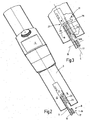
- FIG. 1 a thread measuring device 1 is illustrated, which has an oblong, while angled angled housing 2 with two housing sections 3, 4.
- the longer housing section 4 serves as a handle.
- a display 5 At its in use facing the user back is a display 5 and a control knob 10 is arranged.
- a displaceable or pivotally mounted release lever 6 At its facing away from the user front is a displaceable or pivotally mounted release lever 6 is arranged.
- This can be designed shell-shaped as a housing portion or housing part and, as will be made clearer later, for example, at the same time serve as a battery compartment lid.
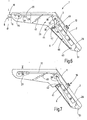
- the yarn gauge 1 has at the front free end 7 to a thread catcher 8, to which a pivotally mounted lever 9 belongs.
- the in FIG. 2 seen in plan view lever 9 is between two fork-like passage 11 limiting legs 12, 14 of the housing portion 3, 4 are arranged.
- the lever 9 carries at its free end 15 a thread guide element 16 in the form of a rotatably mounted thread roll 17, the axis of rotation 18 is aligned parallel to the pivot axis 19 of the lever 9 ( FIG. 3 ).
- the thread catcher 8 formed by the lever 9 is pivotable between two positions I, II, consisting of the FIGS. 4 and 5 emerge.
- the swivel angle ⁇ is preferably slightly less than 180 °.
- the position I is a catching position in which an imaginary connecting line between the axis of rotation 18 and the pivot axis 19 is approximately perpendicular to a thread 21 to be scanned.
- the other item II ( FIG. 5 ) is the measuring position in which the lever 9 abuts against a stop pin 22.
- a Diffleitelement 23 Concentric to the pivot axis 19 or in the immediate vicinity of the same a Ddenleitelement 23 is arranged in the form of a rotatably mounted thread roll 24, which has a thread groove as well as the thread roller 17.
- the thread grooves the thread rollers 17, 24 are how FIG. 3 illustrated, arranged in a common plane E, on which the pivot axis 19 and the rotation axis 18 are perpendicular.
- the thread roller 24 is connected to a rotary encoder 25. This emits electrical signals corresponding to the rotation of the thread roller 24.
- the rotary encoder 25 is connected to a not further illustrated processing device 26, for example, on from the FIGS. 6 and 7 apparent printed circuit board is housed in the form of a microcomputer.
- the processing device 26 is connected to the display 5, which is used for device setting, operation and the measured value display.
- a thread support element 27 is arranged in the form of a pin 28 which extends approximately parallel to the pivot axis 19 ( FIG. 3 ).
- the pin 28 projects with its free end into the passage 11 and is connected at its other end to a force sensor 29.
- the force sensor 29 and the pin 28 form a thread tension meter 31. This is connected to the processing device and sends electrical signals to them, which correspond to the detected thread tension.
- the pin 28 is arranged above a thread roller 24 with the thread roller 17 connecting tangent, so that the continuous thread 21 runs at an obtuse angle over the pin 28. The exact size of this angle is determined by the position of the stopper pin 22.
- the lever 9 is provided with a funnel-shaped cutout 32, which finds when pivoting the lever 9 in the measuring position on the pin 28 without touching it.
- FIGS. 6 and 7 illustrate an embodiment of the associated actuating mechanism 33 which connects the trigger lever 6 with the lever 9.
- To the actuating mechanism 33 includes a non-rotatably connected to the lever 9 gear 34, which meshes with an axially slidably mounted in the housing 2 rack 35.
- the rack 35 is connected at its other end to a gear 36 in connection, which is rotatably mounted in the housing 2.
- the gear 36 meshes with a gear 37 which is rotatably mounted, but rotatably connected to a lever 38.
- This has a hook-shaped end 39, which engages in the rest position with a nose-shaped projection 41 in an opening 42 of the trigger lever 6.
- This is constructed shell-shaped, wherein it has at its one end a laterally projecting pin or a similar projection for pivotal mounting in a slotted guide 43.
- the opening 42 is aligned approximately radially to the pivot axis defined by the slide guide 43, the in FIG. 6 is approximately perpendicular to the drawing plane.
- the lever 38 is arranged so that the projection 41 moves out of the opening 42 when the lever 6 is pressed onto the housing 2 and into this. In this case, a front wall 44 presses against the lever 38, even when the projection 41 has moved out of the opening 42.
- the release lever 6 with the lever 38 preferably includes a blunt or acute angle.
- the actuating mechanism 33 has a spring means.
- this may be formed by a tension spring 45, which biases the rack 35 in a selected longitudinal direction so that the lever 9 is biased to its catching position I out.
- the release lever 6 is designed as a battery compartment cover. It overarches an underlying battery compartment 46 by one or more batteries 47, 48 are arranged to power the processing device 26. They can be carried by the circuit board. This carries, for example, an additional switch 49 which activates the processing device.
- the actuating mechanism 33 preferably has a certain play or elasticity, which allows further depression of the trigger lever 6 to activate the switch 49 after the lever 9 has reached its measuring position II.
- the yarn gauge 1 described so far operates as follows:
- the yarn gauge 1 is turned on by pressing a button on the control knob 10. Alternatively or additionally, it can be provided to turn on the yarn gauge 1 by operating the release lever 6. Switching off the thread measuring device takes place automatically after a waiting time without further operation or alternatively by prolonged pressure on the control knob.
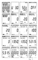
- the display 5 is in FIG. 9 top left with all display options illustrated. By turning and / or pressing the control knob 10 (depending on the embodiment), the three basic modes of measurement (MEASURE), memorization (MEM) and adjustment (SETUP) can be selected.
- the measuring menu is in FIG. 9 , left column, second line, illustrates. If it is activated, the measurement of the machine speed, the thread length, the thread tension and the thread speed can be selected.
- the second line of the FIG. 9 shows different displays, eg for average speed or for current speed (third and fourth column).
- the first line illustrates various settings (SETUP), for example for the selected unit (m / min, m, yd / min or inch).
- the thread length measurement can be selected in different modes ( FIG. 9 , third row, second column to fifth row, first column).
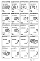
- the menus and displays of the thread tension display 5 are FIG. 9 , Row five, column 2 to FIG. 10 , Line three, column 2.
- the other indications concern the thread speed.
- the thread gauge When the desired measurement mode is selected, the thread gauge, such as FIG. 4 illustrated, brought to the thread until the thread roller 17, the thread 21 engages behind. Now, if the trigger lever 6 is actuated, the lever 9 works from its catching position I in its measuring position II, such as FIG. 5 illustrated. The lever 9 applies it to the stop pin 22 and thus finds a defined position. In this, the thread 21 passes over the pin 28, wherein on the force sensor 29, a force corresponding to the thread tension is registered. This is converted by the processing device into a thread tension value and displayed on the display 5 FIG. 9 or 10 , displayed. Depending on the selection, the average voltage, the peak voltage, the target voltage, the voltage deviation from this or the like can be displayed.
- the actual measurement is activated when the operating lever 6 is pressed firmly into the housing 2 after the lever 9 has already reached its measuring position II.
- the operating lever 6 then actuates the switch 49 to perform the measurement.
- the switch 49 In its previous lying position in which the lever 9 has reached the stop pin 22, the switch 49 is not yet actuated, the operating lever 6, if necessary, be locked by a slide not further illustrated.
- the printed circuit board or the processing device 26 arranged thereon can, like the FIGS. 6 and 7 be provided with an interface 51 in the form of a provided at the lower end of the housing 2 socket or a wireless radio link.
- the interface 51 serves for the input and output of signals (data).
- signals or data may represent the engine speed of a connected knitting machine or similar external data taken into account by the processing device. This allows, for example, the display of the engine speed, according to FIG. 9 , Column 2, line 2 to column 1, line 3.
- the provision of external data allows the calculation and display of related variables, such as the thread length per machine revolution ( Figure 9, column 2, line 3).
- data may be forwarded to an external device via the interface 51 as needed. This may be of particular interest when the yarn gauge 1 is used to scan a plurality of threads one after the other and to check them.
- the change of the batteries 47, 48 takes place as follows:
- the triggering lever 6 is pressed into the housing 2.
- the projection 41 moves out of the opening 42, so that no more locking and no other positive connection between the trigger lever 6 and the lever 38 is.
- the release lever 6 forming the battery compartment cover can not fall down because it is held by the fingers of the operator who must hold the release lever 6 against the force of the tension spring 45.
- the lever 9 is now held by hand, for example, in its measuring position, while the trigger lever 6 is released. He can because of the lever 38 in his, out FIG. 7 apparent deflected position remains, now be removed freely. This is off FIG. 8 seen.
- the battery compartment cover is installed in the opposite way.
- the lever 9 is transferred to measuring position II, after which the trigger lever 6 can be inserted into the opening of the battery compartment.
- the lever 38 hooks up with the release lever 6 and keeps it in place.
- the thread measuring device 1 is a hand-held measuring device with a thread catcher 8, which places the thread 21 over a thread support element 27 of a force sensor 29 when a release lever 6 is actuated.
- the device allows one-handed operation.
- the boomerang-shaped housing 2 is formed at one end as a handle on which both a release lever and a control knob 10, which is designed as a rotary-push button, as well as a display 5 is arranged.
- the control knob 10 can be rotated and pressed with the thumb of the operator, so that a complete operation, ie selection of all measurement and operating modes, only with the thumb is possible.
- the measurement is carried out by the release lever 6, which operates the thread catcher 8 and a Meß2011 istsschalter 49.
Landscapes
- Physics & Mathematics (AREA)
- General Physics & Mathematics (AREA)
- Chemical & Material Sciences (AREA)
- Analytical Chemistry (AREA)
- Force Measurement Appropriate To Specific Purposes (AREA)
- Spinning Or Twisting Of Yarns (AREA)
Abstract
Claims (14)
- Appareil de mesure de fil (1) pour des mesures manuelles, qui comporte :- un boîtier (2) équipé d'une poignée (4) et d'un organe d'actionnement (6),- un preneur de fil (8) présentant un levier qui porte à son extrémité libre un élément de guidage de fil (16) et qui peut, entre deux positions (I, II) dont l'une est une position de prise (I) et l'autre une position de mesure (II), basculer autour d'un axe de basculement (19), le basculement en position de mesure (II) étant effectué par un mécanisme d'actionnement (3) relié à l'organe d'actionnement (6),- un élément de guidage de fil (23) disposé en un endroit entre les deux positions (I, II) et qui est constitué par un galet de fil (24), relié à un encodeur (25) permettant de mesurer la vitesse d'un fil,- un appareil de mesure de tension de fil (31) disposé en un endroit entre la position de mesure (II) et l'élément de guidage de fil (23), la position de mesure (II) du preneur de fil (8) étant déterminée par un moyen de butée (22),- un dispositif de traitement (28) relié à l'appareil de mesure de tension (31) et à un dispositif d'affichage (5).
- Appareil de mesure de fil selon la revendication 1, caractérisé en ce que l'élément de guidage de fil (16) est un galet de fil (17) monté en rotation.
- Appareil de mesure de fil selon la revendication 1, caractérisé en ce qu'il présente, comme élément d'appui de fil (27), une broche (28) qui est essentiellement parallèle à l'axe de basculement (19) du levier (9) et qui est portée par un capteur de force (29).
- Appareil de mesure de fil selon la revendication 1, caractérisé en ce que le dispositif de traitement est relié à un contacteur de commande dont la tête de manoeuvre (10) est disposée sur la poignée (4).
- Appareil de mesure de fil selon la revendication 4, caractérisé en ce que le contacteur de commande est un bouton-poussoir rotatif.
- Appareil de mesure de fil selon la revendication 1, caractérisé en ce que le dispositif de traitement dispose, pour régler des modes de fonctionnement différents sur le dispositif d'affichage (5), d'une entrée pilotée par menu.
- Appareil de mesure de fil selon la revendication 1, caractérisé en ce que le dispositif de traitement (26) présente une interface (51) pour recevoir des signaux externes.
- Appareil de mesure de fil selon la revendication 1, caractérisé en ce que le dispositif de traitement (26) présente une interface (51) pour délivrer des signaux à un dispositif externe.
- Appareil de mesure de fil selon la revendication 1, caractérisé en ce que le boîtier (2) présente deux branches allongées (3, 4) faisant entre elles un angle obtus.
- Appareil de mesure de fil selon la revendication 9, caractérisé en ce que la branche (3) présente à son extrémité libre (7) le preneur de fil (8) tandis que l'autre branche (4) sert de poignée.
- Appareil de mesure de fil selon la revendication 1, caractérisé en ce dans la poignée se trouve une chambre de piles (46) pour accueillir au moins une pile d'alimentation (47, 48).
- Appareil de mesure de fil selon la revendication 11, caractérisé en ce que la chambre de piles (46) possède un couvercle de fermeture qui sert en même temps d'organe d'actionnement (8).
- Appareil de mesure de fil selon la revendication 12, caractérisé en ce que le mécanisme d'actionnement (39), par un verrou (41) est en prise verrouillée par combinaison de formes, avec l'organe d'actionnement (6) non activé, pour sécuriser la position de cet organe.
- Appareil de mesure de fil selon la revendication 13, caractérisé en ce que le verrou (41), quand l'organe d'actionnement (6) est activé, se déplace perpendiculairement à une partie (44) de cet organe (6), pour le déverrouiller.
Applications Claiming Priority (3)
| Application Number | Priority Date | Filing Date | Title |
|---|---|---|---|
| DE10257997A DE10257997B4 (de) | 2002-12-12 | 2002-12-12 | Fadenmessgerät, insbesondere für instationäre Anwendungen |
| DE10257997 | 2002-12-12 | ||
| PCT/EP2003/013418 WO2004052765A1 (fr) | 2002-12-12 | 2003-11-28 | Appareil de mesure de fil, destine notamment a des applications non stationnaires |
Publications (2)
| Publication Number | Publication Date |
|---|---|
| EP1575859A1 EP1575859A1 (fr) | 2005-09-21 |
| EP1575859B1 true EP1575859B1 (fr) | 2008-03-26 |
Family
ID=32477570
Family Applications (1)
| Application Number | Title | Priority Date | Filing Date |
|---|---|---|---|
| EP03795851A Expired - Lifetime EP1575859B1 (fr) | 2002-12-12 | 2003-11-28 | Appareil de mesure de fil, destine notamment a des applications non stationnaires |
Country Status (8)
| Country | Link |
|---|---|
| US (1) | US7475490B2 (fr) |
| EP (1) | EP1575859B1 (fr) |
| KR (1) | KR100748869B1 (fr) |
| CN (1) | CN100339286C (fr) |
| AU (1) | AU2003298147A1 (fr) |
| DE (2) | DE10257997B4 (fr) |
| TW (1) | TWI244460B (fr) |
| WO (1) | WO2004052765A1 (fr) |
Families Citing this family (8)
| Publication number | Priority date | Publication date | Assignee | Title |
|---|---|---|---|---|
| DE102005038047B4 (de) * | 2005-08-10 | 2008-02-07 | Gerhard Schnebel | Fadenspannungssensor |
| US7458170B1 (en) * | 2006-02-17 | 2008-12-02 | Richardson Shane D | Automatic cord length measuring device |
| GB0608994D0 (en) * | 2006-05-05 | 2006-06-14 | Inneva Ltd | Tension monitor |
| US7717834B2 (en) * | 2007-06-12 | 2010-05-18 | Kay Scott A | Therapeutic shoulder apparatus |
| US20100007186A1 (en) * | 2008-07-14 | 2010-01-14 | Strong L Curtis | Tension indicator |
| CN103383294A (zh) * | 2013-06-26 | 2013-11-06 | 江苏中新资源集团有限公司 | 一种纱线张力检测器 |
| CN112033653B (zh) * | 2020-08-17 | 2022-05-10 | 南方科技大学 | 测量仪 |
| DE102021002646A1 (de) | 2021-05-20 | 2022-11-24 | Oerlikon Textile Gmbh & Co. Kg | Verfahren zur Überwachung einer Vielzahl von Bearbeitungsstellen für synthetische Fäden |
Family Cites Families (11)
| Publication number | Priority date | Publication date | Assignee | Title |
|---|---|---|---|---|
| US2456150A (en) * | 1945-01-01 | 1948-12-14 | Garold N Rowley | Grinding apparatus with upper gyratory drive |
| US2472142A (en) * | 1946-11-08 | 1949-06-07 | Boulin Instr Corp | Tensiometer |
| US2564150A (en) * | 1949-03-14 | 1951-08-14 | Clemson Agricultural College O | Tensiometer |
| US3962730A (en) * | 1974-04-17 | 1976-06-15 | Dennison Manufacturing Company | Removal of faulty material in the manufacture of non-metallic webs |
| US3992936A (en) * | 1975-06-23 | 1976-11-23 | Wesco Industries Corporation | Yarn measuring instrument |
| US4092857A (en) * | 1977-07-05 | 1978-06-06 | Lawson-Hemphill, Inc. | Tensiometer |
| US4245512A (en) * | 1979-06-18 | 1981-01-20 | Levi Strauss & Co. | Fabric stretch testing device |
| WO1995033671A2 (fr) * | 1994-06-06 | 1995-12-14 | Barmag-Spinnzwirn Gmbh | Bobineuse pour fil achemine a vitesse constante |
| DE19635695A1 (de) * | 1996-09-03 | 1998-03-05 | Schlafhorst & Co W | Fadenführungseinrichtung |
| DE10025046B4 (de) * | 1999-05-28 | 2007-12-27 | Toray Engineering Co., Ltd. | Vorrichtung zum Erfassen der Garnspannung und Garnsensor |
| CH694407A5 (de) * | 2000-01-19 | 2004-12-31 | Zitec Ag | Fadenspannungsmesser. |
-
2002
- 2002-12-12 DE DE10257997A patent/DE10257997B4/de not_active Expired - Fee Related
-
2003
- 2003-11-28 WO PCT/EP2003/013418 patent/WO2004052765A1/fr not_active Ceased
- 2003-11-28 EP EP03795851A patent/EP1575859B1/fr not_active Expired - Lifetime
- 2003-11-28 AU AU2003298147A patent/AU2003298147A1/en not_active Abandoned
- 2003-11-28 CN CNB2003801055571A patent/CN100339286C/zh not_active Expired - Fee Related
- 2003-11-28 US US10/538,430 patent/US7475490B2/en not_active Expired - Fee Related
- 2003-11-28 KR KR1020057010596A patent/KR100748869B1/ko not_active Expired - Fee Related
- 2003-11-28 DE DE50309502T patent/DE50309502D1/de not_active Expired - Lifetime
- 2003-12-11 TW TW092134948A patent/TWI244460B/zh not_active IP Right Cessation
Also Published As
| Publication number | Publication date |
|---|---|
| DE50309502D1 (de) | 2008-05-08 |
| DE10257997A1 (de) | 2004-07-15 |
| DE10257997B4 (de) | 2005-11-24 |
| WO2004052765A1 (fr) | 2004-06-24 |
| KR20050085540A (ko) | 2005-08-29 |
| CN1723166A (zh) | 2006-01-18 |
| TW200502152A (en) | 2005-01-16 |
| CN100339286C (zh) | 2007-09-26 |
| EP1575859A1 (fr) | 2005-09-21 |
| US20080022544A1 (en) | 2008-01-31 |
| AU2003298147A1 (en) | 2004-06-30 |
| TWI244460B (en) | 2005-12-01 |
| US7475490B2 (en) | 2009-01-13 |
| KR100748869B1 (ko) | 2007-08-13 |
Similar Documents
| Publication | Publication Date | Title |
|---|---|---|
| EP0133557B1 (fr) | Clé à cliquet pour serrer des vis | |
| EP0266713B1 (fr) | Dispositif pour mesurer des distances à partir d'une pièce d'oeuvre et pied à coulisse pourvu de mesure digitale de ces distances | |
| EP1575859B1 (fr) | Appareil de mesure de fil, destine notamment a des applications non stationnaires | |
| WO2005058092A1 (fr) | Element mobilier mobile | |
| EP0021388B1 (fr) | Dispositif pour découper des bandes verticales de papier | |
| DE4435893C1 (de) | Handmeßgerät für densitometrische und farbmetrische Reflexionsmessungen | |
| DE102018116482B4 (de) | Rollmaßband mit ausfahrbarer Spann- und Messvorrichtung | |
| DE3724137C2 (de) | Elektronisches Meßgerät mit Digitalanzeige | |
| WO2004058032A1 (fr) | Aspirateur comportant un dispositif auxiliaire d'extraction de cable electrique | |
| DE2557593C3 (de) | Fadenfang- und - anlegevorrichtung | |
| EP0556590B1 (fr) | Procédé et dispositif pour la détermination de l'identité d'une clé-ébauche | |
| DE102008055581A1 (de) | Drehmomentschlüssel mit veränderbarem Arbeitswinkel | |
| DE2920161C2 (de) | Vorrichtung für die Winkeleinstellung der Lineale bei einem Zeichenkopf | |
| DE3111980C2 (de) | Mikrometer | |
| WO2012163921A1 (fr) | Capteur d'angle de pliage | |
| DE3717912A1 (de) | Anbringstellenindikator | |
| EP2980000B1 (fr) | Dispositif de sortie de papier | |
| DE1908880A1 (de) | Durch einen Ausloeser betaetigte Schaltvorrichtung mit einer Stelleinrichtung fuer die Bewirkung mehrerer bestimmter Stellungen des Ausloesers | |
| DE2642069A1 (de) | Vorrichtung zum laengstransport einmalig verwendbarer farb- oder loeschbaender in kraftangetriebenen schreib- oder aehnlichen bueromaschinen | |
| CH694407A5 (de) | Fadenspannungsmesser. | |
| CH432233A (de) | Kamera mit Belichtungsmess- oder -steuereinrichtung | |
| DE19643201A1 (de) | Fernbedienungsgeber | |
| DE1573430C (de) | Härteprüfer | |
| DE2165722C3 (de) | Bandzuggesteuerte Band-Stop-Einrichtung für Kassetten-Tonbandgeräte | |
| DE1955439C3 (de) | Drucktastenschalteinrichtung zum Fortschalten von Ziffernrollen |
Legal Events
| Date | Code | Title | Description |
|---|---|---|---|
| PUAI | Public reference made under article 153(3) epc to a published international application that has entered the european phase |
Free format text: ORIGINAL CODE: 0009012 |
|
| 17P | Request for examination filed |
Effective date: 20050520 |
|
| AK | Designated contracting states |
Kind code of ref document: A1 Designated state(s): AT BE BG CH CY CZ DE DK EE ES FI FR GB GR HU IE IT LI LU MC NL PT RO SE SI SK TR |
|
| AX | Request for extension of the european patent |
Extension state: AL LT LV MK |
|
| DAX | Request for extension of the european patent (deleted) | ||
| RBV | Designated contracting states (corrected) |
Designated state(s): DE IT TR |
|
| 17Q | First examination report despatched |
Effective date: 20070612 |
|
| GRAP | Despatch of communication of intention to grant a patent |
Free format text: ORIGINAL CODE: EPIDOSNIGR1 |
|
| GRAS | Grant fee paid |
Free format text: ORIGINAL CODE: EPIDOSNIGR3 |
|
| GRAA | (expected) grant |
Free format text: ORIGINAL CODE: 0009210 |
|
| AK | Designated contracting states |
Kind code of ref document: B1 Designated state(s): DE IT TR |
|
| RIN1 | Information on inventor provided before grant (corrected) |
Inventor name: MUEHLBERG, KARL-HEINZ Inventor name: SAWALL, ROLF-REINER Inventor name: WOERNER, CHRISTOPH |
|
| REF | Corresponds to: |
Ref document number: 50309502 Country of ref document: DE Date of ref document: 20080508 Kind code of ref document: P |
|
| PLBE | No opposition filed within time limit |
Free format text: ORIGINAL CODE: 0009261 |
|
| STAA | Information on the status of an ep patent application or granted ep patent |
Free format text: STATUS: NO OPPOSITION FILED WITHIN TIME LIMIT |
|
| 26N | No opposition filed |
Effective date: 20081230 |
|
| PGFP | Annual fee paid to national office [announced via postgrant information from national office to epo] |
Ref country code: IT Payment date: 20121123 Year of fee payment: 10 Ref country code: TR Payment date: 20121121 Year of fee payment: 10 |
|
| PGFP | Annual fee paid to national office [announced via postgrant information from national office to epo] |
Ref country code: DE Payment date: 20130122 Year of fee payment: 10 |
|
| PG25 | Lapsed in a contracting state [announced via postgrant information from national office to epo] |
Ref country code: IT Free format text: LAPSE BECAUSE OF NON-PAYMENT OF DUE FEES Effective date: 20131128 Ref country code: DE Free format text: LAPSE BECAUSE OF NON-PAYMENT OF DUE FEES Effective date: 20140603 |
|
| REG | Reference to a national code |
Ref country code: DE Ref legal event code: R119 Ref document number: 50309502 Country of ref document: DE Effective date: 20140603 |
|
| PG25 | Lapsed in a contracting state [announced via postgrant information from national office to epo] |
Ref country code: TR Free format text: LAPSE BECAUSE OF NON-PAYMENT OF DUE FEES Effective date: 20131128 |