EP1575708B1 - Grinding machine for all kinds of material, e.g. waste or wood - Google Patents
Grinding machine for all kinds of material, e.g. waste or wood Download PDFInfo
- Publication number
- EP1575708B1 EP1575708B1 EP03775058A EP03775058A EP1575708B1 EP 1575708 B1 EP1575708 B1 EP 1575708B1 EP 03775058 A EP03775058 A EP 03775058A EP 03775058 A EP03775058 A EP 03775058A EP 1575708 B1 EP1575708 B1 EP 1575708B1
- Authority
- EP
- European Patent Office
- Prior art keywords
- cutting
- tools
- comminution
- shaft
- rigid
- Prior art date
- Legal status (The legal status is an assumption and is not a legal conclusion. Google has not performed a legal analysis and makes no representation as to the accuracy of the status listed.)
- Expired - Lifetime
Links
- 239000000463 material Substances 0.000 title claims abstract description 63
- 239000002023 wood Substances 0.000 title claims description 7
- 239000002699 waste material Substances 0.000 title claims description 5
- 238000005520 cutting process Methods 0.000 claims abstract description 122
- 238000000034 method Methods 0.000 claims abstract description 14
- 230000008569 process Effects 0.000 claims abstract description 14
- 230000000694 effects Effects 0.000 claims abstract description 9
- 239000010782 bulky waste Substances 0.000 claims description 6
- 230000009471 action Effects 0.000 claims description 5
- 239000010791 domestic waste Substances 0.000 claims description 4
- 239000010815 organic waste Substances 0.000 claims description 3
- 229910000831 Steel Inorganic materials 0.000 claims 2
- 239000010959 steel Substances 0.000 claims 2
- WYTGDNHDOZPMIW-RCBQFDQVSA-N alstonine Natural products C1=CC2=C3C=CC=CC3=NC2=C2N1C[C@H]1[C@H](C)OC=C(C(=O)OC)[C@H]1C2 WYTGDNHDOZPMIW-RCBQFDQVSA-N 0.000 claims 1
- 239000010813 municipal solid waste Substances 0.000 claims 1
- 238000010008 shearing Methods 0.000 claims 1
- 206010041953 Staring Diseases 0.000 description 11
- 241001295925 Gegenes Species 0.000 description 5
- 238000007789 sealing Methods 0.000 description 5
- 238000005265 energy consumption Methods 0.000 description 4
- 230000005540 biological transmission Effects 0.000 description 2
- 230000000875 corresponding effect Effects 0.000 description 2
- 230000002349 favourable effect Effects 0.000 description 2
- 230000003993 interaction Effects 0.000 description 2
- 238000012423 maintenance Methods 0.000 description 2
- 238000004519 manufacturing process Methods 0.000 description 2
- 230000008439 repair process Effects 0.000 description 2
- 238000003860 storage Methods 0.000 description 2
- 230000000712 assembly Effects 0.000 description 1
- 238000000429 assembly Methods 0.000 description 1
- 230000004927 fusion Effects 0.000 description 1
- 230000001976 improved effect Effects 0.000 description 1
- 230000006872 improvement Effects 0.000 description 1
- 239000002655 kraft paper Substances 0.000 description 1
- 230000004048 modification Effects 0.000 description 1
- 238000012986 modification Methods 0.000 description 1
- 239000004033 plastic Substances 0.000 description 1
- 239000002985 plastic film Substances 0.000 description 1
- 229920006255 plastic film Polymers 0.000 description 1
- 230000009467 reduction Effects 0.000 description 1
- 210000002023 somite Anatomy 0.000 description 1
- 230000003319 supportive effect Effects 0.000 description 1
Images
Classifications
-
- B—PERFORMING OPERATIONS; TRANSPORTING
- B02—CRUSHING, PULVERISING, OR DISINTEGRATING; PREPARATORY TREATMENT OF GRAIN FOR MILLING
- B02C—CRUSHING, PULVERISING, OR DISINTEGRATING IN GENERAL; MILLING GRAIN
- B02C18/00—Disintegrating by knives or other cutting or tearing members which chop material into fragments
- B02C18/06—Disintegrating by knives or other cutting or tearing members which chop material into fragments with rotating knives
- B02C18/16—Details
- B02C18/18—Knives; Mountings thereof
- B02C18/182—Disc-shaped knives
-
- B—PERFORMING OPERATIONS; TRANSPORTING
- B02—CRUSHING, PULVERISING, OR DISINTEGRATING; PREPARATORY TREATMENT OF GRAIN FOR MILLING
- B02C—CRUSHING, PULVERISING, OR DISINTEGRATING IN GENERAL; MILLING GRAIN
- B02C18/00—Disintegrating by knives or other cutting or tearing members which chop material into fragments
- B02C18/06—Disintegrating by knives or other cutting or tearing members which chop material into fragments with rotating knives
- B02C18/14—Disintegrating by knives or other cutting or tearing members which chop material into fragments with rotating knives within horizontal containers
- B02C18/142—Disintegrating by knives or other cutting or tearing members which chop material into fragments with rotating knives within horizontal containers with two or more inter-engaging rotatable cutter assemblies
-
- B—PERFORMING OPERATIONS; TRANSPORTING
- B02—CRUSHING, PULVERISING, OR DISINTEGRATING; PREPARATORY TREATMENT OF GRAIN FOR MILLING
- B02C—CRUSHING, PULVERISING, OR DISINTEGRATING IN GENERAL; MILLING GRAIN
- B02C18/00—Disintegrating by knives or other cutting or tearing members which chop material into fragments
- B02C18/06—Disintegrating by knives or other cutting or tearing members which chop material into fragments with rotating knives
- B02C18/16—Details
- B02C18/18—Knives; Mountings thereof
- B02C2018/188—Stationary counter-knives; Mountings thereof
Landscapes
- Engineering & Computer Science (AREA)
- Food Science & Technology (AREA)
- Crushing And Pulverization Processes (AREA)
- Debarking, Splitting, And Disintegration Of Timber (AREA)
- Finish Polishing, Edge Sharpening, And Grinding By Specific Grinding Devices (AREA)
- Disintegrating Or Milling (AREA)
- Polysaccharides And Polysaccharide Derivatives (AREA)
- Shovels (AREA)
Abstract
Description
Die Erfindung betrifft eine Zerkleinerungsmaschine für Material beliebiger Art, z. B. Abfall, wie Hausmüll und Sperrmüll oder Holz, aufweisend eine in einem Gehäuse vorgesehene Aufnahme für das Material, mindestens eine angetriebene Welle, auf der Zerkleinerungswerkzeuge vorgesehen sind und im Gehäuse angeordnete starre Schneidwerkzeuge als Gegenwerkzeuge für die Zerkleinerungswerkzeuge zur Zerkleinerung des Materials, mit den im Oberbegriff des Anspruchs 1 angegebenen Merkmalen.The invention relates to a crushing machine for material of any kind, for. B. waste, such as household waste and bulky waste or wood, comprising a housing provided in a receptacle for the material, at least one driven shaft, are provided on the crushing tools and arranged in the housing rigid cutting tools as counter tools for crushing tools for crushing the material with the in the preamble of
Derartige Zerkleinerungsmaschinen sind unter der Bezeichnung "Zerreißer" bekannt geworden.Such crushers have become known under the name "ripper".
Nach der Zusammenschau des Standes der Technik lässt sich für die eingangs nur gattungsmäßig umrissene Zerkleinerungsmaschine eine Vorrichtung zusammenstellen, die nachstehend beschriebene Merkmalsgruppen aufweist.According to the synopsis of the prior art, it is possible to assemble a device having the feature groups described below for the shredding machine, which is initially only generically outlined.
Entsprechend der EP 0 521 081 B1 sind bekannterweise die Zerkleinerungswerkzeuge aus U-förmigen Messern gebildet, die in einer zur Drehachse für die Wellen senkrechten Ebene liegen und die gleichmäßig entlang und rund um zwei im wesentlichen parallele und horizontale Wellen, die von einem Motor angetrieben werden, der die Wellen in entgegengesetzten Richtungen antreiben kann, und die einen gegenseitigen Abstand aufweisen, der etwas größer als der doppelte Abstand zwischen dem radialen Außenpunkt eines Messers und der Drehachse ist, angeordnet sind. Die Antriebsvorrichtungen sind zwischen dem Motor und den Wellen vorgesehen.According to EP 0 521 081 B1, the comminution tools are known to consist of U-shaped knives lying in a plane perpendicular to the axis of rotation of the shafts and uniformly along and around two substantially parallel and horizontal shafts driven by a motor which can drive the shafts in opposite directions and which have a mutual distance which is slightly greater than twice the distance between the radial outside point of a blade and the axis of rotation. The drive devices are provided between the motor and the shafts.
Das Material wird den Messern durch einen über den Messern angeordneten Schacht zugeführt. Diese Messer arbeiten mit zwischen den Wellen auf einem Teil des Rahmens der Vorrichtung zur Materialzerkleinerung feststehend angebrachten Messern zusammen, wenn die Wellen in entgegengesetzten Richtungen rotieren, wodurch die Schnittkante der Blätter an der Oberseite der feststehenden Messer aufeinander zu bewegt werden.The material is fed to the knives through a shaft arranged above the knives. These knives cooperate with knives fixedly mounted between the shafts on a portion of the frame of the material shredding device as the shafts rotate in opposite directions, thereby moving the cut edge of the sheets at the top of the fixed knives towards each other.
Dazu ist, wie auch aus älterem Stand der Technik vorbekannt, der gegenseitige Abstand zwischen den zwei Wellen ein fester Abstand.For this purpose, as also known from the prior art, the mutual distance between the two waves a fixed distance.
Die Antriebseinrichtungen umfassen ebenfalls in vorbekannter Weise ein geeignetes Getriebe für jede der zwei Wellen, einen hydraulischen Motor mit einstellbaren Rotationsgeschwindigkeiten zum Betreiben jeder Welle, eine einstellbare Pumpe zum Versorgen jedes hydraulischen Motors und Getriebes, durch die der Motor die Pumpen betreibt, die den Fluss durch die hydraulischen Motoren umzukehren vermögen, um jede Welle individuell vorwärts und rückwärts gemäß einer vorbestimmten Sequenz zu drehen.The drive means also comprise, as previously known, a suitable transmission for each of the two shafts, a hydraulic motor with adjustable rotational speeds for operating each shaft, an adjustable pump for supplying each hydraulic motor and transmission through which the motor operates the pumps, which transmits the flow reversing the hydraulic motors to rotate each shaft individually forward and backward in accordance with a predetermined sequence.
Als wesentlich ist nun der Erfindung gemäß der EP 0 521 081 B1 zu entnehmen, dass jedes Messer zwei hintereinander angeordnete und im wesentlichen U-förmige Blätter umfasst, dass die radial äußeren und vorderen Teile der zwei Blätter, in der Rotationsrichtung der Schneidebewegung der Messer gesehen, als im wesentlichen tangential orientierte Keile gebaut sind, dass der Abstand zwischen der Rotationsachse und dem Keil des vorderen Blatts kürzer als der Abstand zwischen der Rotationsachse und dem Keil des nachfolgenden Blatts ist und dass die radial äußere Kontur des nachfolgenden Blatts im wesentlichen einem Segment einer spiralförmigen Linie um die Rotationsachse entspricht.As essential now is to be inferred from the invention according to EP 0 521 081 B1 that each knife comprises two successively arranged and substantially U-shaped blades, that the radially outer and front parts of the two leaves, seen in the direction of rotation of the cutting movement of the knife are constructed as substantially tangentially oriented wedges, that the distance between the axis of rotation and the wedge of the front blade is shorter than the distance between the axis of rotation and the wedge of the succeeding blade and that the radially outer contour of the succeeding blade substantially a segment of a spiral line around the axis of rotation corresponds.
Hierzu können in funktioneller Kombination die Merkmale der gattungsgleichen Zerkleinerungsmaschine entsprechend der EP 0 928 222 B1 ergänzt werden, um eine funktionierende Einheit zu erhalten.For this purpose, the features of the same type comminution machine according to EP 0 928 222 B1 can be supplemented in functional combination in order to obtain a functioning unit.
Demzufolge sind die feststehenden Messer durch einen vorbekannten Schneidtisch gebildet, der am Boden eines Trichters mit wenigstens einem Satz fixierter; paralleler unterer Messer angeordnet ist, welche voneinander durch Öffnungen durch den Tisch getrennt sind.Accordingly, the fixed knives are formed by a prior art cutting table fixed to the bottom of a funnel with at least one set; arranged parallel lower knife, which are separated from each other by openings through the table.
Weiterhin ist in bekannter Art wenigstens eine drehbare Welle einer Antriebseinheit vorgesehen, welche Welle über dem Schneidtisch in einer Richtung angeordnet ist, die sich senkrecht zu den unteren Messern erstreckt.Furthermore, in a known manner at least one rotatable shaft of a drive unit is provided, which shaft is arranged above the cutting table in a direction which extends perpendicular to the lower blades.
Schließlich sind bekannterweise eine Anzahl von scheibenförmigen oberen Messern vorhanden, die an der Welle befestigt sind, von denen jedes Messer mit einer Anzahl von Zähnen versehen ist und die sich teilweise nach unten in jede ihrer Öffnungen des Tischs erstreckt. Jede Öffnung ist breiter als das zugehörige obere Messer, welches außerdem nahe einem der unteren Messer in der zugehörigen Öffnung angeordnet ist.Finally, there are known to be a number of disc-shaped upper knives mounted on the shaft, each knife being provided with a number of teeth and extending partially downwardly into each of its openings in the table. Each opening is wider than the associated upper knife, which is also located near one of the lower knives in the associated opening.
Nach der dort offenbarten Erfindung ist es wesentlich, dass die unteren Messer sich in eine Richtung erstrecken, die die Achse der Welle oder einen Bereich um diese herum schneidet, wobei zu dieser Ausführung davon ausgegangen wird, dass gemäß DK 169 378 schon ein Schneidtisch bekannt ist, dessen Ebene sich schon unterhalb der Welle erstreckt.According to the invention disclosed there, it is essential that the lower knives extend in a direction intersecting the axis of the shaft or a region around it, it being assumed for this embodiment that according to DK 169 378 a cutting table is already known whose plane already extends below the shaft.
Dabei ist auf jeder Seite der Welle ein Satz mehrer Messer angeordnet, deren Anordnung zueinander ein V oder ein umgekehrtes V bilden.In this case, a set of several blades is arranged on each side of the shaft, the arrangement of which form a V or an inverted V to each other.
Die jeweiligen Schneidkanten können gewölbt oder wellenförmig ausgeführt sein.The respective cutting edges may be curved or wave-shaped.
Durch die konstruktive Verbesserung nach der EP 0 928 222 B1 des in Messer aufgeteilten Schneidtisches, in dem die Ebene des Schneidtisches die Achse der Welle schneidet, soll mit einem vorteilhaften Schneidwinkel von ca. 90° das Material zerkleinert werden.Due to the design improvement according to EP 0 928 222 B1 of the cutting table divided into knives, in which the plane of the cutting table intersects the axis of the shaft, the material is to be comminuted with an advantageous cutting angle of approximately 90 °.
Eine nach dem dokumentierten Stand der Technik so zusammengestellte und vorstehend beschriebene Zerkleinerungsmaschine für Materialien, wie organischen Abfall, sperrigen Abfall oder dergleichen weist trotz bewährter Funktion noch Nachteile auf, die insbesondere darin bestehen, dass
- die auf der Welle angebrachten Zerkleinerungswerkzeuge in ihrer Stabilität gefährdet sind,
- der Zerkleinerungsprozess durch die feststehenden Messer in seiner Effektivität begrenzt ist,
- der Durchsatz infolge der das Material wegdrückenden Wirkung der Form der Zerkleinerungswerkzeuge auf der Welle im Zusammenspiel mit den feststehenden Messern nicht steigerbar ist und
- der Energieverbrauch der Maschine relativ hoch ist.
- the crushing tools mounted on the shaft are endangered in their stability,
- the crushing process is limited in its effectiveness by the fixed knives,
- the throughput due to the material wegdrückenden effect of the shape of the crushing tools on the shaft in combination with the fixed blades is not increasable and
- the energy consumption of the machine is relatively high.
Die Erfindung stellt sich die Aufgabe, eine Zerkleinerungsmaschine für Material beliebiger Art, z. B. Abfall, wie Hausmüll und Sperrmüll oder Holz, insbesondere organischer Abfall, sperriger Abfall, wie Kühlschränke, Reifen, Möbel, Teppiche, Matratzen, Baumstümpfe, Abbruchholz oder dergleichen Materialien zu schaffen, die umfasst
- eine in einem Gehäuse vorgesehene Aufnahme für das Material,
- mindestens eine Welle, auf der Zerkleinerungswerkzeuge angeordnet sind,
- im Gehäuse angebrachte starre Schneidwerkzeuge, deren Schneidkanten in ihrer Verlängerung gerade nicht die Achse der Welle oder einen Bereich um die Achse herum schneiden, gegen welche starren Schneidwerkzeuge die Zerkleinerungswerkzeuge der Welle das aufgegebene Material schneiden.
Damit soll im Zusammenspiel der in beiden Drehrichtungen wirkenden Zerkleinerungswerkzeuge mit den starren Schneidwerkzeugen der Abfall stets differenziert erfasst, gefördert und fixiert gegen die starren Schneidwerkzeuge mit spezifisch geringen Kräften zerkleinert werden.
Einerseits muss die Zerkleinerungsmaschine für die Herstellung, den Betrieb, die Wartung und Reparatur in dafür geeignete Baugruppen gestaltet werden und andererseits für die Bedingungen des Zerkleinerungsprozesses steuerbar sein.
Im Ergebnis der zu lösenden Aufgabe sind - die Stabilität der Zerkleinerungswerkzeuge der Welle zu erhöhen,
- der Zerkleinerungsgrad durch konstruktive Veränderung der starren Schneidwerkzeuge zu steigern,
- die Durchsatzleistung der Maschine zu erhöhen,
- der Energieverbrauch der Maschine zu senken,
- die Zerkleinerbarkeit von insbesondere duktileren, nicht sprödbrüchigen Materialien wie z. B. Plastik und Plastikfolien zu fördern und
- das im Aufnahmebereich vorliegende und direkt zu zerkleinernde Material den verfügbaren Schneidgeometrien vollständig zuzuführen
- a housing provided in a housing for the material,
- at least one shaft on which comminution tools are arranged,
- mounted in the housing rigid cutting tools whose cutting edges just do not cut the axis of the shaft or an area around the axis in their extension, against which rigid cutting tools the crushing tools of the shaft cut the discontinued material.
In order for the waste to be always detected differentiated, promoted and fixed against the rigid cutting tools with specific low forces in the interaction of acting in both directions crushing tools with the rigid cutting tools.
On the one hand, the crusher for manufacturing, operation, maintenance and repair must be designed in suitable assemblies and on the other hand controllable for the conditions of the crushing process.
As a result of the problem to be solved - to increase the stability of the crushing tools of the shaft,
- to increase the degree of comminution by constructive modification of the rigid cutting tools,
- to increase the throughput of the machine,
- to reduce the energy consumption of the machine,
- the comminution of particularly ductile, non-brittle materials such. B. to promote plastic and plastic films and
- to completely feed the material available in the receiving area and directly to be comminuted to the available cutting geometries
Erfindungsgemäß wird dies dadurch gelöst, dass
- a) die Zerkleinerungswerkzeuge in jeweils einer Drehrichtung der Welle und in deren Querschnitt gesehen mindestens zwei Schneidenbereiche aufweist, von denen mindestens ein innerer Schneidenbereich mehr zu zerkleinerndes Material erfassen und zerkleinern kann und dafür einen relativ kleinen Hebelarm besitzt, sowie mindestens ein äußerer Schneidenbereich weniger zu zerkleinerndes Material erfassen und zerkleinern kann und dafür einen relativ großen Hebelarm besitzt, wobei die Schneidenkonturen beider Schneidenbereiche in Richtung der Achse der Welle einen Kreisbogen um die Achse der Welle bilden,
- b) die starren Schneidwerkzeuge mehrere sägeartig angeordnete Zähne aufweisen und somit zwei im Winkel zueinander stehende Zahnflanken der Zähne mit einem der Schneidenbereiche zusammenarbeiten,
- c) in jeder beginnenden wirksamen Schneidstellung eine, eine erste Querschneide bildende Spitze der Zerkleinerungswerkzeuge gegen eine, eine zweite Querschneide bildende Spitze eines Zahnes der starren Schneidwerkzeuge parallelversetzt und vorbeischneidend gerichtet ist, wodurch die neben der zwischen dem Schneidenbereichen der Zerkleinerungswerkzeuge und den Schneidkanten der starren Schneidwerkzeuge erzeugten Schneidkräfte eine zusätzliche sowie parallel zur Achse der Welle gerichtete Brechkante mit auf das Material parallelversetzter Kerbwirkung und spezifisch hoch wirkender Kraft erhalten ist und
- d) das Material unter aggressiver Teilnahme der Zähne der starren Schneidwerkzeuge einem aktiven und zusätzlichen Zerkleinerungsvorgang unterworfen ist.
- a) the crushing tools seen in each case a direction of rotation of the shaft and in its cross section has at least two cutting areas, of which at least one inner cutting area can detect and crush more material to be shredded and has a relatively small lever arm, and at least one outer cutting area less to shred Gripping and chopping material and having a relatively large lever arm, the cutting contours of both cutting regions in the direction of the axis of the shaft forming a circular arc about the axis of the shaft,
- b) the rigid cutting tools have a plurality of serrated teeth and thus cooperate two mutually angled tooth flanks of the teeth with one of the cutting areas,
- c) in each beginning effective cutting position, a, forming a first transverse cutting tip of the crushing tools against a, a second transverse cutting edge forming tip of a tooth of the rigid cutting tools is offset parallel and vorbeischneidend, whereby the cutting forces generated in addition to the between the cutting areas of the crushing tools and the cutting edges of the rigid cutting tools an additional and parallel to the axis of the shaft refractive edge with the material parallel offset notch effect and specific high-acting Power is received and
- d) the material is subjected to an active and additional comminution process with aggressive participation of the teeth of the rigid cutting tools.
In weiterer Ausbildung der Erfindung sind die Zerkleinerungswerkzeuge in axialer Richtung auf der Welle zueinander versetzt oder in einem unterschiedlichen radialen Abstand angeordnet, wobei dementsprechend auch die Zähne auf den starren Schneidwerkzeugen angeordnet sind, welche Schneidwerkzeuge als sogenannte Bramme verlaufen.In a further embodiment of the invention, the crushing tools are offset in the axial direction on the shaft to each other or arranged at a different radial distance, and accordingly the teeth are arranged on the rigid cutting tools, which cutters run as a so-called slab.
Des weiteren weist die Welle Scheiben auf, an denen die Zerkleinerungswerkzeuge angeordnet oder ausgebildet sind. Diese Zerkleinerungswerkzeuge arbeiten, und zwar zwischen die auf Abstand angeordneten starren Schneidwerkzeuge der Bramme kämmend, mit den Zähnen zusammen.Furthermore, the shaft has discs on which the comminution tools are arranged or formed. These crushing tools work, meshing with the teeth between the spaced-apart rigid cutting tools of the slab.
Um die Welle günstig montieren und demontieren zu können, weist sie an beiden Seiten Zapfen auf, die lösbar mit der Welle verbunden sind und ggf. einen Lagerbereich bilden. Dabei kann die Verbindung so gestaltet werden, dass sie mittels Flansche erfolgt.In order to mount the shaft cheap and dismantle, it has on both sides pins, which are detachably connected to the shaft and possibly form a storage area. In this case, the connection can be designed so that it takes place by means of flanges.
Das Gehäuse ist an den Stirnseiten doppelwandig ausgeführt, und dazwischen ist gegen Materialaustritt labyrinthartig dichtend eine mit der Welle verbundene Scheibe vorgesehen, die zweckmäßigerweise durch die Flansche gebildet sein kann.The housing is made double-walled on the end faces, and between them is a labyrinthine sealing against material outlet provided with a shaft plate provided, which may be conveniently formed by the flanges.
Die Schneidkonturen der sägeartig gestalteten Zähne der starren Schneidwerkzeuge können durch Verschleißelemente gebildet werden, die z. B. auswechselbar sind.The cutting contours of the serrated teeth of the rigid cutting tools can be formed by wear elements z. B. are interchangeable.
In Unterstützung der sich aus den erfindungsgemäßen Wirkungen ergebenden Vorteile, wie z. B.
- Steigerung des Zerkleinerungsgrades,
- Erhöhung der Durchsatzleistung und
- Senkung des Energieverbrauchs
- Increase in the degree of comminution,
- Increase in throughput and
- Reduction of energy consumption
Die Erfindung wird an einem Ausführungsbeispiel nachstehend näher erläutert. In den Zeichnungen zeigen:
- Fig. 1
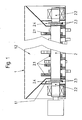
- eine längstgeschnittene Seitenansicht der Zerkleinerungsmaschine,
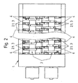
- Fig. 2
- eine
Draufsicht nach Figur 1, - Fig. 3
- den Querschnitt
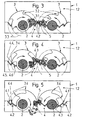
entsprechend den Figuren 1 und 2 in vereinfachter Darstellung der erfindungswesentlichen Merkmale der Phasen des Wirkungsprinzips der Erfindung zwischen den Zerkleinerungswerkzeugen und den starren Schneidwerkzeugen in der Arbeitsphase des aufgegebenen und noch nicht zerkleinerten Materials, - Fig. 4:
- den Querschnitt analog zu
Figur 3 in der Arbeitsphase des begonnenen Zerkleinerungsprozesses und - Fig. 5:
- den Querschnitt analog zu
den Figuren 3 und 4 in der Arbeitsphase der weiteren Zerkleinerung.
- Fig. 1
- a long-cut side view of the crusher,
- Fig. 2
- a plan view of Figure 1,
- Fig. 3
- the cross-section according to Figures 1 and 2 in a simplified representation of the invention essential features of the phases of the principle of action of the invention between the crushing tools and the rigid cutting tools in the working phase of the discontinued and not yet crushed material,
- 4:
- the cross section similar to Figure 3 in the working phase of the crushing process started and
- Fig. 5:
- the cross section analogous to Figures 3 and 4 in the working phase of further crushing.
Eine erfindungsgemäße Zerkleinerungsmaschine für Hausmüll, Sperrmüll oder Holz besteht gemäß den Figuren 1 und 2 aus einem Gehäuse 1 mit zwei darin gelagerten, gegenläufig angetriebenen Wellen 2. Auf den Wellen 2 sind Scheiben 2.1 angeordnet, die Zerkleinerungswerkzeuge 3 aufweisen. Diese Zerkleinerungswerkzeuge sind so mit Abstand zueinander auf den Wellen 2 gereiht, dass sie in Zusammenwirkung mit starren Schneidwerkzeugen 4, die in axialer Richtung der Wellen 2 als Bramme verlaufen, parallelversetzt arbeiten und ein über eine Aufnahme 1.2 aufgegebenes Material 5 schneidend zerkleinern.According to FIGS. 1 and 2, a shredder according to the invention for household waste, bulky waste or wood consists of a
Gegenüber dem bekannten Stand der Technik ist es für die technische Anforderung an die Zerkleinerungsmaschine wesentlich, dass gedachte Verlängerungen der Schneidkanten 4.1 (Figuren 3 bis 5) der starren Schneidwerkzeuge 4 nicht die Achse der Wellen 2 oder Bereiche um die Achse herum schneiden.Compared to the known state of the art, it is essential for the technical requirement of the comminution machine that imaginary extensions of the cutting edges 4.1 (FIGS. 3 to 5) of the
Diese Anforderung zielt darauf ab, dass im Zusammenspiel der Zerkleinerungswerkzeuge 3 mit den starren Schneidwerkzeugen 4 das Material 5 differenziert erfasst, gefördert und fixiert gegen die starren Schneidwerkzeuge 4 mit spezifisch geringen Kräften zerkleinert werden kann. Das heißt, dass der Wirkungsgrad der Zerkleinerungsmaschine hinsichtlich des Zerkleinerungsprozesses im Vergleich zu den herkömmlichen Zerreißem wesentlich gesteigert wird.This requirement is aimed at that, in interaction with the
Entsprechend den Figuren 3 bis 5 weisen die Zerkleinerungswerkzeuge 3 in jeweils eine Drehrichtung der Wellen 2 und in deren Querschnitt gesehen zwei Schneidenbereiche 3.1, 3.2 auf, die so gestaltet sind, dass die Stabilität der Zerkleinerungswerkzeuge 3 nicht gefährdet ist.According to FIGS. 3 to 5, the
Ein innerer Schneidenbereich 3.1 erfasst mehr zu zerkleinerndes Material 5 und wirkt mit einem relativ kleinen Hebelarm sowie ein äußerer Schneidenbereich 3.2 erfasst weniger zu zerkleinerndes Material 5 und wirkt mit einem relativ großen Hebelarm. Dabei beschreiben die Konturen 3.3 besagter Schneidenbereiche 3.1, 3.2 in Richtung der Achsen der Wellen 2 jeweils einen konzentrischen Kreisbogen um die Wellen 2.An inner cutting area 3.1 detects more material to be comminuted 5 and acts with a relatively small lever arm and an outer cutting area 3.2 detects less material to be shredded 5 and acts with a relatively large lever arm. The contours 3.3 of said cutting areas 3.1, 3.2 in the direction of the axes of the
Im Ansatz ist mit dieser konstruktiven Ausführung die Voraussetzung gegeben, die verfügbaren Kräfte wirksamer als bisher für den Zerkleinerungsprozess des jeweiligen Materials und differenzierter einzusetzen.In the beginning, with this structural design, the prerequisite is given to use the available forces more effectively than before for the comminution process of the respective material and differentiated.
In funktioneller Korrespondenz dazu weisen die starren Schneidwerkzeuge 4 mehrere sägeartig angeordnete Zähne 4.2 auf. Somit arbeiten zwei im Winkel zueinander stehende Zahnflanken 4.3 der Zähne 4.2 mit mindestens einem der Schneidenbereiche 3.1, 3.2 derart zusammen, dass das jeweilige Material 5 stets eingeklemmt und von den verfügbaren Kanten der Schneiden allumfassend eingekerbt und geschnitten wird.In functional correspondence thereto, the
Funktionell mit diesem Effekt verschmelzend kommt hinzu, dass in jeder beginnenden, wirksam werdenden Schneidstellung eine, eine jeweils erste Querschneide 3.4 bildende Spitze der Zerkleinerungswerkzeuge 3 gegen eine, eine jeweils zweite Querschneide 4.4 bildende Spitze eines Zahnes 4.2 der starren Schneidwerkzeuge 4 parallelversetzt und vorbeischneidend gerichtet ist. Dadurch erhalten die neben den zwischen den Schneidenbereichen 3.1, 3.2 der Zerkleinerungswerkzeuge 3 und den Schneidkanten 4.1 der starren Schneidwerkzeuge 4 erzeugten bzw. wirkenden Schneidkräfte eine zusätzliche sowie parallel zur Achse der Welle 2 gerichtete Brechkante mit auf das jeweilige Stück Material 5 parallel versetzter Kerbwirkung und spezifisch hoch wirkender Kraft.Functionally merging with this effect is added that in each incipient, becoming effective cutting position one, a respective first cross cutting 3.4 forming tip of the crushing
Diese Merkmalskombination unterwirft das Material 5 somit unter aggressiver Teilnahme der Zähne 4.2 der starren Schneidwerkzeuge 4 einem aktiven und zusätzlichen Zerkleinerungsvorgang.This combination of features thus subjecting the
Schlüssig zu den erhöht gestellten Anforderungen und zur gestellten erfindungsgemäßen Aufgabe wird diese Zerkleinerungsmaschine den in der Zerkleinerungspraxis der eingangs umrissenen Arten von Material 5 besser gerecht, indem
- die
Stabilität der Zerkleinerungswerkzeuge 3 erhöht, - der Zerkleinerungsgrad und die Durchsatzleistung gesteigert,
- der Energieverbrauch gesenkt
- increases the stability of the
comminution tools 3, - the degree of comminution and the throughput increased,
- reduced energy consumption
Aus den Figuren 3 bis 5 sind in drei dargestellten Phasen die verbesserten Wirkungen der erfindungsgemäßen Zerkleinerungsmaschine zu entnehmen:
Entsprechend Figur 3 ist schematisch dargestellt, wie die mit unterschiedlichen Hebelarmen wirkenden Schneidenbereiche 3.1, 3.2das Material 5 in unterschiedlichen Volumina erfassen und aufden starren Schneidwerkzeugen 4 zwischen die Zahnflanken 4.3 so verteilen können, dass die Zerkleinerung optimal vorbereitet ist.Mit der Figur 4 wird deutlich wie in funktioneller Verschmelzung einerseits der Wirkungen der Schneidenbereiche 3.1, 3.2 gegen die Schneidkanten 4.1 das in den Zahnflanken 4.3eingeklemmte Material 5 geschnitten und andererseits den korrespondierenden Wirkungen der ersten Querschneiden 3.4 mit den zweiten Querschneiden 4.4 und dem zusätzlichen Brechkanteneffekt ausgesetzt ist.Schließlich zeigt Figur 5 insbesondere die Phase, in der die äußeren Schneidenbereiche 3.2 mit dem großen Hebelarm und dem weniger erfasstenMaterial 5 gegen die starren Schneidwerkzeuge 4 wirken.
- Corresponding to Figure 3 is shown schematically how the acting with different lever arms cutting areas 3.1, 3.2 detect the
material 5 in different volumes and can distribute on therigid cutting tools 4 between the tooth flanks 4.3 so that the crushing is optimally prepared. - With the figure 4 is clearly as in functional fusion on the one hand, the effects of the cutting edges 3.1, 3.2 against the cutting edges 4.1 cut the trapped in the tooth flanks 4.3
material 5 and on the other hand exposed the corresponding effects of the first transverse cutting 3.4 with the second cross cutting 4.4 and the additional refractive edge effect is. - Finally, FIG. 5 particularly shows the phase in which the outer cutting areas 3.2 with the large lever arm and the less sensed
material 5 act against therigid cutting tools 4.
Unter Beibehaltung des erfindungsgemäßen Wirkprinzips und dieses weiter unterstützend sind gemäß den Figuren 1 und 2 die Zerkleinerungswerkzeuge 3 in axialer Richtung auf den Wellen 2 radial zueinander versetzt angeordnet. Nicht in den Figuren dargestellt ist die Möglichkeit, dass die Zerkleinerungswerkzeuge 3 in einer unterschiedlichen Winkelstellung auf der Welle 2, d. h. axial im Schneidprofil, z. B. konisch verlaufend, angeordnet sind. Dementsprechend sind auch die Zähne 4.2 der axial als Bramme verlaufenden starren Schneidwerkzeuge 4 anzuordnen.While retaining the active principle according to the invention and this further supportive, according to FIGS. 1 and 2, the
Die technologisch günstige Ausführung für die Herstellung, den Betrieb, die Wartung und Reparatur der erfindungsgemäßen Zerkleinerungsmaschine wird mit den in der Figur 1 weiter dargestellten Merkmalen erreicht. Dazu weisen die Wellen 2 Zapfen 2.2 mit einem Lagerbereich an den Enden auf. Die Verbindung zwischen den Zapfen 2.2 und der Welle 2 erfolgt mittels Flansche 2.3.The technologically favorable design for the manufacture, operation, maintenance and repair of the crushing machine according to the invention is achieved with the features further illustrated in Figure 1. For this purpose, the
Für den Betrieb in der Praxis ist es zur Unterstützung einer optimalen Zerkleinerung und Zuverlässigkeit der Zerkleinerungsmaschine wichtig, dass kein Material 5 durch gegeneinander abzudichtende Bauteile dringt. Deshalb ist das Gehäuse 1 gemäß Figur 1 an den Stirnseiten mit einer Doppelwand 1.1 ausgeführt, in der die Zapfen 2.2 oder Enden der Welle 2 eine Dichtscheibe 2.4 aufweisen, die mit der Doppelwand 1.1 ein dichtendes Labyrinth bildet. Technologisch vorteilhaft wird die Dichtscheibe 2.4 durch die Flansche 2.3 gebildet.For operation in the field, it is important to support optimal comminution and reliability of the crusher that no
Zur Schonung der starren Schneidwerkzeuge 4 gegen Verschleiß ist es günstig, wie in den Figuren 3 bis 5 angedeutet, die Schneidenkonturen 4.5 mit Verschleißelementen 4.6 auszurüsten.To protect the
In der Gesamtheit der beanspruchten Merkmale kann eine erfindungsgemäß ausgeführte Zerkleinerungsmaschine die gestiegenen Anforderungen an die Zerkleinerung von Material der beschriebenen Arten optimal erfüllen, wobei dazu auch Mittel vorgesehen sind, mit denen der Gradient eines Parameters der Zerkleinerungsmaschine erfasst und als eine Führungsgröße für die Steuerung der Zerkleinerungsmaschine verwendet wird.In the entirety of the claimed features, a crushing machine according to the invention can optimally meet the increased requirements for the comminution of material of the described types, to which means are provided, which detects the gradient of a parameter of the comminution machine and as a reference variable for the control of the comminution machine is used.
- 1 =1 =
- Gehäusecasing
- 1.1 =1.1 =
- Doppelwanddouble wall
- 1.2 =1.2 =
- Aufnahme für MaterialRecording for material
- 2 =2 =
- Wellewave
- 2.1 =2.1 =
- Scheibedisc
- 2.2 =2.2 =
- Zapfenspigot
- 2.3. =2.3. =
- Flanschflange
- 2.4 =2.4 =
- Dichtscheibesealing washer
- 3 =3 =
- Zerkleinerungswerkzeugchopping tool
- 3.1 =3.1 =
- innerer Schneidenbereich, kleiner Hebelarminner cutting area, small lever arm
- 3.2 =3.2 =
- äußerer Schneidenbereich, großer Hebelarmouter cutting area, large lever arm
- 3.3 =3.3 =
- Konturcontour
- 3.4 =3.4 =
- erste Querschneidefirst chisel edge
- 4 =4 =
- starres Schneidwerkzeugrigid cutting tool
- 4.1 =4.1 =
- Schneidkantecutting edge
- 4.2 =4.2 =
- Zahntooth
- 4.3 =4.3 =
- Zahnflanketooth flank
- 4.4 =4.4 =
- zweite Querschneidesecond transverse cutting edge
- 4.5 =4.5 =
- Schneidenkonturcut contour
- 4.6 =4.6 =
- Verschleißelementwear member
- 5 =5 =
- Materialmaterial
Claims (12)
- A comminution machine materials of all kinds, e.g. garbage, such as domestic waste, bulk waste or wood, particularly organic waste or bulky waste, such as refrigerators, tyres, furniture, carpets, mattresses, tree stumps, demolition wood or similar materials, including- a receptacle for the materials (5) disposed in a housing (1)- at least one shaft (2) that is supported in the housing (1), is rotatable in both directions and on which comminution tools are disposed,- rigid cutting tools (4) attached in the housing, the cutting edges (4.1) of which when extended do not intersect the axis of the shaft (2) or an area surrounding the axis, and against which rigid cutting tools (4) the comminution tools of the shaft (2) reduce the materials (5) introduced, whereinin conjunction with the crushing tools (3) of the shaft (2) the materials (5) are grasped according to type, transported and fixed against the rigid cutting tools (4), and reduced with specifically low forces,
characterised in thata) the comminution tools (3) are furnished with at least two cutting areas (3.1, 3.2) in each direction of rotation of the shaft (2) and viewed in the cross section thereof, and of which at least one inner cutting area (3.1) can grasp and reduce material (5) that is to be reduced to a greater degree, and has a relatively small lever arm for this purpose, and at least one outer cutting area (3.2) can grasp and reduce material (5) that is to be reduced to a lesser degree, and has a relatively large lever arm for this purpose, wherein the contours (3.3) of both cutting areas (3.1, 3.2) form a circular arc about the axis of the shaft (2) in the direction of the axis of the shaft (2),b) the rigid cutting tools (4) are furnished with a plurality of teeth (4.2) arranged in the manner of a saw so that the tooth flanks (4.3.) of two teeth (4.2) set at an angle to one another work together with one of the cutting areas (3.1, 3.2) for a cutting effect,c) at the beginning of each effective cutting position a tip of the comminution tool (3) forming a first cross cutting surface (3.4) is facing offset and parallel towards a tip of the tooth (4.2) on the rigid cutting tool (4) forming a second cross cutting surface (4.4) to produce a shearing cutting action, so that the cutting forces generated in addition to the force between the cutting areas (3.1, 3.2) of the comminution tools (3) and the cutting surfaces (4.1) of the rigid cutting tools (4) create an additional crushing edge that works parallel to the axis of the shaft (2) with a force concentration offset and parallel to the material (5) and specific, very powerful force, andd) the material (5) is subjected to an active, additional comminution process with the aggressive involvement of the teeth (4.2) of the rigid cutting tools (4). - The comminution machine in accordance with claim 1,
characterised in that
the angular settings of the comminution tools (3) on the shaft (2) are axially offset relative to one another. - The comminution machine in accordance with either of claims 1 or 2,
characterised in that
the comminution tools (3) are arranged at different radial distances from the axis of the shaft (2). - The comminution machine in accordance with any of claims 1 to 3,
characterised in that
the cutting surface contours (4.5) of the teeth (4.2) of the rigid cutting tools (4) run parallel and axially offset in the manner of a steel slab and at the beginning of each effective cutting position least one of the first cross cutting surfaces (3.4) is facing towards one of the second cross cutting surfaces (4.4) in each case to create a parallel, offset cutting action. - The comminution machine in accordance with any of claims 1 to 4,
characterised in that
the shaft (2) is furnished with discs (2.1) on which the comminution tools (3) are arranged or conformed, and which have a meshing action in the spaces between the rigid cutting tools (4) extending on the steel slab and have a cutting action against them. - The comminution machine in accordance with any of claims 1 to 5,
characterised in that
the shaft (2) is furnished with studs (2.2), which are detachably connected to the shaft (2). - The comminution machine in accordance with any of claims 1 to 6,
characterised in that
the studs (2.2) form a bearing area. - The comminution machine in accordance with any of claims 1 to 7,
characterised in that
the connection between the studs (2.2) and the shaft (2) is created via flanges (2.3). - The comminution machine in accordance with any of claims 1 to 8,
characterised in that
the housing (1) is constructed on the frontal surfaces as a double wall (1.1), and a seal disc (2.4) attached to the shaft (2) is provided in the cavity therebetween, thus creating a form of serpentine seal. - The comminution machine in accordance with any of claims 1 to 9,
characterised in that
the seal disc (2.4) is formed by the flanges (2.3). - The comminution machine in accordance with any of claims 1 to 10,
characterised in that
cutting contours (4.5) of the rigid cutting tools (4) are reinforced by wear elements (4.6). - The comminution machine in accordance with any of claims 1 to 11,
characterised in that
means are provided for optimising the comminution process, with which the gradient of a parameter of the comminution process or of the comminution machine is recorded and used as a reference variable for control unit of the comminution machine.
Applications Claiming Priority (3)
| Application Number | Priority Date | Filing Date | Title |
|---|---|---|---|
| DE10247281 | 2002-10-10 | ||
| DE10247281A DE10247281B3 (en) | 2002-10-10 | 2002-10-10 | Comminuting machine used for comminuting any material comprises comminuting tools having cutting regions in a direction of rotation of a shaft, and rigid cutting tools |
| PCT/DE2003/003375 WO2004035215A1 (en) | 2002-10-10 | 2003-10-09 | Grinding machine for all kinds of material, e.g. waste or wood |
Publications (2)
| Publication Number | Publication Date |
|---|---|
| EP1575708A1 EP1575708A1 (en) | 2005-09-21 |
| EP1575708B1 true EP1575708B1 (en) | 2007-02-28 |
Family
ID=31197627
Family Applications (1)
| Application Number | Title | Priority Date | Filing Date |
|---|---|---|---|
| EP03775058A Expired - Lifetime EP1575708B1 (en) | 2002-10-10 | 2003-10-09 | Grinding machine for all kinds of material, e.g. waste or wood |
Country Status (12)
| Country | Link |
|---|---|
| US (1) | US7237739B2 (en) |
| EP (1) | EP1575708B1 (en) |
| JP (1) | JP4213120B2 (en) |
| AT (1) | ATE355130T1 (en) |
| AU (1) | AU2003283187A1 (en) |
| CA (1) | CA2501376C (en) |
| DE (2) | DE10247281B3 (en) |
| DK (1) | DK1575708T3 (en) |
| ES (1) | ES2283839T3 (en) |
| GB (1) | GB2410908A (en) |
| NO (1) | NO330393B1 (en) |
| WO (1) | WO2004035215A1 (en) |
Cited By (1)
| Publication number | Priority date | Publication date | Assignee | Title |
|---|---|---|---|---|
| DE102008052490A1 (en) | 2008-10-21 | 2010-04-22 | Metso Lindemann Gmbh | Arrangement for the axial support of a shaft of a working machine |
Families Citing this family (10)
| Publication number | Priority date | Publication date | Assignee | Title |
|---|---|---|---|---|
| DK176582B1 (en) | 2005-06-22 | 2008-10-06 | M & J Ind As | Crushing Machine |
| IS2409B (en) * | 2005-11-11 | 2008-10-15 | Örn Jensson Guðmundur | Equipment for cutting down |
| DE202010005584U1 (en) * | 2010-06-08 | 2011-11-03 | Amni Maschinenbau Gmbh | crusher |
| DE102011001925A1 (en) * | 2011-04-08 | 2012-10-11 | Wincor Nixdorf International Gmbh | Device for compacting containers |
| DE102011119615B4 (en) * | 2011-11-29 | 2014-05-22 | Schenck Process Gmbh | Lump breaker and method for breaking lumps contained in a bulk flow |
| ES2525671T3 (en) * | 2012-06-29 | 2014-12-29 | Borislav VUJADINOVIC | Spray device for spraying a base material, e.g. ex. pellet |
| CN103191811B (en) * | 2013-04-16 | 2016-07-06 | 上海绿环机械有限公司 | A kind of reducing mechanism and the trash compactor with reducing mechanism |
| DE102014108607A1 (en) * | 2014-06-18 | 2015-12-24 | Betek Gmbh & Co. Kg | against cutting |
| DE202017002006U1 (en) | 2017-04-15 | 2017-04-26 | Bernhard Elbers | container compressor |
| DE102018108300B4 (en) | 2017-08-09 | 2024-01-11 | Hermann Schwelling | Bearing arrangement and processing device equipped with it |
Family Cites Families (6)
| Publication number | Priority date | Publication date | Assignee | Title |
|---|---|---|---|---|
| DK169378B1 (en) * | 1990-03-21 | 1994-10-17 | Separation A S Niro | Device for material breakdown |
| FR2703928B1 (en) | 1993-04-16 | 1995-06-23 | Caruelle | APPARATUS FOR FRAGMING SOLID OBJECTS. |
| DK0928222T4 (en) * | 1995-09-12 | 2007-06-11 | M & J Ind As | Crushing Machine |
| EP1072314A1 (en) * | 1999-07-22 | 2001-01-31 | Sté Moditec | Form of the active part of a knife for a knife-crusher |
| JP2002045720A (en) * | 2000-08-02 | 2002-02-12 | Tezuka:Kk | Biaxial crusher |
| US20030230657A1 (en) * | 2002-06-14 | 2003-12-18 | John Dorscht | Primary reduction apparatus |
-
2002
- 2002-10-10 DE DE10247281A patent/DE10247281B3/en not_active Expired - Fee Related
-
2003
- 2003-10-09 DE DE50306699T patent/DE50306699D1/en not_active Expired - Lifetime
- 2003-10-09 ES ES03775058T patent/ES2283839T3/en not_active Expired - Lifetime
- 2003-10-09 CA CA 2501376 patent/CA2501376C/en not_active Expired - Fee Related
- 2003-10-09 US US10/530,923 patent/US7237739B2/en not_active Expired - Fee Related
- 2003-10-09 AU AU2003283187A patent/AU2003283187A1/en not_active Abandoned
- 2003-10-09 JP JP2004543961A patent/JP4213120B2/en not_active Expired - Fee Related
- 2003-10-09 EP EP03775058A patent/EP1575708B1/en not_active Expired - Lifetime
- 2003-10-09 WO PCT/DE2003/003375 patent/WO2004035215A1/en active IP Right Grant
- 2003-10-09 DK DK03775058T patent/DK1575708T3/en active
- 2003-10-09 GB GB0507770A patent/GB2410908A/en not_active Withdrawn
- 2003-10-09 AT AT03775058T patent/ATE355130T1/en active
-
2005
- 2005-04-28 NO NO20052079A patent/NO330393B1/en not_active IP Right Cessation
Cited By (2)
| Publication number | Priority date | Publication date | Assignee | Title |
|---|---|---|---|---|
| DE102008052490A1 (en) | 2008-10-21 | 2010-04-22 | Metso Lindemann Gmbh | Arrangement for the axial support of a shaft of a working machine |
| EP2180200A1 (en) | 2008-10-21 | 2010-04-28 | Metso Lindemann GmbH | Assembly for axial support of a shaft of a work machine |
Also Published As
| Publication number | Publication date |
|---|---|
| JP4213120B2 (en) | 2009-01-21 |
| AU2003283187A1 (en) | 2004-05-04 |
| ATE355130T1 (en) | 2006-03-15 |
| GB2410908A (en) | 2005-08-17 |
| NO330393B1 (en) | 2011-04-04 |
| DE50306699D1 (en) | 2007-04-12 |
| NO20052079L (en) | 2005-04-28 |
| GB0507770D0 (en) | 2005-05-25 |
| US20060065769A1 (en) | 2006-03-30 |
| CA2501376A1 (en) | 2004-04-29 |
| JP2006507920A (en) | 2006-03-09 |
| ES2283839T3 (en) | 2007-11-01 |
| DE10247281B3 (en) | 2004-03-04 |
| EP1575708A1 (en) | 2005-09-21 |
| CA2501376C (en) | 2008-08-05 |
| DK1575708T3 (en) | 2007-06-25 |
| US7237739B2 (en) | 2007-07-03 |
| WO2004035215A1 (en) | 2004-04-29 |
Similar Documents
| Publication | Publication Date | Title |
|---|---|---|
| EP1731223B1 (en) | Comminutor | |
| DE69608918T3 (en) | CRUSHING DEVICE | |
| EP2666542B1 (en) | Crusher with a rapidly exchangeable cutter block | |
| DE3234298C2 (en) | Hammer crusher | |
| EP1575708B1 (en) | Grinding machine for all kinds of material, e.g. waste or wood | |
| DE102009060523A1 (en) | Crushing device with counter knife device | |
| EP0346661A2 (en) | Chopping and shredding machine | |
| DE3221431C2 (en) | ||
| DE2450936A1 (en) | DEVICE FOR DISCUSSING BULK GOODS TO BE DESTRUCTED | |
| EP1497032B1 (en) | Crushing device | |
| DE102015005859B4 (en) | Disc chipper for shredding chunky feed, in particular of wood | |
| EP2374544B1 (en) | Device for grinding compostable material | |
| DE2502665A1 (en) | WASTE SHREDDING DEVICE | |
| EP0124138B1 (en) | Method and apparatus for grinding vegetal products | |
| JPH0783841B2 (en) | Equipment for crushing objects | |
| EP2394743A1 (en) | Grinding machine | |
| DE102019108306A1 (en) | Cutting mill for cutting samples | |
| DE102012204330B3 (en) | Grinding tool for grinding roller of grinding device, has support plate, which is fixed to shaft, where closed-area blade ring is arranged on outer periphery of support plate | |
| DE4342647A1 (en) | Shredding device with electrically-operated blade rotor | |
| AT511382B1 (en) | ROTOR CUTTER | |
| DE10048886C2 (en) | Device for comminuting feed material with a comminuting system rotating about an axis of rotation | |
| DE7818838U1 (en) | MACHINE FOR CRUSHING WASTE MATERIALS | |
| DE4328687A1 (en) | Shredder operating by the rotary-shears principle | |
| DE2827544A1 (en) | Disintegrator for used tyres - has twin counter-rotating shafts which carry cutting discs meeting in pairs with tapered separators | |
| DE4240444C2 (en) | Rotor shears for crushing particularly bulky waste |
Legal Events
| Date | Code | Title | Description |
|---|---|---|---|
| PUAI | Public reference made under article 153(3) epc to a published international application that has entered the european phase |
Free format text: ORIGINAL CODE: 0009012 |
|
| 17P | Request for examination filed |
Effective date: 20050510 |
|
| AK | Designated contracting states |
Kind code of ref document: A1 Designated state(s): AT BE BG CH CY CZ DE DK EE ES FI FR GB GR HU IE IT LI LU MC NL PT RO SE SI SK TR |
|
| AX | Request for extension of the european patent |
Extension state: AL LT LV MK |
|
| GRAP | Despatch of communication of intention to grant a patent |
Free format text: ORIGINAL CODE: EPIDOSNIGR1 |
|
| DAX | Request for extension of the european patent (deleted) | ||
| GRAS | Grant fee paid |
Free format text: ORIGINAL CODE: EPIDOSNIGR3 |
|
| RIN1 | Information on inventor provided before grant (corrected) |
Inventor name: KOCK, BERNHARD |
|
| GRAA | (expected) grant |
Free format text: ORIGINAL CODE: 0009210 |
|
| AK | Designated contracting states |
Kind code of ref document: B1 Designated state(s): AT BE BG CH CY CZ DE DK EE ES FI FR GB GR HU IE IT LI LU MC NL PT RO SE SI SK TR |
|
| PG25 | Lapsed in a contracting state [announced via postgrant information from national office to epo] |
Ref country code: SI Free format text: LAPSE BECAUSE OF FAILURE TO SUBMIT A TRANSLATION OF THE DESCRIPTION OR TO PAY THE FEE WITHIN THE PRESCRIBED TIME-LIMIT Effective date: 20070228 Ref country code: IE Free format text: LAPSE BECAUSE OF FAILURE TO SUBMIT A TRANSLATION OF THE DESCRIPTION OR TO PAY THE FEE WITHIN THE PRESCRIBED TIME-LIMIT Effective date: 20070228 |
|
| REG | Reference to a national code |
Ref country code: GB Ref legal event code: FG4D Free format text: NOT ENGLISH |
|
| REG | Reference to a national code |
Ref country code: CH Ref legal event code: EP |
|
| REF | Corresponds to: |
Ref document number: 50306699 Country of ref document: DE Date of ref document: 20070412 Kind code of ref document: P |
|
| REG | Reference to a national code |
Ref country code: IE Ref legal event code: FG4D Free format text: LANGUAGE OF EP DOCUMENT: GERMAN |
|
| REG | Reference to a national code |
Ref country code: SE Ref legal event code: TRGR |
|
| REG | Reference to a national code |
Ref country code: CH Ref legal event code: NV Representative=s name: HANS RUDOLF GACHNANG PATENTANWALT |
|
| PG25 | Lapsed in a contracting state [announced via postgrant information from national office to epo] |
Ref country code: BG Free format text: LAPSE BECAUSE OF EXPIRATION OF PROTECTION Effective date: 20070529 |
|
| REG | Reference to a national code |
Ref country code: DK Ref legal event code: T3 |
|
| PG25 | Lapsed in a contracting state [announced via postgrant information from national office to epo] |
Ref country code: PT Free format text: LAPSE BECAUSE OF FAILURE TO SUBMIT A TRANSLATION OF THE DESCRIPTION OR TO PAY THE FEE WITHIN THE PRESCRIBED TIME-LIMIT Effective date: 20070730 |
|
| ET | Fr: translation filed | ||
| GBV | Gb: ep patent (uk) treated as always having been void in accordance with gb section 77(7)/1977 [no translation filed] |
Effective date: 20070228 |
|
| REG | Reference to a national code |
Ref country code: IE Ref legal event code: FD4D |
|
| REG | Reference to a national code |
Ref country code: ES Ref legal event code: FG2A Ref document number: 2283839 Country of ref document: ES Kind code of ref document: T3 |
|
| PG25 | Lapsed in a contracting state [announced via postgrant information from national office to epo] |
Ref country code: GB Free format text: LAPSE BECAUSE OF FAILURE TO SUBMIT A TRANSLATION OF THE DESCRIPTION OR TO PAY THE FEE WITHIN THE PRESCRIBED TIME-LIMIT Effective date: 20070228 Ref country code: SK Free format text: LAPSE BECAUSE OF FAILURE TO SUBMIT A TRANSLATION OF THE DESCRIPTION OR TO PAY THE FEE WITHIN THE PRESCRIBED TIME-LIMIT Effective date: 20070228 |
|
| PG25 | Lapsed in a contracting state [announced via postgrant information from national office to epo] |
Ref country code: RO Free format text: LAPSE BECAUSE OF FAILURE TO SUBMIT A TRANSLATION OF THE DESCRIPTION OR TO PAY THE FEE WITHIN THE PRESCRIBED TIME-LIMIT Effective date: 20070228 Ref country code: CZ Free format text: LAPSE BECAUSE OF FAILURE TO SUBMIT A TRANSLATION OF THE DESCRIPTION OR TO PAY THE FEE WITHIN THE PRESCRIBED TIME-LIMIT Effective date: 20070228 |
|
| PLBE | No opposition filed within time limit |
Free format text: ORIGINAL CODE: 0009261 |
|
| STAA | Information on the status of an ep patent application or granted ep patent |
Free format text: STATUS: NO OPPOSITION FILED WITHIN TIME LIMIT |
|
| 26N | No opposition filed |
Effective date: 20071129 |
|
| PG25 | Lapsed in a contracting state [announced via postgrant information from national office to epo] |
Ref country code: GR Free format text: LAPSE BECAUSE OF FAILURE TO SUBMIT A TRANSLATION OF THE DESCRIPTION OR TO PAY THE FEE WITHIN THE PRESCRIBED TIME-LIMIT Effective date: 20070529 |
|
| PG25 | Lapsed in a contracting state [announced via postgrant information from national office to epo] |
Ref country code: MC Free format text: LAPSE BECAUSE OF NON-PAYMENT OF DUE FEES Effective date: 20071031 |
|
| PG25 | Lapsed in a contracting state [announced via postgrant information from national office to epo] |
Ref country code: EE Free format text: LAPSE BECAUSE OF FAILURE TO SUBMIT A TRANSLATION OF THE DESCRIPTION OR TO PAY THE FEE WITHIN THE PRESCRIBED TIME-LIMIT Effective date: 20070228 |
|
| PG25 | Lapsed in a contracting state [announced via postgrant information from national office to epo] |
Ref country code: CY Free format text: LAPSE BECAUSE OF FAILURE TO SUBMIT A TRANSLATION OF THE DESCRIPTION OR TO PAY THE FEE WITHIN THE PRESCRIBED TIME-LIMIT Effective date: 20070228 |
|
| PG25 | Lapsed in a contracting state [announced via postgrant information from national office to epo] |
Ref country code: HU Free format text: LAPSE BECAUSE OF FAILURE TO SUBMIT A TRANSLATION OF THE DESCRIPTION OR TO PAY THE FEE WITHIN THE PRESCRIBED TIME-LIMIT Effective date: 20070901 Ref country code: TR Free format text: LAPSE BECAUSE OF FAILURE TO SUBMIT A TRANSLATION OF THE DESCRIPTION OR TO PAY THE FEE WITHIN THE PRESCRIBED TIME-LIMIT Effective date: 20070228 |
|
| PGFP | Annual fee paid to national office [announced via postgrant information from national office to epo] |
Ref country code: LU Payment date: 20121024 Year of fee payment: 10 |
|
| PGFP | Annual fee paid to national office [announced via postgrant information from national office to epo] |
Ref country code: DK Payment date: 20121025 Year of fee payment: 10 |
|
| PGFP | Annual fee paid to national office [announced via postgrant information from national office to epo] |
Ref country code: FR Payment date: 20121113 Year of fee payment: 10 Ref country code: FI Payment date: 20121022 Year of fee payment: 10 Ref country code: DE Payment date: 20121013 Year of fee payment: 10 Ref country code: CH Payment date: 20121024 Year of fee payment: 10 Ref country code: BE Payment date: 20121022 Year of fee payment: 10 |
|
| PGFP | Annual fee paid to national office [announced via postgrant information from national office to epo] |
Ref country code: SE Payment date: 20121024 Year of fee payment: 10 Ref country code: ES Payment date: 20121023 Year of fee payment: 10 Ref country code: IT Payment date: 20121025 Year of fee payment: 10 |
|
| PGFP | Annual fee paid to national office [announced via postgrant information from national office to epo] |
Ref country code: NL Payment date: 20121018 Year of fee payment: 10 Ref country code: AT Payment date: 20121022 Year of fee payment: 10 |
|
| REG | Reference to a national code |
Ref country code: CH Ref legal event code: NV Representative=s name: GACHNANG AG PATENTANWAELTE, CH |
|
| BERE | Be: lapsed |
Owner name: METSO LINDEMANN G.M.B.H. Effective date: 20131031 |
|
| REG | Reference to a national code |
Ref country code: NL Ref legal event code: V1 Effective date: 20140501 |
|
| REG | Reference to a national code |
Ref country code: DK Ref legal event code: EBP Effective date: 20131031 |
|
| REG | Reference to a national code |
Ref country code: CH Ref legal event code: PL |
|
| REG | Reference to a national code |
Ref country code: SE Ref legal event code: EUG |
|
| REG | Reference to a national code |
Ref country code: AT Ref legal event code: MM01 Ref document number: 355130 Country of ref document: AT Kind code of ref document: T Effective date: 20131009 |
|
| PG25 | Lapsed in a contracting state [announced via postgrant information from national office to epo] |
Ref country code: CH Free format text: LAPSE BECAUSE OF NON-PAYMENT OF DUE FEES Effective date: 20131031 Ref country code: LI Free format text: LAPSE BECAUSE OF NON-PAYMENT OF DUE FEES Effective date: 20131031 |
|
| REG | Reference to a national code |
Ref country code: FR Ref legal event code: ST Effective date: 20140630 |
|
| REG | Reference to a national code |
Ref country code: DE Ref legal event code: R119 Ref document number: 50306699 Country of ref document: DE Effective date: 20140501 |
|
| PG25 | Lapsed in a contracting state [announced via postgrant information from national office to epo] |
Ref country code: SE Free format text: LAPSE BECAUSE OF NON-PAYMENT OF DUE FEES Effective date: 20131010 Ref country code: FI Free format text: LAPSE BECAUSE OF NON-PAYMENT OF DUE FEES Effective date: 20131009 Ref country code: DE Free format text: LAPSE BECAUSE OF NON-PAYMENT OF DUE FEES Effective date: 20140501 Ref country code: FR Free format text: LAPSE BECAUSE OF NON-PAYMENT OF DUE FEES Effective date: 20131031 Ref country code: NL Free format text: LAPSE BECAUSE OF NON-PAYMENT OF DUE FEES Effective date: 20140501 Ref country code: AT Free format text: LAPSE BECAUSE OF NON-PAYMENT OF DUE FEES Effective date: 20131009 Ref country code: IT Free format text: LAPSE BECAUSE OF NON-PAYMENT OF DUE FEES Effective date: 20131009 |
|
| PG25 | Lapsed in a contracting state [announced via postgrant information from national office to epo] |
Ref country code: BE Free format text: LAPSE BECAUSE OF NON-PAYMENT OF DUE FEES Effective date: 20131031 |
|
| PG25 | Lapsed in a contracting state [announced via postgrant information from national office to epo] |
Ref country code: DK Free format text: LAPSE BECAUSE OF NON-PAYMENT OF DUE FEES Effective date: 20131031 |
|
| REG | Reference to a national code |
Ref country code: ES Ref legal event code: FD2A Effective date: 20150709 |
|
| PG25 | Lapsed in a contracting state [announced via postgrant information from national office to epo] |
Ref country code: LU Free format text: LAPSE BECAUSE OF NON-PAYMENT OF DUE FEES Effective date: 20131009 Ref country code: ES Free format text: LAPSE BECAUSE OF NON-PAYMENT OF DUE FEES Effective date: 20131010 |