EP1574430B1 - Vorrichtung und Verfahren zur Vermeidung einer Maximallenkwinkelüberschreitung - Google Patents
Vorrichtung und Verfahren zur Vermeidung einer Maximallenkwinkelüberschreitung Download PDFInfo
- Publication number
- EP1574430B1 EP1574430B1 EP05251360A EP05251360A EP1574430B1 EP 1574430 B1 EP1574430 B1 EP 1574430B1 EP 05251360 A EP05251360 A EP 05251360A EP 05251360 A EP05251360 A EP 05251360A EP 1574430 B1 EP1574430 B1 EP 1574430B1
- Authority
- EP
- European Patent Office
- Prior art keywords
- aircraft
- tractor
- sensor
- signal
- uncollimated
- Prior art date
- Legal status (The legal status is an assumption and is not a legal conclusion. Google has not performed a legal analysis and makes no representation as to the accuracy of the status listed.)
- Not-in-force
Links
Images


Classifications
-
- B—PERFORMING OPERATIONS; TRANSPORTING
- B64—AIRCRAFT; AVIATION; COSMONAUTICS
- B64F—GROUND OR AIRCRAFT-CARRIER-DECK INSTALLATIONS SPECIALLY ADAPTED FOR USE IN CONNECTION WITH AIRCRAFT; DESIGNING, MANUFACTURING, ASSEMBLING, CLEANING, MAINTAINING OR REPAIRING AIRCRAFT, NOT OTHERWISE PROVIDED FOR; HANDLING, TRANSPORTING, TESTING OR INSPECTING AIRCRAFT COMPONENTS, NOT OTHERWISE PROVIDED FOR
- B64F1/00—Ground or aircraft-carrier-deck installations
- B64F1/22—Ground or aircraft-carrier-deck installations for handling aircraft
- B64F1/223—Ground or aircraft-carrier-deck installations for handling aircraft for towing aircraft
- B64F1/225—Vehicles specially adapted therefor, e.g. aircraft tow tractors
- B64F1/227—Vehicles specially adapted therefor, e.g. aircraft tow tractors for direct connection to aircraft, e.g. tow tractors without towing bars
Definitions
- the present invention relates generally to an aircraft tractor and, more particularly to a turn-out sensor for such a tractor.
- a tractor attaches to the aircraft's landing gear and provides the propulsion power to move the aircraft.
- the aircraft steering angle is the angle between the wheel of the nose landing gear and the longitudinal axis of the aircraft. Regardless of the direction of the deviation, the steering angle is usually referred to in an absolute sense (e.g., 70°) rather than as signed values (e.g., -55°). Because it is possible, with either type of tractor, to steer the nose landing gear beyond its mechanical limits (known as "over-steer"), an indicator of such a condition would be useful. If a maximum aircraft steering angle is being exceeded, then damage to the aircraft and tractor is possible.
- Past attempts at alerting tractor operators to over-steer conditions have focused on detecting when a maximum steering angle has be reached. At such a point, damage may already be occurring to either the tractor or the aircraft or it may be too late for the operator to react and correct the situation. Still other attempts at addressing this problem have included an over-torque sensor on the tractor that mechanically detects that the maximum over-steer condition has been met. Typically, the over-torque sensor can control the drive motor of the tractor so as to disengage it if needed or trip an alarm that alerts an operator. Other attempts have included, for example, measuring multiple distances from the tractor and the two sides of the aircraft in order to calculate the steering angle.
- a source of collimated radiation directs a beam onto a surface of the aircraft having at least two significantly different reflecting areas (e.g. a light material arc bounded by dark material marks). Reflection of the collimated beam, or lack thereof, is detected and used to determines whether the steering angle is within an acceptable range.
- US-A-4,745,410 Schouller et al discloses a towing vehicle monitoring device for calculating the turn-out angle between the longitudinal axes of the towing vehicle and the aircraft by measuring the relative distance between two opposing transmitters/receivers for sound or other pulse signals and the fuselage of the aircraft. An algorithm is required to calculate the turn-out angle based on the difference between the two measured distances and the known curvature of the specific aircraft type nose.
- embodiments of the present invention provide an early warning to a tractor operator engaged in towing or pushing an aircraft.
- two detectors are used to create a detection area in which the aircraft should be present when the steering angle is well within a safe range.
- one of the detectors fails to detect the presence of the aircraft, then the operator is alerted, before over steering can occur, in order that corrective action can be undertaken.
- these detectors minimize false positives, are simple to operate, and perform reliably in a wide range of weather conditions and lighting environments.
- these embodiments do not require performing complex algorithms, using collimated energy sources, nor modifying the fuselage of an aircraft. In other embodiments, only one detector is used.
- One aspect of the present invention relates to an over-steer avoidance system for an aircraft tractor that utilizes two uncollimated energy transmitters and receivers, such as ultrasonic detectors.
- the ultrasonic detectors are positioned on the tractor such that when the tractor is engaged with the aircraft, one ultrasonic detector is located on each side of the aircraft's fuselage.
- Each ultrasonic sensor includes a coverage area in which a target within that area will result in a reflection signal being returned to the sensor.
- the sensors are positioned such that both sensors will detect the presence of the aircraft within their respective coverage areas when the aircraft steering angle is within a safe range. However, when a predetermined steering angle is exceeded, one of the sensors will not receive a reflected signal and, therefore, will activate an alarm.
- This predetermined angle can be less than the maximum possible over-steer angle, so that the operator is warned of the potential condition early enough to easily take corrective action.
- the operator can reduce the steering angle so as to avoid over-steer or, alternatively, more closely monitor the towing activity with the awareness that over-steering may occur.
- Other embodiments of the present invention contemplate utilizing a single sensor that is able to detect the presence of a region near the nose of the aircraft when the steering angle is within a permitted range but detects its absence when the over steering angle exceeds a threshold angle.
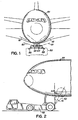
- Fig. 1 illustrates a front view of a tow tractor and aircraft showing the cone-shaped sensing area of a pair of ultrasonic sensors.
- Fig. 2 illustrates a perspective view of an arrangement as in Fig. 1.
- Fig. 3 illustrates a perspective view of a tow tractor and aircraft when the steering angle has caused the aircraft to leave the sensing area of one of the ultrasonic sensors.
- Fig. 4 illustrates a schematic view of pertinent circuitry within a tow tractor that includes an early warning over steering system in accordance with embodiments of the present invention.
- Fig. 5 illustrates a flowchart of an exemplary method of warning of over steering condition in accordance with an embodiment of the present invention.
- FIG. 6 illustrates an alternative embodiment in which a single sensor is used to provide warning of an over steering condition.
- ultrasonic sensors are well understood by a skilled artisan in this field. However, as a brief background, such a sensor emits ultrasonic waves in a cone-shaped pattern. When the ultrasonic waves encounter a reflective target, some energy is reflected to the sensor and subsequently detected. Ultrasonic sensors, in particular, receive reflected energy over a wide range of incidence angles between the sensor and the target. An ultrasonic sensor typically has a detection window such that targets less than a minimum distance away are not detected and returns from targets farther than a maximum distance are ignored. Some parameters that characterize an ultrasonic sensor include its range, its operating frequency, and its beam angle. In response to the detection of a target within the sensing area, the sensor will output a signal, typically an electrical pulse that is received, and processed, by other circuitry that responds appropriately to the pulse.
- a signal typically an electrical pulse that is received, and processed, by other circuitry that responds appropriately to the pulse.
- Fig. 1 illustrates a front view of a towbarless tractor 102 engaged with an aircraft 104 in a straight-ahead towing position.
- the towbarless tractor 102 is depicted transparently, so as not to obscure the location and view of the ultrasonic sensors 106, 108. These sensors are located substantially near the rear of the tractor 102 and on each side of the tractor 102. Looking from the front of the tractor 102 (and the aircraft 104), the ultrasonic sensor 106 is on the left side of the tractor 102 and the other sensor 108 is on the right side of the tractor 102.
- the sensors 106, 108 are located nearly at the edge of their respective sides of the tractor 102. Additionally, the sensors 106, 108 are located to the rear of the tractor 102 so that they are behind the front landing gear of the aircraft 104 when the tractor 102 has engaged the aircraft.
- Each ultrasonic sensor emits a conical, or substantially conical, area of ultrasonic waves.
- the cone 101 from the sensor 106 has a major axis 110 and the cone 103 from the sensor 108 has a major axis 112.
- the angle 120, 122 each major axis 110, 112 forms with a horizontal plane are selected so that the aircraft 104 intersects both cones 101, 103 of ultrasonic waves when the aircraft 104 is turned-out less than its over-steer angle. From the perspective view of Fig. 2, the major axes 110, 112 also form an angle 128 with a vertical plane, as well.
- each sensor 106, 108 is located the same distance from the front of the tractor 102; each sensor 106, 108 is located the same distance from the center of the tractor 104; the angle 120 and 122 are the same; and each cone 101, 103 forms the same angle 128.
- These angles 120, 122, and 128 are selected so that the aircraft 104 intersects both cones 101, 103 when the tractor 102 and aircraft 104 form a steering angle between 0 degrees and a predetermined maximum angle, such as one that is less than an over-steer angle.
- the angles 120, 122 and 128 depend on a number of factors such as, for example, the range of sensors 106, 108; the height of the aircraft fuselage 104 above the tractor 102; the beam angle of the sensors 106, 108; and the selected range of steering angles within which the aircraft 104 should intersect the cones 101, 103.
- the maximum steering angle or over-steer condition, varies for different type of aircraft but typically ranges from between approximately 55° - 90° for most commercial passenger jets. Because the tractor 102 can be utilized with a variety of different aircraft, the sensors 106, 108 should be selected and positioned for responding to a wide range of conditions. For example, 45° can be selected as the maximum steering angle in which the aircraft 104 will intersect both cones 101, 103. If that angle is exceeded, the aircraft will not be detected by one of the sensors 106, 108.
- the aircraft 104 is about 0.25-4 meters above the tractor 102, the sensors 106, 108 and their orientation can be identified. While many ultrasonic sensors are manufactured that have a range of around 0.25-4 meters and a beam angle between 5-20 °, one exemplary ultrasonic sensor useful in this application is manufactured by Pepprl+Fuchs® as model UB4000-30GM- E4-V15. This model has a beam angle of around 10° and operates at a frequency of approximately 85kHz With these operational attributes, the angles 120, 122 are selected to be substantially 27.5° and the angle 128 is substantially 15°. These specific values are given by way of example only.
- the sensors 106, 108 do not necessarily have to be arranged symmetrically as depicted in these figures. Various arrangements can be designed as long as their detection areas are aligned to provide the appropriate over-steer warning.
- Fig. 3 illustrates when the aircraft is being steered at an angle that causes it to exit the sensing cone 101. As viewed in Fig. 3 from the front of the tractor 102, a significant portion of the fuselage of the aircraft 104 is to the left of the tractor 102; a condition for which corrective action may be warranted.
- the sensor 106 When the sensor 106 determines that the aircraft 104 is no longer detected within its sensing area 101, the sensor 106 can activate an alarm signal to alert the operator. In response the operator can reduce the steering angle to a safe range, or more carefully monitor the situation with the awareness that the over-steer angle is imminently approaching.
- Fig. 4 illustrates a schematic view of relevant portions of the tractor 102.
- the tractor 102 is a complex system of circuits and assemblies that allow an operator to easily move large aircraft.
- this conventional functionality is well understood by one of ordinary skill, those details are omitted from Fig. 4 so as not to obscure the principles of the present invention.
- the tractor 102 includes a control system 402 that is typically a microprocessor-based, or micro controller-based, control system.
- This system 402 monitors operation of the various parts of the tractor and provides an interface for the operator by which the tractor 102 can be controlled.
- ultrasonic sensors 106, 108 are physically located on the tractor 102.
- the sensors 106, 108 also communicate with the control system 402 over channels 406, 408. These channels can be wireless, or wired; additionally, they can be redundant or have other safety features to identify if communications are lost or other errors or signal degradation exist in the circuitry.
- the sensors 106, 108 are connected with the tractor control systems 402 so that they can be selectively operated during towing operations of the tractor 102. As such, the sensors can be disabled when the tractor 102 is not pushing or towing an aircraft. Additionally, when activated, the sensors 106, 108 communicate to the control system 402 whether the presence of the aircraft 104 is being detected within their respective sensing areas 101, 103. As would be appreciated by a skilled artisan, interrupt-driven as well as polling-based interface methods can be used when the sensors 106, 108 communicate with the control system 402.
- the control system 402 determines that one of the sensors 106, 108 does not detect the aircraft 102, then the control system 402 can activate an alarm 404.
- the alarm will typically be located within the cab of the tractor 102 but can be placed in any location where it is noticeable by the operator, Furthermore, the alarm 404, can be audible, visual, or both and can vary in tone or frequency based on whether the steering condition persists or worsens. It is anticipated that once becoming aware of the alarm 404, the operator will steer the aircraft 104 such that both sensors 106, 108 once again detect the aircraft 102. Once this happens, the control system 402 can deactivate the alarm 404.
- this figure depicts a flowchart of one exemplary algorithm that the tractor control system 402 can implement to avoid over-steer conditions.
- the over-steer avoidance system is activated in step 502.
- the sensors 106, 108 are active and emit sensing cones 101, 103, respectively.
- step 504 one of the sensors 106, 108 determines whether or not it detects the presence of the aircraft 104 in its sensing area.
- step 506 the other of the sensors 106, 108 similarly determines if it detects the presence of the aircraft 104 in its sensing area.
- Both of these monitoring determinations are then used, in step 508, to determine if one of the sensors 106, 108 failed to detect the presence of the aircraft 104. If both sensors 106, 108 detected the aircraft 104, then the alarm can be de-activated (or remain un-activated), in step 512, and monitoring can continue with steps 504 and 506. However, if one of the sensors 106, 108 failed to detect the aircraft 104, then the alarm is activated (or continues to be activated), in step 510, and monitoring continues with step 504 and 506. In response to the state of the alarm 404, the operator can adjust the towing (or pushing) operation of the aircraft 104.
- the ultrasonic sensor arrangement described herein can be retro-fitted to an existing tractor in addition to being originally installed equipment.
- detectors and sensors other than ultrasonic sensors can be utilized as well.
- These other types of sensors can include uncollimated light transmitters and receivers as well as sound-wave transmitters and receivers operating at lower frequencies.
- FIG. 6 illustrates one alternative embodiment in which a single ultrasonic, or other uncollimated energy, sensor is used to provide a warning of an over steering condition.
- each sensor focuses energy on a respective section of the fuselage that moves in relation to the tractor 102 based on the steering angle.
- This area of the fuselage is selected so that it is within a sensor's detection region when the over steering angle is below a threshold and is outside of the sensor's detection region when the over steering angle exceeds a threshold.
- a similar area of the fuselage may be selected and used in conjunction with a single sensor as well. While the specific placement of the single sensor depends on a number of factors, such as, for example, the height of the fuselage and the beam angle of the sensor, the sensor is placed so that it detects a region of the fuselage whose movement is indicative of the steering angle.
- a sensor 604 is placed on a platform 602 of the tractor 102.
- the sensor 604 is placed along the centerline of the tractor 102 so that it aligns with the nose landing gear 608 of the aircraft 104.
- the sensor 604 is located a particular distance 606 in front of the nose landing gear 608.
- the platform 602 advantageously allows the sensor to be moved in a horizontal plane. As the tractor 102 ages while in use, the alignment of the tires and other components may change so that the sensor 604 is no longer aligned with the landing gear 608 and at the desired distance 606. Accordingly, the platform 602 permits adjustment of the location of the sensor 604 using any of a variety of methods known to one of ordinary skill in the art.
- the platform 602 being adjustable in the vertical plane as well so as to effect a change in the height of the sensor 604. Also, to accommodate aircraft of different sizes, the platform 602 may allow an operator of the tractor to adjust the position of the sensor 604 in order to selectively change the distance 606 of the sensor 604 from the nose landing gear 608.
- the senor 604 is an ultrasonic sensor having a beam angle of approximately 40° to 55° and located ahead of the nose landing gear 608 by a distance 606 of approximately six to eight feet. With such a placement of the sensor 604, it will be located about 12 to 18 feet below the nose region of a typical commercial- sized jet aircraft, The sensor 604 is advantageously oriented so that its cone of energy 610 is directed substantially straight-upwards in the vertical direction.
- a maximum steering angle e.g. 45°, or 50°
- some portion 612 of the fuselage is located above the sensor 604 within its detection region.
- the maximum steering angle is exceeded, the entire portion 612 of the fuselage moves so that it no longer "covers" the sensor 604 and thus, the sensor 604 no longer detects the aircraft 104.
- the operator of the tractor 102 is warned of the possible over steering condition.
- the present invention contemplates within its scope using a single sensor arrangement to provide over steering warnings for a number of different aircrafts.
- the fuselage size, shape and height as well as the particular over steering angle for that aircraft would be considered when selecting the sensor's beam angle and location on the tractor. These considerations would be used to determine the sensor's location so that it will detect a region of the aircraft's nose when the steering angle is within a permitted range and not detect that region when a maximum steering angle is exceeded.
- the senor 604 and the two sensors 106 and 108 may be utilized in conjunction with one another to provide a total of three different sensors that may trigger the over steering alarm condition.
- embodiments of the present invention contemplate using one, two, and even more than two sensors to detect the presence or absence of the fuselage from appropriate detections regions so as to provide an alarm indicative of an over-steering condition.
Landscapes
- Engineering & Computer Science (AREA)
- Mechanical Engineering (AREA)
- Aviation & Aerospace Engineering (AREA)
- Measurement Of Velocity Or Position Using Acoustic Or Ultrasonic Waves (AREA)
- Steering Control In Accordance With Driving Conditions (AREA)
- Power Steering Mechanism (AREA)
- Guiding Agricultural Machines (AREA)
Claims (24)
- Verfahren zum Vermeiden einer Lenkwinkelüberschreitung eines Flugzeugs beim Bewegen eines Flugzeugs (104) mit einem Traktor (102), mit den Schritten:Aussenden eines ersten unkollimierten Signals, das einen ersten Winkelabdeckungsbereich (101) von einer ersten Seite des Traktors zu einer ersten Seite des Flugzeugrumpfs bildet;Aussenden eines zweiten unkollimierten Signals, das einen zweiten Winkelabdeckungsbereich (103) von einer zweiten Seite des Traktors zu einer zweiten Seite des Flugzeugrumpfes bildet, wobei sich die ersten und zweiten Abdekkungsbereiche unter dem Flugzeugrumpf überkreuzen;Detektieren einer ersten Reflexion, wenn vorhanden, des ersten Signals;Detektieren einer zweiten Reflexion, wenn vorhanden, des zweiten Signals; undAnzeigen einer Lenkwinkelüberschreitungsbedingung, wenn eine von der ersten Reflexion oder der zweiten Reflexion nicht vorhanden ist.
- Verfahren nach Anspruch 1, wobei die ersten und zweiten unkollimierten Signale Ultraschallsignale sind.
- Verfahren nach einem der vorhergehenden Ansprüche, wobei:Die Lenkwinkelüberschreitungsbedingung die Annäherung an einen Maximallenkwinkel umfasst.
- Verfahren nach Anspruch 1, wobei:Der Schritt des Aussendens des ersten unkollimierten Signals das Aussenden eines ersten Ultraschallsignals umfasst; undder Schritt des Aussendens des zweiten unkollimierten Signals das Aussenden eines zweiten Ultraschallsignals umfasst.
- Verfahren nach einem der vorhergehenden Ansprüche, wobei das Bewegen des Flugzeugs (104) eines von Ziehen und Schieben umfasst.
- Verfahren nach einem der vorhergehenden Ansprüche, wobei der Flugzeugtraktor (102) einen von einem Zugstangentraktor und einem zugstangenlosen Traktor aufweist.
- Verfahren nach einem der vorhergehenden Ansprüche, wobei die Annäherung an die Lenkwinkelüberschreitungsbedingung anzeigt, dasss ein Steuerwinkel des Flugzeugs zwischen etwa 40° und etwa 60° liegt und vorzugsweise 45° ist.
- Verfahren nach einem der vorhergehenden Ansprüche, bei dem:Ein erster Sensor (106) zum Aussenden des ersten unkollimierten Signals und zum Detektieren der ersten Reflexion, wenn vorhanden, an einem Traktor (102) so positioniert wird, dass der erste Abdeckungsbereich (101) sich mit einer ersten Seite des Flugzeugs (104) überschneidet, wenn der Lenkwinkel kleiner als ein Schwellenwert ist;ein zweiter Sensor (108) zum Aussenden des zweiten unkollimierten Signals und zum Detektieren der zweiten Reflexion, wenn vorhanden, an dem Traktor (102) so positioniert wird, dass sich der zweite Abdeckungsbereich (103) mit einer zweiten Seite des Flugzeugs (104) überschneidet, wenn der Lenkwinkel kleiner als der Schwellenwert ist;der erste und zweite Sensor (106, 108) mit einem Steuersystem (402) des, Traktors (102) verbunden werden, wobei das Steuersystem (402) dazu angepasst ist, um festzustellen, ob einer der Sensoren (106, 108) das Nichtvorhandensein des Flugzeugs (104) in ihrem jeweiligen Abdeckungsbereich (101, 103) anzeigt; undein Alarmgeber (404) mit dem Steuersystem (402) operativ verbunden wird, der aktiviert wird, wenn irgendeiner der Sensoren (106, 108) das Nichtvorhandensein des Flugzeugs (104) in dem jeweiligen Abdeckungsbereich (101, 103) anzeigt.
- Verfahren nach Anspruch 8, wobei die Sensoren (106, 108) Ultraschallsensoren sind.
- Verfahren nach Anspruch 8 oder 9, wobei der Schwellenwert kleiner als ein Maximallenkwinkel des Flugzeugs (104) ist.
- Verfahren nach einem der Ansprüche 8 bis 10, wobei der Schwellenwert im Wesentlichen 45° ist.
- Flugzeugtraktor (102), der dazu ausgestaltet ist, um ein Flugzeug (104) durch Eingriff mit einem Bugfahrwerk (608) des Flugzeugs 104 zu bewegen, wodurch ein Lenkwinkel erzeugt wird, der zwischen dem Bugfahrwerk (608) und der Längsachse des Flugzeugs definiert ist, wobei der Traktor (102) aufweist:Einen ersten Sensor (106, 604), der dazu aufgebaut ist, eine erste unkollimierte Signalwelle auszusenden, die einen ersten kegelförmigen Abdeckungsbereich (101, 610) bildet, einen Bereich eines Flugzeugs (104) zu detektieren, wenn der Lenkwinkel kleiner als ein vorgegebener Wert ist, und ein dieses anzeigendes Signal (406) zu liefern;ein Steuersystem (402), das dazu aufgebaut ist, das Signal (406) zu empfangen; undeinen Alarmgeber (404), der mit dem Steuersystem (402) gekoppelt ist und dazu ausgestaltet ist, aktiv zu werden, falls das Signal (406) nicht das Vorhandensein des Bereichs des Flugzeugs anzeigt.
- Traktor (102) nach Anspruch 12, wobei der erste Sensor einen Ultraschallsensor aufweist.
- Traktor nach Anspruch 13, wobei der Ultraschallsensor einen Strahlwinkel von mehr als etwa 50° aufweist.
- Traktor (102) nach Anspruch 12, wobei der erste Sensor (604) so an dem Traktor positioniert ist, dass er im Wesentlichen zwischen 6 und 8 Fuß (1,83 und 2,44 m) entfernt von einer vertikalen Achse des Bugfahrwerks (608) des Flugzeugs (104) liegt, und wobei der erste Sensor (604), wenn der Traktor an dem Bugfahrwerk des Flugzeugs angreift, vorzugsweise entlang der Mittellinie des Traktors (102) angeordnet ist.
- Traktor (102) nach Anspruch 12, der weiter aufweist:Einen zweiten Sensor (108), der dazu aufgebaut ist, um eine zweite unkollimierte Signalwelle auszusenden, die einen zweiten kegelförmigen Abdeckungsbereich (103) bildet, einen zweiten Bereich des Flugzeugs (104) zu detektieren, wenn der Lenkwinkel kleiner als der vorgegebene Wert ist, und ein dieses anzeigendes zweites Signal (408) zu liefern, wobei sich die ersten und zweiten kegelförmigen Abdeckungsbereiche (101, 103) unter dem Flugzeug (104) überkreuzen;ein Steuersystem (102), das dazu aufgebaut ist, die ersten und zweiten Signale (406, 408) von dem ersten und zweiten Sensor (106, 108), die die Detektion des jeweiligen ersten und zweiten Bereichs des Flugzeugs (104) anzeigen, zu empfangen; undeinen Alarmgeber (404), der mit dem Steuersystem (402) verbunden ist und der dazu aufgebaut ist, aktiv zu werden, wenn nicht sowohl das erste und das zweite Signal (406, 408) anzeigen, das die ersten und zweiten Sensoren (106, 108) das Vorhandensein der ersten und zweiten Bereiche des Flugzeugs (104) detektieren.
- Traktor nach Anspruch 16, wobei die ersten und zweiten Sensoren (106, 108) Ultraschallsensoren sind.
- Traktor nach Anspruch 16, wobei die ersten und zweiten Sensoren (106, 108) ein erster Sender und Empfänger von unkollimierter Energie und ein zweiter Sender und Empfänger von unkollimierter Energie sind.
- Traktor (102) nach Anspruch 18, wobei:Der erste Sender und Empfänger für unkollimierte Energie einen ersten Ultraschallsensor aufweist; undder zweite Sender und Empfänger für unkollimierte Energie einen zweiten Ultraschallsensor aufweist.
- Traktor (102) nach einem der Ansprüche 16 bis 19, wobei der vorgegebene Wert kleiner als ein Maximallenkwinkel des Flugzeugs ist und vorzugsweise 45° ist.
- Traktor (102) nach einem der Ansprüche 16 bis 20, wobei der Traktor (102) ein Zugstangentraktor oder ein zugstangenloser Traktor ist.
- Traktor (102) nach einem der Ansprüche 16 bis 21, wobei die ersten und zweiten Sensoren (106, 108) hinter einem Bugfahrwerk (608) des Flugzeugs (104) positionierbar sind, wenn der Traktor (102) in Eingriff mit dem Flugzeug (104) ist.
- Traktor (102) nach einem der Ansprüche 16 bis 22, wobei:Der erste Abdeckungsbereich (101) eine Hauptachse (110) beinhaltet, die gegenüber der Vertikalen zum hinteren Ende des Flugzeugs (104) um etwa 15° abgewinkelt ist, undder zweite Abdeckungsbereich (103) eine Hauptachse (112) beinhaltet, die gegenüber der Vertikalen zum hinteren Ende des Flugzeuges um etwa 15° abgewinkelt ist.
- Traktor (102) nach einem der Ansprüch 16 bis 23 wobei:Der erste Abdeckungsbereich (101) eine Hauptachse (110) beinhaltet, die, gegenüber der Horizontalen, um einen Winkel von etwa 27° nach oben abgewinkelt ist; undder zweite Abdeckungsbereich (103) eine Hauptachse (112) beinhaltet, die gegenüber der Horizontalen um etwa 27° nach oben abgewinkelt ist.
Applications Claiming Priority (2)
| Application Number | Priority Date | Filing Date | Title |
|---|---|---|---|
| US795539 | 2001-02-28 | ||
| US10/795,539 US20050196256A1 (en) | 2004-03-08 | 2004-03-08 | Method and system for over-steer avoidance |
Publications (2)
| Publication Number | Publication Date |
|---|---|
| EP1574430A1 EP1574430A1 (de) | 2005-09-14 |
| EP1574430B1 true EP1574430B1 (de) | 2007-10-03 |
Family
ID=34827584
Family Applications (1)
| Application Number | Title | Priority Date | Filing Date |
|---|---|---|---|
| EP05251360A Not-in-force EP1574430B1 (de) | 2004-03-08 | 2005-03-08 | Vorrichtung und Verfahren zur Vermeidung einer Maximallenkwinkelüberschreitung |
Country Status (4)
| Country | Link |
|---|---|
| US (1) | US20050196256A1 (de) |
| EP (1) | EP1574430B1 (de) |
| AT (1) | ATE374718T1 (de) |
| DE (1) | DE602005002664T2 (de) |
Cited By (3)
| Publication number | Priority date | Publication date | Assignee | Title |
|---|---|---|---|---|
| US8515594B2 (en) | 2008-11-25 | 2013-08-20 | Israel Aerospace Industries Ltd. | Towbarless airplane tug |
| US8935049B2 (en) | 2010-02-16 | 2015-01-13 | Israel Aerospace Industries Ltd. | Plane tractor |
| US9090358B2 (en) | 2006-09-28 | 2015-07-28 | Israel Aerospace Industries Ltd. | System and method for transferring airplanes |
Families Citing this family (29)
| Publication number | Priority date | Publication date | Assignee | Title |
|---|---|---|---|---|
| US7694231B2 (en) * | 2006-01-05 | 2010-04-06 | Apple Inc. | Keyboards for portable electronic devices |
| GB0606087D0 (en) * | 2006-03-27 | 2006-05-03 | Airbus Uk Ltd | Aircraft steering angle warning system |
| US8544792B2 (en) * | 2006-09-28 | 2013-10-01 | Israel Aerospace Industries Ltd. | Towbarless airplane tug |
| US7975959B2 (en) * | 2006-09-28 | 2011-07-12 | Israel Aerospace Industries Ltd. | System and method for transferring airplanes |
| US8245980B2 (en) * | 2006-09-28 | 2012-08-21 | Israel Aerospace Industries Ltd. | System and method for transferring airplanes |
| SG174844A1 (en) | 2006-09-28 | 2011-10-28 | Israel Aerospace Ind Ltd | System and method for transferring airplanes |
| US9199745B2 (en) * | 2007-05-16 | 2015-12-01 | Israel Aerospace Industries Ltd. | System and method for transferring airplanes |
| FR2923461B1 (fr) * | 2007-11-13 | 2010-04-02 | Airbus France | Procede et systeme de desactivation d'un systeme d'orientation d'un train d'atterrisage avant d'un aeronef |
| US8016303B1 (en) * | 2008-06-10 | 2011-09-13 | The United States Of America As Represented By The Secretary Of The Navy | Wheeled-vehicle dolly |
| DE102008035342B4 (de) * | 2008-07-29 | 2011-06-22 | Becker, Andreas, Dipl.-Ing., 42897 | Automatisches System zum Manövrieren von Luftfahrzeugen am Boden |
| IL206061A0 (en) | 2010-05-30 | 2010-11-30 | Israel Aerospace Ind Ltd | Controller for a hydraulic drive system |
| IL206262A0 (en) | 2010-06-09 | 2011-02-28 | Raphael E Levy | System and method for transferring airplanes |
| WO2012145124A2 (en) | 2011-04-22 | 2012-10-26 | Lektro, Inc. | Tow for aircraft |
| WO2013042114A1 (en) | 2011-09-21 | 2013-03-28 | Israel Aerospace Industries Ltd. | System and method for transferring airplanes |
| CN102381483A (zh) * | 2011-09-24 | 2012-03-21 | 威海广泰空港设备股份有限公司 | 飞机牵引车过度转向监测装置 |
| CN103134698A (zh) * | 2012-12-11 | 2013-06-05 | 沈阳北方交通重工有限公司 | 一种带有测试飞机前起落架保护功能的检测装置 |
| US8902084B2 (en) * | 2013-01-31 | 2014-12-02 | Messier-Dowty Inc. | Switch assembly and over-steer detection system |
| IL230099A (en) | 2013-12-23 | 2017-09-28 | Israel Aerospace Ind Ltd | Monitoring the angle of contact between a leading vehicle and a driven aircraft |
| US9708078B2 (en) * | 2014-01-31 | 2017-07-18 | Borealis Technical Limited | Airport terminal traffic and parking management system |
| WO2015142919A1 (en) | 2014-03-17 | 2015-09-24 | BARNES, Megan, D. | Airplane collision avoidance |
| GB2529643B (en) * | 2014-08-27 | 2021-01-13 | Textron Ground Support Equipment Uk Ltd | Aircraft recognition system for aircraft mover |
| CN104932498B (zh) * | 2015-05-15 | 2017-12-19 | 威海广泰空港设备股份有限公司 | 一种判断抱轮牵引车过度转向算法 |
| GB2542395B (en) * | 2015-09-18 | 2021-02-10 | Textron Ground Support Equipment Uk Ltd | Automated docking of an aircraft mover and aircraft |
| FR3046990B1 (fr) * | 2016-01-27 | 2019-06-21 | Airbus Operations | Systeme pour aider au guidage au sol d'un aeronef |
| US10279637B2 (en) * | 2016-12-02 | 2019-05-07 | The Boeing Company | Trailer-mounted mock landing gear |
| FR3071483B1 (fr) * | 2017-09-27 | 2020-11-27 | Airbus Operations Sas | Systeme de surveillance de braquage d'une roulette de train d'atterrissage d'un aeronef |
| CN109484478A (zh) * | 2018-12-10 | 2019-03-19 | 山海特种装备股份有限公司 | 一种车轮纠偏装置 |
| US12163800B2 (en) * | 2021-05-26 | 2024-12-10 | Robert Bosch Gmbh | Turning path guidance system for vehicles |
| CN117401176B (zh) * | 2023-12-13 | 2024-02-09 | 上海名未航空科技有限公司 | 一种具有避障和导航功能的无杆牵引车及使用方法 |
Family Cites Families (5)
| Publication number | Priority date | Publication date | Assignee | Title |
|---|---|---|---|---|
| DE3534044A1 (de) * | 1985-09-24 | 1987-04-16 | Krauss Maffei Ag | Schleppfahrzeug fuer flugzeuge |
| DE4306026C2 (de) * | 1993-02-26 | 1997-09-18 | Krauss Maffei Ag | Schleppfahrzeug für Flugzeuge |
| SE9500131L (sv) * | 1995-01-17 | 1996-03-18 | Bo Elfstroem | Anordning för optisk mätning av styrvinkeln vid dragning av flygplan på marken |
| DE19808836B4 (de) * | 1998-03-03 | 2006-03-09 | Ghh Fahrzeuge Gmbh | Verfahren zur Flugzeugmuster- und Bugradlenkwinkelerkennung beim Manövrieren eines Flugzeuges mit einem Flugzeugschlepper |
| DE19901953B4 (de) * | 1999-01-20 | 2014-02-06 | Robert Bosch Gmbh | Vorrichtung und Verfahren zur Stabilisierung eines Fahrzeuggespannes |
-
2004
- 2004-03-08 US US10/795,539 patent/US20050196256A1/en not_active Abandoned
-
2005
- 2005-03-08 EP EP05251360A patent/EP1574430B1/de not_active Not-in-force
- 2005-03-08 AT AT05251360T patent/ATE374718T1/de not_active IP Right Cessation
- 2005-03-08 DE DE602005002664T patent/DE602005002664T2/de not_active Expired - Lifetime
Cited By (7)
| Publication number | Priority date | Publication date | Assignee | Title |
|---|---|---|---|---|
| US9090358B2 (en) | 2006-09-28 | 2015-07-28 | Israel Aerospace Industries Ltd. | System and method for transferring airplanes |
| US9403604B2 (en) | 2006-09-28 | 2016-08-02 | Israel Aerospace Industries Ltd. | System and method for transferring airplanes |
| US8515594B2 (en) | 2008-11-25 | 2013-08-20 | Israel Aerospace Industries Ltd. | Towbarless airplane tug |
| US8774983B2 (en) | 2008-11-25 | 2014-07-08 | Israel Aerospace Industries Ltd. | Towbarless airplane tug |
| US8935049B2 (en) | 2010-02-16 | 2015-01-13 | Israel Aerospace Industries Ltd. | Plane tractor |
| US9085374B2 (en) | 2010-02-16 | 2015-07-21 | Israel Aerospace Industries Ltd. | Plane tractor |
| US9187185B2 (en) | 2010-02-16 | 2015-11-17 | Israel Aerospace Industries Ltd. | Plane tractor |
Also Published As
| Publication number | Publication date |
|---|---|
| DE602005002664T2 (de) | 2008-07-24 |
| DE602005002664D1 (de) | 2007-11-15 |
| ATE374718T1 (de) | 2007-10-15 |
| EP1574430A1 (de) | 2005-09-14 |
| US20050196256A1 (en) | 2005-09-08 |
Similar Documents
| Publication | Publication Date | Title |
|---|---|---|
| EP1574430B1 (de) | Vorrichtung und Verfahren zur Vermeidung einer Maximallenkwinkelüberschreitung | |
| KR101892763B1 (ko) | 장애물 위치를 판단하는 방법과 장애물 위치 판단장치 및 주차 보조 방법과 주차 보조 시스템 | |
| EP2463678B1 (de) | Antikollisionsvorrichtung für beweglichen Körper und beweglicher Körper damit | |
| US10654473B2 (en) | Collision prevention apparatus and collision preventing method | |
| US8564425B2 (en) | Blind spot monitoring system | |
| EP3584172B1 (de) | Verfahren und system zur führung eines piloten eines ankommenden flugzeugs zu einer stoppposition an einem standplatz | |
| US20060287829A1 (en) | Object proximity warning system | |
| US5467072A (en) | Phased array based radar system for vehicular collision avoidance | |
| US5516252A (en) | Turnout protection for aircraft tractor | |
| US9213096B2 (en) | Proximity warning system for helicopters | |
| US20050110620A1 (en) | Driving assisting apparatus for vehicles | |
| EP3689714B1 (de) | Objekthöhenbestimmung für automatisiertes fahrzeuglenkungssteuerungssystem | |
| KR102756198B1 (ko) | 초음파 센서를 이용한 후측방 사각 지대의 차량 위치 추적 방법 및 시스템 | |
| CN103473957A (zh) | 机场场面碰撞避免系统(ascas) | |
| WO2010135306A1 (en) | Collision avoidance and warning system | |
| CN103700288A (zh) | 执行翼尖保护的系统和方法 | |
| US11635523B2 (en) | Aircraft laser collision detection system | |
| KR20170087368A (ko) | 사각지대 감지장치 및 방법 | |
| JP7296345B2 (ja) | 転圧ローラの障害物検知装置 | |
| KR102893907B1 (ko) | 충돌 방지 시스템을 갖는 공항 차량 및 충돌 방지 시스템을 갖는 차량의 작동 방법 | |
| CN218728005U (zh) | 一种飞机牵引防撞预警装置 | |
| JPH0618664A (ja) | 車両用側方監視装置 | |
| HK40018679A (en) | A method and a system for guiding a pilot of an approaching aircraft to a stop position at a stand | |
| HK40018679B (en) | A method and a system for guiding a pilot of an approaching aircraft to a stop position at a stand | |
| GB2443206A (en) | Ultrasonic car reversal system and method that automatically modifies the sensor scanning range |
Legal Events
| Date | Code | Title | Description |
|---|---|---|---|
| PUAI | Public reference made under article 153(3) epc to a published international application that has entered the european phase |
Free format text: ORIGINAL CODE: 0009012 |
|
| AK | Designated contracting states |
Kind code of ref document: A1 Designated state(s): AT BE BG CH CY CZ DE DK EE ES FI FR GB GR HU IE IS IT LI LT LU MC NL PL PT RO SE SI SK TR |
|
| AX | Request for extension of the european patent |
Extension state: AL BA HR LV MK YU |
|
| 17P | Request for examination filed |
Effective date: 20060201 |
|
| AKX | Designation fees paid |
Designated state(s): AT BE BG CH CY CZ DE DK EE ES FI FR GB GR HU IE IS IT LI LT LU MC NL PL PT RO SE SI SK TR |
|
| GRAP | Despatch of communication of intention to grant a patent |
Free format text: ORIGINAL CODE: EPIDOSNIGR1 |
|
| GRAS | Grant fee paid |
Free format text: ORIGINAL CODE: EPIDOSNIGR3 |
|
| GRAA | (expected) grant |
Free format text: ORIGINAL CODE: 0009210 |
|
| AK | Designated contracting states |
Kind code of ref document: B1 Designated state(s): AT BE BG CH CY CZ DE DK EE ES FI FR GB GR HU IE IS IT LI LT LU MC NL PL PT RO SE SI SK TR |
|
| REG | Reference to a national code |
Ref country code: GB Ref legal event code: FG4D |
|
| REG | Reference to a national code |
Ref country code: CH Ref legal event code: EP |
|
| REG | Reference to a national code |
Ref country code: IE Ref legal event code: FG4D |
|
| REF | Corresponds to: |
Ref document number: 602005002664 Country of ref document: DE Date of ref document: 20071115 Kind code of ref document: P |
|
| REG | Reference to a national code |
Ref country code: SE Ref legal event code: TRGR |
|
| NLV1 | Nl: lapsed or annulled due to failure to fulfill the requirements of art. 29p and 29m of the patents act | ||
| REG | Reference to a national code |
Ref country code: CH Ref legal event code: PL |
|
| PG25 | Lapsed in a contracting state [announced via postgrant information from national office to epo] |
Ref country code: NL Free format text: LAPSE BECAUSE OF FAILURE TO SUBMIT A TRANSLATION OF THE DESCRIPTION OR TO PAY THE FEE WITHIN THE PRESCRIBED TIME-LIMIT Effective date: 20071003 Ref country code: LI Free format text: LAPSE BECAUSE OF FAILURE TO SUBMIT A TRANSLATION OF THE DESCRIPTION OR TO PAY THE FEE WITHIN THE PRESCRIBED TIME-LIMIT Effective date: 20071003 Ref country code: ES Free format text: LAPSE BECAUSE OF FAILURE TO SUBMIT A TRANSLATION OF THE DESCRIPTION OR TO PAY THE FEE WITHIN THE PRESCRIBED TIME-LIMIT Effective date: 20080114 Ref country code: CH Free format text: LAPSE BECAUSE OF FAILURE TO SUBMIT A TRANSLATION OF THE DESCRIPTION OR TO PAY THE FEE WITHIN THE PRESCRIBED TIME-LIMIT Effective date: 20071003 |
|
| PG25 | Lapsed in a contracting state [announced via postgrant information from national office to epo] |
Ref country code: BG Free format text: LAPSE BECAUSE OF FAILURE TO SUBMIT A TRANSLATION OF THE DESCRIPTION OR TO PAY THE FEE WITHIN THE PRESCRIBED TIME-LIMIT Effective date: 20080103 Ref country code: PT Free format text: LAPSE BECAUSE OF FAILURE TO SUBMIT A TRANSLATION OF THE DESCRIPTION OR TO PAY THE FEE WITHIN THE PRESCRIBED TIME-LIMIT Effective date: 20080303 Ref country code: LT Free format text: LAPSE BECAUSE OF FAILURE TO SUBMIT A TRANSLATION OF THE DESCRIPTION OR TO PAY THE FEE WITHIN THE PRESCRIBED TIME-LIMIT Effective date: 20071003 Ref country code: PL Free format text: LAPSE BECAUSE OF FAILURE TO SUBMIT A TRANSLATION OF THE DESCRIPTION OR TO PAY THE FEE WITHIN THE PRESCRIBED TIME-LIMIT Effective date: 20071003 Ref country code: IS Free format text: LAPSE BECAUSE OF FAILURE TO SUBMIT A TRANSLATION OF THE DESCRIPTION OR TO PAY THE FEE WITHIN THE PRESCRIBED TIME-LIMIT Effective date: 20080203 |
|
| PG25 | Lapsed in a contracting state [announced via postgrant information from national office to epo] |
Ref country code: AT Free format text: LAPSE BECAUSE OF FAILURE TO SUBMIT A TRANSLATION OF THE DESCRIPTION OR TO PAY THE FEE WITHIN THE PRESCRIBED TIME-LIMIT Effective date: 20071003 |
|
| ET | Fr: translation filed | ||
| PG25 | Lapsed in a contracting state [announced via postgrant information from national office to epo] |
Ref country code: CZ Free format text: LAPSE BECAUSE OF FAILURE TO SUBMIT A TRANSLATION OF THE DESCRIPTION OR TO PAY THE FEE WITHIN THE PRESCRIBED TIME-LIMIT Effective date: 20071003 Ref country code: DK Free format text: LAPSE BECAUSE OF FAILURE TO SUBMIT A TRANSLATION OF THE DESCRIPTION OR TO PAY THE FEE WITHIN THE PRESCRIBED TIME-LIMIT Effective date: 20071003 |
|
| PLBE | No opposition filed within time limit |
Free format text: ORIGINAL CODE: 0009261 |
|
| STAA | Information on the status of an ep patent application or granted ep patent |
Free format text: STATUS: NO OPPOSITION FILED WITHIN TIME LIMIT |
|
| PG25 | Lapsed in a contracting state [announced via postgrant information from national office to epo] |
Ref country code: BE Free format text: LAPSE BECAUSE OF FAILURE TO SUBMIT A TRANSLATION OF THE DESCRIPTION OR TO PAY THE FEE WITHIN THE PRESCRIBED TIME-LIMIT Effective date: 20071003 Ref country code: RO Free format text: LAPSE BECAUSE OF FAILURE TO SUBMIT A TRANSLATION OF THE DESCRIPTION OR TO PAY THE FEE WITHIN THE PRESCRIBED TIME-LIMIT Effective date: 20071003 Ref country code: SK Free format text: LAPSE BECAUSE OF FAILURE TO SUBMIT A TRANSLATION OF THE DESCRIPTION OR TO PAY THE FEE WITHIN THE PRESCRIBED TIME-LIMIT Effective date: 20071003 |
|
| 26N | No opposition filed |
Effective date: 20080704 |
|
| PG25 | Lapsed in a contracting state [announced via postgrant information from national office to epo] |
Ref country code: MC Free format text: LAPSE BECAUSE OF NON-PAYMENT OF DUE FEES Effective date: 20080331 |
|
| PG25 | Lapsed in a contracting state [announced via postgrant information from national office to epo] |
Ref country code: GR Free format text: LAPSE BECAUSE OF FAILURE TO SUBMIT A TRANSLATION OF THE DESCRIPTION OR TO PAY THE FEE WITHIN THE PRESCRIBED TIME-LIMIT Effective date: 20080104 Ref country code: EE Free format text: LAPSE BECAUSE OF FAILURE TO SUBMIT A TRANSLATION OF THE DESCRIPTION OR TO PAY THE FEE WITHIN THE PRESCRIBED TIME-LIMIT Effective date: 20071003 Ref country code: IE Free format text: LAPSE BECAUSE OF NON-PAYMENT OF DUE FEES Effective date: 20080310 |
|
| PG25 | Lapsed in a contracting state [announced via postgrant information from national office to epo] |
Ref country code: SI Free format text: LAPSE BECAUSE OF FAILURE TO SUBMIT A TRANSLATION OF THE DESCRIPTION OR TO PAY THE FEE WITHIN THE PRESCRIBED TIME-LIMIT Effective date: 20071003 |
|
| PG25 | Lapsed in a contracting state [announced via postgrant information from national office to epo] |
Ref country code: CY Free format text: LAPSE BECAUSE OF FAILURE TO SUBMIT A TRANSLATION OF THE DESCRIPTION OR TO PAY THE FEE WITHIN THE PRESCRIBED TIME-LIMIT Effective date: 20071003 |
|
| PG25 | Lapsed in a contracting state [announced via postgrant information from national office to epo] |
Ref country code: FI Free format text: LAPSE BECAUSE OF FAILURE TO SUBMIT A TRANSLATION OF THE DESCRIPTION OR TO PAY THE FEE WITHIN THE PRESCRIBED TIME-LIMIT Effective date: 20071003 |
|
| REG | Reference to a national code |
Ref country code: FR Ref legal event code: TP |
|
| PG25 | Lapsed in a contracting state [announced via postgrant information from national office to epo] |
Ref country code: LU Free format text: LAPSE BECAUSE OF NON-PAYMENT OF DUE FEES Effective date: 20080308 Ref country code: HU Free format text: LAPSE BECAUSE OF FAILURE TO SUBMIT A TRANSLATION OF THE DESCRIPTION OR TO PAY THE FEE WITHIN THE PRESCRIBED TIME-LIMIT Effective date: 20080404 |
|
| PG25 | Lapsed in a contracting state [announced via postgrant information from national office to epo] |
Ref country code: TR Free format text: LAPSE BECAUSE OF FAILURE TO SUBMIT A TRANSLATION OF THE DESCRIPTION OR TO PAY THE FEE WITHIN THE PRESCRIBED TIME-LIMIT Effective date: 20071003 |
|
| PG25 | Lapsed in a contracting state [announced via postgrant information from national office to epo] |
Ref country code: IT Free format text: LAPSE BECAUSE OF NON-PAYMENT OF DUE FEES Effective date: 20080331 |
|
| REG | Reference to a national code |
Ref country code: GB Ref legal event code: 732E Free format text: REGISTERED BETWEEN 20110303 AND 20110309 |
|
| REG | Reference to a national code |
Ref country code: FR Ref legal event code: PLFP Year of fee payment: 12 |
|
| REG | Reference to a national code |
Ref country code: FR Ref legal event code: PLFP Year of fee payment: 13 |
|
| REG | Reference to a national code |
Ref country code: FR Ref legal event code: PLFP Year of fee payment: 14 |
|
| PGFP | Annual fee paid to national office [announced via postgrant information from national office to epo] |
Ref country code: GB Payment date: 20180307 Year of fee payment: 14 Ref country code: DE Payment date: 20180220 Year of fee payment: 14 |
|
| PGFP | Annual fee paid to national office [announced via postgrant information from national office to epo] |
Ref country code: FR Payment date: 20180223 Year of fee payment: 14 Ref country code: SE Payment date: 20180313 Year of fee payment: 14 |
|
| REG | Reference to a national code |
Ref country code: DE Ref legal event code: R119 Ref document number: 602005002664 Country of ref document: DE |
|
| REG | Reference to a national code |
Ref country code: SE Ref legal event code: EUG |
|
| PG25 | Lapsed in a contracting state [announced via postgrant information from national office to epo] |
Ref country code: SE Free format text: LAPSE BECAUSE OF NON-PAYMENT OF DUE FEES Effective date: 20190309 |
|
| GBPC | Gb: european patent ceased through non-payment of renewal fee |
Effective date: 20190308 |
|
| PG25 | Lapsed in a contracting state [announced via postgrant information from national office to epo] |
Ref country code: DE Free format text: LAPSE BECAUSE OF NON-PAYMENT OF DUE FEES Effective date: 20191001 Ref country code: GB Free format text: LAPSE BECAUSE OF NON-PAYMENT OF DUE FEES Effective date: 20190308 |
|
| PG25 | Lapsed in a contracting state [announced via postgrant information from national office to epo] |
Ref country code: FR Free format text: LAPSE BECAUSE OF NON-PAYMENT OF DUE FEES Effective date: 20190331 |