EP1570256B1 - Vorrichtung zum inspizieren von gefüllten und verschlossenen gefässen - Google Patents
Vorrichtung zum inspizieren von gefüllten und verschlossenen gefässen Download PDFInfo
- Publication number
- EP1570256B1 EP1570256B1 EP03789220A EP03789220A EP1570256B1 EP 1570256 B1 EP1570256 B1 EP 1570256B1 EP 03789220 A EP03789220 A EP 03789220A EP 03789220 A EP03789220 A EP 03789220A EP 1570256 B1 EP1570256 B1 EP 1570256B1
- Authority
- EP
- European Patent Office
- Prior art keywords
- containers
- carousel
- star wheel
- bottoms
- foreign bodies
- Prior art date
- Legal status (The legal status is an assumption and is not a legal conclusion. Google has not performed a legal analysis and makes no representation as to the accuracy of the status listed.)
- Expired - Lifetime
Links
- 238000007689 inspection Methods 0.000 claims abstract description 14
- 238000000034 method Methods 0.000 claims abstract description 7
- 238000000149 argon plasma sintering Methods 0.000 claims abstract description 5
- 239000007788 liquid Substances 0.000 claims description 10
- 230000008878 coupling Effects 0.000 claims description 4
- 238000010168 coupling process Methods 0.000 claims description 4
- 238000005859 coupling reaction Methods 0.000 claims description 4
- 238000001514 detection method Methods 0.000 claims description 4
- 230000032258 transport Effects 0.000 claims description 4
- 238000011144 upstream manufacturing Methods 0.000 claims description 3
- 238000004140 cleaning Methods 0.000 claims 1
- 230000023077 detection of light stimulus Effects 0.000 abstract 1
- 238000003756 stirring Methods 0.000 abstract 1
- 230000033001 locomotion Effects 0.000 description 6
- 238000012546 transfer Methods 0.000 description 6
- 238000011109 contamination Methods 0.000 description 3
- 230000007547 defect Effects 0.000 description 3
- 230000001419 dependent effect Effects 0.000 description 3
- XEEYBQQBJWHFJM-UHFFFAOYSA-N Iron Chemical compound [Fe] XEEYBQQBJWHFJM-UHFFFAOYSA-N 0.000 description 2
- 241000237858 Gastropoda Species 0.000 description 1
- 240000004808 Saccharomyces cerevisiae Species 0.000 description 1
- 230000001133 acceleration Effects 0.000 description 1
- 235000013405 beer Nutrition 0.000 description 1
- 235000013361 beverage Nutrition 0.000 description 1
- 230000002146 bilateral effect Effects 0.000 description 1
- 230000005540 biological transmission Effects 0.000 description 1
- 230000002950 deficient Effects 0.000 description 1
- 238000013461 design Methods 0.000 description 1
- 238000004870 electrical engineering Methods 0.000 description 1
- 239000012530 fluid Substances 0.000 description 1
- 239000011521 glass Substances 0.000 description 1
- 238000005286 illumination Methods 0.000 description 1
- 238000007654 immersion Methods 0.000 description 1
- 229910052742 iron Inorganic materials 0.000 description 1
- 239000000463 material Substances 0.000 description 1
- 230000013011 mating Effects 0.000 description 1
- 238000012986 modification Methods 0.000 description 1
- 230000004048 modification Effects 0.000 description 1
- 230000002093 peripheral effect Effects 0.000 description 1
- 230000035699 permeability Effects 0.000 description 1
- 238000007789 sealing Methods 0.000 description 1
- 239000000344 soap Substances 0.000 description 1
- 239000007787 solid Substances 0.000 description 1
- 238000012360 testing method Methods 0.000 description 1
- 239000012780 transparent material Substances 0.000 description 1
Images

Classifications
-
- G—PHYSICS
- G01—MEASURING; TESTING
- G01N—INVESTIGATING OR ANALYSING MATERIALS BY DETERMINING THEIR CHEMICAL OR PHYSICAL PROPERTIES
- G01N21/00—Investigating or analysing materials by the use of optical means, i.e. using sub-millimetre waves, infrared, visible or ultraviolet light
- G01N21/84—Systems specially adapted for particular applications
- G01N21/88—Investigating the presence of flaws or contamination
- G01N21/90—Investigating the presence of flaws or contamination in a container or its contents
- G01N21/9018—Dirt detection in containers
- G01N21/9027—Dirt detection in containers in containers after filling
-
- G—PHYSICS
- G01—MEASURING; TESTING
- G01N—INVESTIGATING OR ANALYSING MATERIALS BY DETERMINING THEIR CHEMICAL OR PHYSICAL PROPERTIES
- G01N21/00—Investigating or analysing materials by the use of optical means, i.e. using sub-millimetre waves, infrared, visible or ultraviolet light
- G01N21/84—Systems specially adapted for particular applications
- G01N21/88—Investigating the presence of flaws or contamination
- G01N21/8806—Specially adapted optical and illumination features
- G01N2021/8822—Dark field detection
Definitions
- the invention relates to a device for inspecting filled and closed vessels according to the preamble of claim 1.
- the disclosed device has two continuously drivable carousels which are separated from the vessels to be tested, e.g. B. filled bottles, are run through one after the other.
- the vessels are first rotated once completely around their vertical axis at a low rotational speed and the side wall is viewed by a camera for detecting damage or other defects on the container itself.
- the rotational speed is first increased to make the liquid in rotation, with the aim of whirling up any foreign bodies from the ground.
- a separate, independently controllable electric motor drive is provided in the first carousel for each vessel, which represents a very high drive engineering effort.
- Another disadvantage is the fact that the transfer distance from the first to the second carousel through the use of the two transfer star wheels and the interposed snail very long fails, whereby a relatively strong deceleration of the rotating liquid in the vessels before reaching the second carousel, in the then yes only the actual foreign body detection takes place in the liquid occurs.
- the inspection safety is deficient.
- the mentioned, necessary for the intermediate transfer elements are dependent on the format of the vessels to be tested and must therefore be changed every time the inspection machine to another type of vessel. This also applies to the inlet star wheel of the first carousel and the outlet star wheel of the second carousel. Furthermore, also arranged between the star wheels guide arc format-dependent removable parts.
- the invention has for its object to provide a device for inspecting filled and sealed vessels, which allows for less effort, a compact design with increased detection reliability.
- the inspection machine shown schematically in FIG. 1 is specially designed for inspecting filled and closed beverage bottles made of transparent or semi-transparent material.
- the bottles F to be checked, for example, by an upstreamjetnhell- and sealing machine via an infeed conveyor. 1 continuously fed to an inlet star wheel 2, wherein they pass at the latest before the takeover by the inlet wheel 2, a stationarily arranged inlet control 9, which checks the presence of a closure and possibly also the filling level.
- a stationarily arranged inlet control 9 which checks the presence of a closure and possibly also the filling level.
- the counter-clockwise continuously drivable inlet star wheel 2 has at its periphery a plurality of uniform machine pitch arranged, selectively controllable, adaptable to different bottle diameters gripping clamps for detecting the bottles on the trunk and possibly also the head or neck area.
- the bottles are ground first on a stationary Bodenabblas issued 10 for removing soap scum or the like., And then arranged, operable in the bright field method ground control station 11 for detecting contamination or damage to the bottom of the bottle itself, as well as heavy, by turning the bottle not alswirbelbaren foreign bodies moved away.
- the inlet star wheel 2 can be designed, for example, in accordance with European patents 0 726 216 B1, 0 743 267 B1, the bottom blower 10 in accordance with the German Utility Model 94 01 926 U1 and the ground control station 11 according to the German patent application 101 33 104.
- the bottles F are transferred with their bottom surface to about a vertical axis in the carousel rotatably mounted turntable 12 and rotatably held in an axial clamping, as the itself from the The generic art is known.
- the bottles standing upright on the turntables 12 are first of all rotated in rotation as they pass the first revolving sector A of the carousel 3 about their vertical axis, in order subsequently to pass through the circulating sector B at a defined maximum speed to which a circulating sector C for continuous braking decelerates the bottle rotation follows approximately to a standstill.
- each turntable has a bottom lying, on its shaft 22 freely rotatably mounted pinion 13 which meshes with the internal teeth of an inner and outer teeth having ring gear 14, which is a centerless ball slewing on the frame plate G of the machine is supported.
- This ring gear 14 is controlled by a drive gear 15 engaging in its external toothing driven by a variable speed drive (electric motor or the like.) Driven in the opposite direction to the carousel 3 in the counterclockwise direction counterclockwise. This mating allows a sufficiently high rotation of the turntable.
- a variable speed drive electric motor or the like.
- At the periphery of the first carousel 3 is at least one side wall camera 16 and diametrically opposite on the outer side of the carousel 3, a side wall lighthouse 17.
- This arrangement is a bright field inspection in transmitted light, with the darkening causing damage or contamination or by the rotating fluid movement in the bottles fluidized opaque suspended solids or the like. Recognizable.
- the end of the rotary sector C of the first carousel 3 is tangent to a second carousel 4, which - in the same way as the inlet star wheel 2 - at its periphery a plurality of offset with the machine pitch arranged selectively controllable gripping tongs for detecting the bottles on their hull and possibly also has head or neck area.
- the bottles F can be detected at the common point of contact with the first carousel 3 and transferred bottomless in a counterclockwise direction towards a subsequent sorting wheel 5, whereby the bottles are subjected to foreign body detection in the dark field process on the way there, with the light-scattering foreign bodies, in particular transparent glass splinters , are recognizable.
- both sides of the curved orbit of the bottles F adapted to the curvature of the railway, equidistant luminescent screens 18 and 19 are arranged stationary, between which the bottles can pass freely and are lit as large as possible on the side. Due to the simultaneous bilateral, tunnel-like lighting, a very high introduction of light into the bottles is achievable, which is particularly advantageous in the case of cloudy or dark liquids, such as yeast-containing beer or cola.
- the light screens 18 and 19 may preferably with be equipped with a plurality of LEDs, which are pulsed operated by a lighting control.
- the second carousel 4 is equipped with below its grippers, not shown arranged cameras 20, for example, one camera per gripping pliers, which rotates position synchronously together with the grippers and the bottom of the illuminated bottles, possibly above obliquely positioned below, not shown deflecting mirror can image , With this arrangement, dark field illumination is realized in which light-scattering defects or foreign bodies appear in an otherwise dark image as bright spots or zones.
- a stationary arrangement of one or more cameras would be conceivable.
- By simultaneously controlling the cameras 20 for image acquisition and the LEDs of the light screens 18 and 19 can advantageously account for an otherwise required triggering.
- a modification is possible in which a camera can always detect and image several bottle bottoms at the same time via a correspondingly adapted mirror arrangement.
- the sorting starwheel 5 which is likewise equipped with selectively controllable gripper tongs (not shown), is capable of dispensing the inspected bottles onto different conveyor belts as a function of the test results of the ground control station 11, the sidewall camera 16 and the cameras 20 viewing the bottles F through the ground.
- the unattended bottles leave the inspection machine via the discharge conveyor belt designated with 6, while bottles having defects can optionally be diverted to the discharge belts 7 or 8 as a function of the detected fault.
- the turntables 12 are arranged in each case at the upper end of rotatably mounted on a common pitch circle vertically in the carousel 3 shafts 22.
- each hysteresis 27 coaxial with each shaft 22 in the carousel 3 each hysteresis 27 is arranged rotationally fixed, whose inner diameter is slightly larger than the outer diameter of the magnetic ring 23.
- the outer diameter of the magnet ring 23 also slightly exceeding the inner diameter having Hysteresering 25 freely rotatably mounted coaxially on the shaft 22.
- the axial distance between the two hysteresis rings 25 and 27 corresponds approximately to the height of the magnet ring 23, which is circumferentially offset at least at its upper and lower edges with a plurality of alternately oppositely poled permanent magnets.
- the hysteresis rings are made of a high permeability material, e.g. Soft iron.
- Each of the magnetic rings 23 is by a non-illustrated actuator, such as mechanical cam control, along the shaft 22 up and abverschiebbar and can thus optionally form a magnetic coupling with the drivable underlying Hysteresering 25 or the upper rotational hysteresis ring 27, wherein the transmittable torque on the immersion depth, ie the axial overlap of the magnet ring 23 with the respective associated hysteresis ring is variable.
- the adjustable overlap allows easy control of transferable to a bottle F acceleration or
- each turntable 12 can be independent of the adjacent turntables without any electrical engineering during a rotation with the carousel to the current orbital position virtually wear-free braked or accelerated torque applied.
- the drive of all turntable 12 can be derived in a simple manner on the sprocket 14 and the drive gear 15 alone from the central machine drive, so that automatically a speed and Dreh einssyrichronmaschine is guaranteed to all other movements of the inspection machine.
- variable-speed motor drive can be used, which acts on the drive wheel 15.
Landscapes
- Physics & Mathematics (AREA)
- Health & Medical Sciences (AREA)
- Life Sciences & Earth Sciences (AREA)
- Chemical & Material Sciences (AREA)
- Analytical Chemistry (AREA)
- Biochemistry (AREA)
- General Health & Medical Sciences (AREA)
- General Physics & Mathematics (AREA)
- Immunology (AREA)
- Pathology (AREA)
- Investigating Materials By The Use Of Optical Means Adapted For Particular Applications (AREA)
- Sorting Of Articles (AREA)
- Examining Or Testing Airtightness (AREA)
- Specific Conveyance Elements (AREA)
Description
- Die Erfindung betrifft eine Vorrichtung zum Inspizieren von gefüllten und verschlossenen Gefäßen gemäß dem Oberbegriff des Anspruchs 1.
- Aus WO 94/08230 ist ein Verfahren und eine Vorrichtung zum Inspizieren transparenter Gefäße und ihrer flüssigen Inhalte bekannt. Die offenbarte Vorrichtung besitzt zwei kontinuierlich antreibbare Karussells, die von den zu prüfenden Gefäßen, z. B. gefüllte Getränkeflaschen, nacheinander durchlaufen werden. In dem in Transportrichtung gesehen ersten Karussell werden die Gefäße zunächst mit geringer Drehgeschwindigkeit einmal vollständig um ihre Hochachse gedreht und dabei die Seitenwand von einer Kamera zur Erkennung von Beschädigungen oder sonstigen Defekten am Behälter selbst betrachtet. Im Anschluss daran wird die Drehgeschwindigkeit zunächst erhöht, um die Flüssigkeit in Rotation zu versetzen, mit dem ziel, eventuell vorhandene Fremdkörper vom Boden aufzuwirbeln. Noch vor dem verlassen des ersten Karussells wird die Drehbewegung der Gefäße gestoppt, um sie anschließend über ein erstes Sternrad, eine. Teilungsverzugsschnecke und ein zweites Sternrad dem zweiten Karussell zu übergeben, in dem die Gefäße ohne eine Eigendrehung um ihre vertikale Achse von mitlaufenden Kameras zur Erkennung von Fremdkörpern im Füllgut (Schwebstoffe, Splitter oder dgl.) sowohl im Hellfeld- als auch im Dunkelfeldverfahren inspiziert werden.
- Nachteiligerweise ist im ersten Karussell für jedes Gefäß ein eigener, unabhängig steuerbarer elektromotorischer Antrieb vorgesehen, was einen sehr hohen antriebstechnischen Aufwand darstellt.
- Ungünstig ist ferner der Umstand, dass die Übergabestrecke vom ersten zum zweiten Karussell durch die Verwendung der zwei Transfersternräder und der dazwischen geschalteten Schnecke sehr lang ausfällt, wodurch eine verhältnismäßig starke Abbremsung der rotierenden Flüssigkeit in den Gefäßen noch vor dem Erreichen des zweiten Karussells, in dem dann ja erst die eigentliche Fremdkörpererkennung in der Flüssigkeit erfolgt, eintritt. Bei geringen Durchlaufgeschwindigkeiten und/oder schweren Fremdkörpern, insbesondere transparenten Körpern, die nur in Bewegung zuverlässig erkennbar sind, ist die Inspektionssicherheit mangelhaft.
- Darüber hinaus sind die erwähnten, für den Zwischentransfer erforderlichen Transportelemente vom Format der zu prüfenden Gefäße abhängig und müssen daher bei jeder Umstellung der Inspektionsmaschine auf eine andere Gefäßsorte gewechselt werden. Dies gilt im Übrigen auch für das Einlaufsternrad des ersten Karussells und das Auslaufsternrad des zweiten Karussells. Ferner sind auch die zwischen den Sternrädern angeordneten Führungsbogen formatabhängige Wechselteile.
- Wegen des großen Mittenabstandes der beiden Karussells baut die bekannte Inspektionsmaschine zudem verhältnismäßig raumgreifend.
- Ausgehend von diesem Stand der Technik liegt der Erfindung die Aufgabe zugrunde, eine Vorrichtung zum Inspizieren von gefüllten und verschlossenen Gefäßen anzugeben, die bei geringerem Aufwand, einen kompakten Aufbau mit erhöhter Erkennungssicherheit ermöglicht.
- Gelöst wird diese Aufgabe durch die kennzeichnenden Merkmale des Anspruchs 1.
- Durch die sich tangierende Anordnung der Karussells ist eine unmittelbare Übergabe der Gefäße vom ersten auf das zweite Karussell ohne Umwege möglich, wodurch nicht nur formatabhänge Transferelemente wegfallen, sondern des weiteren die Gefäße unmittelbar nach der Drehbeschleunigung ihres flüssigen Inhalts ohne nennenswerten Zeitverlust sofort auf eventuell in der Flüssigkeit vorhandene Fremdkörper untersucht werden können, so dass selbst verhältnismäßig schwere, lichtstreuende Fremdkörper auch bei geringen Durchlaufgeschwindigkeiten noch vor Absinken auf den Gefäßboden in Bewegung zuverlässig erfassbar sind.
- Weitere vorteilhafte Ausgestaltungen der Erfindung sind Gegenstand der verbleibenden Unteransprüche.
- Nachfolgend wird ein bevorzugtes Ausführungsbeispiel anhand der Figuren erläutert. Es zeigt:
- Figur 1
- eine Inspektionsmaschine in einer stark schematisierten Draufsicht und
- Figur 2
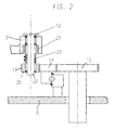
- einen vertikalen Teilschnitt durch den äußeren Umfangsbereich eines ersten Karussells der Inspektionsmaschine in Figur 1.
- Die in Figur 1 schematisch dargestellte Inspektionsmaschine ist speziell zum Inspizieren von gefüllten und verschlossenen Getränkeflaschen aus transparentem oder semitransparentem Material eingerichtet. Die zu überprüfenden Flaschen F werden beispielsweise von einer vorgeordneten Flaschenfüll- und Verschließmaschine über ein Einlaufförderband 1 kontinuierlich einem Einlaufsternrad 2 zugeführt, wobei sie spätestens vor der Übernahme durch das Einlaufsternrad 2 eine stationär angeordnete Einlaufkontrolle 9 passieren, die das Vorhandensein eines Verschlusses und ggf. auch die Füllhöhe überprüft. Zur Vermeidung von Verschmutzungen der Inspektionseinheiten durch überschwappende Flüssigkeit aus unverschlossenen Flaschen werden diese vom Einlaufsternrad 2 nicht erfasst und passieren es in tangentialer Richtung in Richtung einer nachgeordneten Sammelstelle. In gleicher Weise wird auch mit über- oder unterfüllten Flaschen verfahren.
- Das gegen den Uhrzeigersinn kontinuierlich antreibbare Einlaufsternrad 2 besitzt an seiner Peripherie eine Vielzahl von mit gleichmäßigem Maschinenteilungsabstand angeordnete, selektiv ansteuerbare, an unterschiedliche Flaschendurchmesser anpaßbare Greifklammern zum Erfassen der Flaschen am Rumpf- und ggf. auch Kopf- bzw. Halsbereich. Während dem Transfer vom Einlaufförderband 1 zu einem in Umlaufrichtung folgenden ersten Karussell 3 werden die Flaschen bodenfrei zunächst über eine stationäre Bodenabblaseinrichtung 10 zum Entfernen von Seifenschaum oder dgl., sowie eine danach angeordnete, im Hellfeldverfahren betreibbare Bodenkontrollstation 11 zum Erkennen von Verschmutzungen oder Schäden am Flaschenboden selbst, sowie auch schweren, durch Drehen der Flasche nicht aufwirbelbaren Fremdkörpern hinwegbewegt.
- Das Einlaufsternrad 2 kann beispielsweise entsprechend den europäischen Patenten 0 726 216 B1, 0 743 267 B1, die Bodenabblaseinrichtung 10 entsprechend dem deutschen Gebrauchsmuster 94 01 926 U1 und die Bodenkontrollstation 11 entsprechend der deutschen Patentanmeldung 101 33 104 ausgebildet sein.
- Im Berührpunkt der Teilkreise des Einlaufsternrads 2 und des ersten, im Uhrzeigersinn umlaufenden Karussells 3 werden die Flaschen F mit ihrer Bodenfläche auf um eine vertikale Achse im Karussell drehbar gelagerte Drehteller 12 übergeben und in einer axialen Einspannung drehbar gehalten, so wie das an sich aus dem gattungsbildenen Stand der Technik bekannt ist. Im weiteren Verlauf werden die auf den Drehtellern 12 aufrechtstehenden Flaschen zunächst beim Passieren des ersten Umlaufsektors A des Karussells 3 um ihre Hochachse kontinuierlich beschleunigt in Drehung versetzt, um anschließend den Umlaufsektor B mit einer definierten Höchstdrehzahl zu durchfahren, auf den ein Umlaufsektor C zum kontinuierlichen Abbremsen der Flaschendrehung annähernd bis zum Stillstand folgt.
- Zum Erzeugen der genannten Drehbewegungen der Drehteller 12 weist jeder Drehteller ein unten liegendes, auf seiner Welle 22 frei drehbar gelagertes Ritzel 13 auf, das mit der Innenverzahnung eines eine Innen- und Außenverzahnung aufweisenden Zahnkranzes 14 kämmt, der sich über eine mittenfreie Kugeldrehverbindung auf der Gestellplatte G der Maschine abstützt. Dieser Zahnkranz 14 ist durch ein in seine Außenverzahnung eingreifendes Antriebszahnrad 15 gesteuert von einem drehzahlveränderbaren Antrieb (Elektromotor oder dgl.) dem Uhrzeigersinn entgegengerichtet gegensinnig zum Karussell 3 antreibbar. Dieser Gegenlauf ermöglicht eine ausreichend hohe Rotation der Drehteller. Über nachfolgend noch in Verbindung mit der Fig. 2 genauer beschriebene steuerbare Magnetkupplungen sind die Wellen 22 beim Durchfahren der o.g. Umlaufsektoren A, B, C das übertragbare Drehmoment betreffend mehr oder weniger stark mit ihrem zugeordneten Ritzel 13 und im verbleibenden Umlaufsektor des Karussells 3 mit diesem selbst kuppelbar.
- An der Peripherie des ersten Karussells 3 befindet sich wenigstens eine Seitenwandkamera 16 und diametral gegenüberliegend an der äußeren Seite des Karussells 3 ein Seitenwandleuchtschirm 17. Bei dieser Anordnung handelt es sich um eine Hellfeldinspektion im Durchlicht, mit der Abdunkelungen hervorrufende Beschädigungen bzw. Verschmutzungen oder durch die rotierende Flüssigkeitsbewegung in den Flaschen aufgewirbelte lichtundurchlässige Schwebstoffe oder dgl. erkennbar sind.
- Den Endbereich des Drehsektors C des ersten Karussells 3 tangiert ein zweites Karussell 4, das - in gleicher weise wie das Einlaufsternrad 2 - an seiner Peripherie eine Vielzahl von mit dem Maschinenteilungsabstand versetzt angeordnete, selektiv steuerbare Greifzangen zum Erfassen der Flaschen an ihrem Rumpf- und ggf. auch Kopf- bzw. Halsbereich aufweist. Damit können die Flaschen F im gemeinsamen Beruhrpunkt zum ersten Karussell 3 erfasst und bodenfrei gegen den Uhrzeigersinn in Richtung zu einem darauffolgenden Sortiersternrad 5 transferiert werden, wobei während dem Weg dorthin die Flaschen einer Fremdkörpererkennung im Dunkelfeldverfahren unterzogen werden, mit der lichtstreuende Fremdkörper, insbesondere transparente Glassplitter, erkennbar sind.
- Zu diesem Zweck sind beiderseits der gekrümmten Umlaufbahn der Flaschen F an die Bahnkrümmung angepasste, äquidistante Leuchtschirme 18 und 19 stationär angeordnet, zwischen denen die Flaschen frei durchlaufen können und dabei seitlich möglichst großflächig beleuchtet werden. Durch die gleichzeitig erfolgende beidseitige, tunnelartige Beleuchtung ist eine sehr hohe Lichteinleitung in die Flaschen erreichbar, die insbesondere bei trüben oder dunklen Flüssigkeiten, wie z.B. hefehaltigem Bier oder Cola, von Vorteil ist. Die Leuchtschirme 18 und 19 können bevorzugt mit einer Vielzahl von LEDs bestückt sein, die durch eine Beleuchtungssteuerung gepulst betreibbar sind.
- Ferner ist das zweite Karussell 4 mit unterhalb seiner nicht dargestellten Greifzangen angeordneten Kameras 20 bestückt, beispielsweise jeweils einer Kamera pro Greifzange, die gemeinsam mit den Greifzangen stellungssynchron umlaufen und den Boden der beleuchteten Flaschen, ggf. über darunter schräg positionierte, nicht gezeigte Umlenkspiegel abbilden können. Mit dieser Anordnung wird eine Dunkelfeldbeleuchtung realisiert, in der lichtstreuende Fehler bzw. Fremdkörper in einer ansonsten dunklen Abbildung als helle Punkte oder Zonen aufscheinen.
- Alternativ wäre auch eine stationäre Anordnung einer oder mehrerer Kameras denkbar. Durch eine gleichzeitige Ansteuerung der Kameras 20 zur Bildaufnahme sowie der LEDs der Leuchtschirme 18 und 19 kann vorteilhafterweise eine sonst erforderliche Triggerung entfallen. Außerdem ist eine Abwandlung möglich, bei der über eine entsprechend angepaßte Spiegelanordnung eine Kamera immer mehrere Flaschenböden gleichzeitig erfassen und abbilden kann.
- Das ebenfalls mit selektiv steuerbaren, nicht dargestellten Greifzangen ausgestattete Sortiersternrad 5 ist in der Lage, die inspizierten Flaschen in Abhängigkeit der Prüfergebnisse der Bodenkontrollstation 11, der Seitenwandkamera 16 und der die Flaschen F durch den Boden betrachtenden Kameras 20 auf verschiedene Förderbänder abzugeben. So können beispielsweise die unbeanstandeten Flaschen die Inspektionsmaschine über das mit 6 bezeichnete Auslaufförderband verlassen, während Fehler aufweisende Flaschen in Abhängigkeit des erkannten Fehlers wahlweise auf die Ausschleusbänder 7 oder 8 ausleitbar sind.
- Aus der Fig. 2 ist der Antrieb der auf dem ersten Karussell 3 angeordneten Drehteller 12 im Detail erkennbar. Die Drehteller 12 sind jeweils am oberen Ende von auf einem gemeinsamen Teilkreis vertikal im Karussell 3 drehbar gelagerten Wellen 22 verdrehfest angeordnet. Auf jeder Welle 22 ist ein axial auf und ab verschiebbar geführter Magnetring 23 geführt, der mit seiner Welle 22 zur Drehmomentübertragung verdrehfest in Eingriff steht. Ferner ist koaxial zu jeder Welle 22 im Karussell 3 jeweils ein Hysteresering 27 verdrehfest angeordnet, dessen Innendurchmesser geringfügig größer ist als der Aussendurchmesser des Magnetrings 23. Mit axialem Abstand unterhalb des genannten ersten Hystereserings 27 ist in jedem der mit dem Zahnkranz 14 in Eingriff stehenden Ritzel 13 verdrehfest ein zweiter, einen den Aussendurchmesser des Magnetrings 23 ebenfalls geringfügig übersteigenden Innendurchmesser aufweisender Hysteresering 25 frei drehbar koaxial auf der Welle 22 gelagert. Der axiale Abstand der beiden Hystereseringe 25 und 27 entspricht annähernd der Höhe des Magnetrings 23, der zumindest an seinem oberen und unteren Rand umfänglich versetzt mit mehreren abwechselnd gegensätzlich gepolten Permanentmagneten bestückt ist. Die Hystereseringe bestehen aus einem Material hoher Permeabilität, z.B. Weicheisen.
- Jeder der Magnetringe 23 ist durch eine nicht näher dargestellte Betätigungseinrichtung, z.B. mechanische Kurvensteuerung, längs entlang der Welle 22 auf- und abverschiebbar und kann dadurch wahlweise mit dem antreibbaren untenliegenden Hysteresering 25 oder dem oberen verdrehfesten Hysteresering 27 eine Magnetkupplung bilden, wobei das übertragbare Drehmoment über die Eintauchtiefe, d.h. die axiale Überdeckung des Magnetrings 23 mit dem jeweils zugeordneten Hysteresering veränderbar ist. Die regulierbare Überdeckung ermöglicht eine einfache Steuerung der auf eine Flasche F übertragbaren Beschleunigungs- bzw.
- Bremsmomente in den einzelnen Umlaufsektoren des Karussells 3. Auf diese Weise kann jeder Drehteller 12 für sich unabhängig von den benachbarten Drehtellern ohne jeden elektrotechnischen Aufwand während eines Umlaufs mit dem Karussell zur momentanen Umlaufposition stellungsgerecht praktisch verschleißfrei bremsend oder beschleunigend drehmomentbeaufschlagt werden.
- Einzelne elektromotorische Antriebe für jeden Drehteller sind daher entbehrlich. Der Antrieb aller Drehteller 12 kann auf einfache Weise über den Zahnkranz 14 und das Antriebszahnrad 15 allein vom zentralen Maschinenantrieb abgeleitet werden, so dass automatisch auch eine Geschwindigkeits- und Drehstellungssyrichronisierung zu allen übrigen Bewegungsabläufen der Inspektionsmaschine gewährleistet ist.
- Davon abweichend ist aber auch ein eigener, vom Maschinenantrieb unabhängiger, drehzahlveränderlicher motorischer Antrieb einsetzbar, der das Antriebsrad 15 beaufschlagt.
Claims (8)
- Vorrichtung zum Inspizieren von gefüllten und verschlossenen Gefäßen bestehend aus einem Karussell (3) mit Antriebselementen (14, 15) zur Drehung der Gefäße um ihre Längsachse in dem die zu prüfenden Gefäße (F) derart um ihre Längsachse, in Drehung versetzbar sind, dass das Füllgut in den Gefäßen ausreichend schnell zu rotieren beginnt, um evtl. vorhandene Fremdkörper vom Gefäßboden aufzuwirbeln, und einem in Transportrichtung nachfolgenden zweiten Karussell (4) zum bodenfreien Gefäßtransport, dem wenigstens eine im Dunkelfeldverfahren arbeitende Inspektionseinrichtung (20) zur Erkennung lichtstreuender Fremdkörper im Füllgut zugeordnet ist, dadurch gekennzeichnet, dass beide Karussells (3,4) mit ihren Teilkreisen tangierend so nebeneinander angeordnet sind, dass die Gefäße (F) aus dem ersten Karussell (3) unmittelbar in das zweite Karussell (4) überführbar sind.
- Vorrichtung nach Anspruch 1, dadurch gekennzeichnet, dass dem ersten Karussell (3) in Transportrichtung gesehen ein die Gefäße bodenfrei transportierendes Sternrad (2) vorgeordnet ist, dem wenigstens eine Bodenabblaseinrichtung (10) und/oder eine im Hellfeldverfahren arbeitende Bodenkontrollstation (11) zugeordnet ist.
- Vorrichtung nach Anspruch 1 oder 2, dadurch gekennzeichnet, dass dem Sternrad (2) und/oder dem ersten Karussell (3) eine Einlaufkontrolle (9) zur Überprüfung der Füllstände und/oder der Gefäßverschlüsse vorgeordnet ist.
- Vorrichtung nach Anspruch 3, dadurch gekennzeichnet, dass unverschlossene Gefäße weder vom Sternrad (2) noch dem ersten Karussell (3) übernommen werden.
- Vorrichtung nach wenigstens einem der Ansprüche 1 bis 4, dadurch gekennzeichnet, dass das erste Karussell (3) auf einem Teilkreis mehrere antreibbare Drehteller (12) aufweist, die über steuerbare Magnetkupplungen (23,27) mit einem für alle Drehteller gemeinsamen Antriebselement (14,15) kraftschlüssig in oder außer Eingriff bringbar sind.
- Vorrichtung nach Anspruch 5, dadurch gekennzeichnet, dass die Magnetkupplungen (23,27) drehmomentveränderbare Hysteresekupplungen sind.
- Vorrichtung nach wenigstens einem der vorhergehenden Ansprüche 1 bis 6, dadurch gekennzeichnet, dass wenigstens abschnittsweise beiderseits der Umlaufbahn des zweiten Karussells (4) einander diametral gegenüberliegende, an die Bahnkrümmung äquidistant angepaßte Leuchtschirme (18,19) vorhanden sind, die die Gefäße (F) während einer Aufnahme des Bodens gleichzeitig seitlich beleuchten
- Vorrichtung nach Anspruch 7, dadurch gekennzeichnet, dass die Leuchtschirme (18,19) mit gepulst ansteuerbaren LBDs bestückt sind, die immer gleichzeitig mit einer Bodenaufnahme ansteuerbar sind.
Applications Claiming Priority (3)
| Application Number | Priority Date | Filing Date | Title |
|---|---|---|---|
| DE10257749A DE10257749B4 (de) | 2002-12-10 | 2002-12-10 | Vorrichtung zum Inspizieren von gefüllten und verschlossenen Gefäßen |
| DE10257749 | 2002-12-10 | ||
| PCT/EP2003/014062 WO2004053471A1 (de) | 2002-12-10 | 2003-12-10 | Vorrichtung zum inspizieren von gefüllten und verschlossenen gefässen |
Publications (2)
| Publication Number | Publication Date |
|---|---|
| EP1570256A1 EP1570256A1 (de) | 2005-09-07 |
| EP1570256B1 true EP1570256B1 (de) | 2006-07-05 |
Family
ID=32477535
Family Applications (1)
| Application Number | Title | Priority Date | Filing Date |
|---|---|---|---|
| EP03789220A Expired - Lifetime EP1570256B1 (de) | 2002-12-10 | 2003-12-10 | Vorrichtung zum inspizieren von gefüllten und verschlossenen gefässen |
Country Status (7)
| Country | Link |
|---|---|
| US (1) | US7295317B2 (de) |
| EP (1) | EP1570256B1 (de) |
| JP (2) | JP4578978B2 (de) |
| AT (1) | ATE332499T1 (de) |
| AU (1) | AU2003293836A1 (de) |
| DE (2) | DE10257749B4 (de) |
| WO (1) | WO2004053471A1 (de) |
Cited By (1)
| Publication number | Priority date | Publication date | Assignee | Title |
|---|---|---|---|---|
| EP2383567A1 (de) | 2010-04-29 | 2011-11-02 | Krones AG | Schwebstofferkennung in mit Flüssigkeit befüllten Behältnissen |
Families Citing this family (30)
| Publication number | Priority date | Publication date | Assignee | Title |
|---|---|---|---|---|
| CN100582758C (zh) * | 2005-11-03 | 2010-01-20 | 清华大学 | 用快中子和连续能谱x射线进行材料识别的方法及其装置 |
| DE102006009282B8 (de) * | 2006-03-01 | 2010-12-09 | Khs Gmbh | Vorrichtung zum Einbringen einer Inspektions- und/oder Kontrollflüssigkeit in Flaschen oder dergleichen Behälter |
| JP5159237B2 (ja) * | 2006-10-23 | 2013-03-06 | エムハート・グラス・ソシエテ・アノニム | ガラス容器を検査する装置 |
| JP5425387B2 (ja) * | 2006-10-23 | 2014-02-26 | エムハート・グラス・ソシエテ・アノニム | ガラス容器を検査するための機械 |
| DE102006062298B3 (de) * | 2006-12-27 | 2008-06-19 | Krones Ag | Vorrichtung und Verfahren zum Inspizieren von Behältnissen |
| DE102006062575B3 (de) * | 2006-12-29 | 2008-03-27 | Krones Ag | Vorrichtung und Verfahren zum Inspizieren von Behältnisböden |
| DE102007025524B4 (de) * | 2007-05-31 | 2010-07-29 | Khs Ag | Opto-elektrisches Erfassungssystem |
| DE102007030917B4 (de) | 2007-07-03 | 2023-01-26 | Khs Gmbh | Verfahren sowie System zum Behandeln von Flaschen oder dergleichen Behälter sowie Flaschen bzw. Behälter zur Verwendung bei diesem Verfahren oder System |
| DE102009035585A1 (de) | 2009-07-31 | 2011-02-03 | Krones Ag | Inspektionsvorrichtung und Inspektionsverfahren zum Erkennen von Fremdkörpern in einem gefüllten Behälter |
| US8287270B2 (en) | 2009-09-30 | 2012-10-16 | Printpack Illinois Inc. | Methods and systems for thermoforming with billets |
| DE102009058219A1 (de) * | 2009-12-15 | 2011-06-16 | Till, Volker, Dipl.-Ing. | Anlage zum Bedrucken von Behältern |
| DE102010012570B4 (de) | 2010-03-23 | 2024-08-14 | Krones Aktiengesellschaft | Vorrichtung und Verfahren zum Untersuchen von befüllten Behältnissen auf Fremdkörper |
| JP5651085B2 (ja) * | 2011-08-22 | 2015-01-07 | 株式会社 日立産業制御ソリューションズ | 異物検査装置 |
| DE102011083037A1 (de) * | 2011-09-20 | 2013-03-21 | Krones Aktiengesellschaft | Verfahren und Vorrichtung zur Inspektion von Behältern und Vorformlingen |
| CN102507603A (zh) * | 2011-10-27 | 2012-06-20 | 西安毅达信息系统有限公司 | 液体可见异物自动检测机用电磁吸附跟踪机构 |
| CN102507604B (zh) * | 2011-10-27 | 2013-09-11 | 西安毅达信息系统有限公司 | 液体可见异物自动检测机 |
| DE102011086099A1 (de) | 2011-11-10 | 2013-05-16 | Krones Aktiengesellschaft | Inspektion und Rückführung von Behältern |
| DE102013201798A1 (de) | 2013-02-05 | 2014-08-07 | Krones Ag | Fremdkörperinspektion in gefüllten Behältern |
| CN105834116A (zh) * | 2016-04-29 | 2016-08-10 | 深圳市华腾半导体设备有限公司 | 一种转移式分类的高速分选方法 |
| IT201700032261A1 (it) * | 2017-03-23 | 2018-09-23 | Antares Vision S R L | Macchina ispezionatrice |
| CN109596850A (zh) * | 2017-09-30 | 2019-04-09 | 深圳迈瑞生物医疗电子股份有限公司 | 样本装载盘的控制方法及样本分析仪 |
| CN108405357B (zh) * | 2018-04-03 | 2024-11-12 | 广州市博仕机电工贸有限公司 | 一种自动在线瓶胚全向视检机 |
| CA3183636A1 (en) * | 2020-08-07 | 2022-02-10 | G.D S.P.A. | Control method in a production process for articles and a production apparatus for articles operating according to this method |
| JP7676941B2 (ja) * | 2021-05-19 | 2025-05-15 | 日本電気硝子株式会社 | 微小物体の検査方法 |
| DE102021112925A1 (de) | 2021-05-19 | 2022-11-24 | Krones Aktiengesellschaft | Vorrichtung und Verfahren zur Behandlung und/oder Inspektion von Behältern |
| CN114184620A (zh) * | 2021-12-31 | 2022-03-15 | 欧普照明股份有限公司 | 液态食物杂质的检测装置及检测方法 |
| CN115650145B (zh) * | 2022-10-25 | 2023-05-05 | 湖北长联杜勒制药有限公司 | 一种氨基酸注射液灌封装置 |
| KR20250052586A (ko) * | 2023-10-12 | 2025-04-21 | 제이더블유홀딩스 주식회사 | 시린지 검사 장치 |
| DE102023133768A1 (de) * | 2023-12-04 | 2025-06-05 | Heuft Systemtechnik Gmbh | Inspektionsvorrichtung für Behälter |
| KR102916538B1 (ko) | 2024-11-22 | 2026-01-21 | 국립한밭대학교 산학협력단 | 의약 용기의 품질 검사를 위한 머신 비전을 적용한 다중 카메라 인라인 검사 시스템 및 그 방법 |
Family Cites Families (27)
| Publication number | Priority date | Publication date | Assignee | Title |
|---|---|---|---|---|
| JPS5219798B2 (de) * | 1971-12-22 | 1977-05-30 | ||
| US3900266A (en) * | 1972-10-31 | 1975-08-19 | Eisai Co Ltd | Method and apparatus for detecting solid substances contained in liquid |
| JPS5120897A (en) | 1974-08-13 | 1976-02-19 | Nippon Electron Optics Lab | Anpuru baiarutono kensahoshiki |
| US4417662A (en) * | 1981-05-04 | 1983-11-29 | Eli Lilly And Company | Vial inspection machine |
| JPH0312063Y2 (de) * | 1984-09-18 | 1991-03-22 | ||
| DD239394A1 (de) * | 1985-07-19 | 1986-09-24 | Nagema Veb K | Einrichtung zur betriebsdatenerfassung an fuell- und verschliessmaschinen |
| EP0277629B1 (de) * | 1987-02-04 | 1993-05-05 | Harro Höfliger Verpackungsmaschinen GmbH | Verfahren und Vorrichtung zum Feststellen von Fremdkörpern in Fluiden |
| JP3050557B2 (ja) * | 1989-01-25 | 2000-06-12 | エーザイ株式会社 | 被検査物に対する検査方向の方向規制装置及びそれを含む異物検査装置並びに異物検査装置の検光面 |
| JPH0448251A (ja) * | 1990-06-18 | 1992-02-18 | Asahi Chem Ind Co Ltd | 瓶検査装置 |
| DE4239203C2 (de) * | 1992-04-07 | 1995-12-07 | Rudolf Zodrow | Bügelflascheninspektionsmaschine |
| DE4200798C2 (de) * | 1992-01-15 | 1994-08-18 | Rudolf Zodrow | Flascheninspektionsmaschine |
| JPH0627044A (ja) * | 1992-07-10 | 1994-02-04 | Shibuya Kogyo Co Ltd | 充填容器の異物検査方法およびその装置 |
| IT1260385B (it) * | 1992-10-05 | 1996-04-05 | Procedimento per ispezionare contenitori in materiale trasparente e il liquido in essi contenuto, per rilevare eventuali difetti dei contenitori od impurita' nel liquido, e impianto che realizza detto procedimento. | |
| DE9401926U1 (de) * | 1994-02-05 | 1994-03-31 | Krones Ag Hermann Kronseder Maschinenfabrik, 93073 Neutraubling | Abblasvorrichtung für den Flaschenboden in Flascheninspektionsmaschinen |
| JP3351910B2 (ja) * | 1994-09-01 | 2002-12-03 | エーザイ株式会社 | バイアル瓶の検査方法と装置 |
| JPH08159989A (ja) * | 1994-12-06 | 1996-06-21 | Datsuku Eng Kk | 液体密封容器の検査方法および検査装置 |
| ES2124956T3 (es) * | 1995-02-07 | 1999-02-16 | Hermann Kronseder | Estrella de transporte para recipientes. |
| ES2129902T3 (es) * | 1995-05-13 | 1999-06-16 | Hermann Kronseder | Rueda transportadora en estrella para recipientes. |
| JP3295628B2 (ja) * | 1997-10-22 | 2002-06-24 | 学校法人立命館 | 異物検出方法及び異物検出装置 |
| US5969810A (en) * | 1998-05-14 | 1999-10-19 | Owens-Brockway Glass Container Inc. | Optical inspection of transparent containers using two cameras and a single light source |
| JP3162014B2 (ja) * | 1998-05-25 | 2001-04-25 | 日精株式会社 | 容器内の液中異物検査装置 |
| JP3340413B2 (ja) * | 2000-01-20 | 2002-11-05 | 株式会社スキャンテクノロジー | ペットボトル内沈殿異物検査方法及びその装置 |
| DE10017126C1 (de) * | 2000-04-06 | 2001-06-13 | Krones Ag | Verfahren und Vorrichtung zum optischen Überprüfen transparenter Behälter |
| JP4516201B2 (ja) | 2000-11-01 | 2010-08-04 | リッカーマン(日本)株式会社 | 連続検査装置 |
| DE10164058B4 (de) * | 2000-12-30 | 2008-06-12 | Krones Ag | Inspektionsvorrichtung |
| DE10133104C2 (de) * | 2001-07-12 | 2003-06-26 | Krones Ag | Vorrichtung und Verfahren zur Inspektion transparenter Böden von gefüllten und/oder verschlossenen Flaschen |
| JP4101555B2 (ja) * | 2002-05-13 | 2008-06-18 | 株式会社スキャンテクノロジー | 異物検査装置 |
-
2002
- 2002-12-10 DE DE10257749A patent/DE10257749B4/de not_active Expired - Lifetime
-
2003
- 2003-12-10 DE DE50304171T patent/DE50304171D1/de not_active Expired - Lifetime
- 2003-12-10 EP EP03789220A patent/EP1570256B1/de not_active Expired - Lifetime
- 2003-12-10 WO PCT/EP2003/014062 patent/WO2004053471A1/de not_active Ceased
- 2003-12-10 US US10/507,473 patent/US7295317B2/en not_active Expired - Lifetime
- 2003-12-10 AT AT03789220T patent/ATE332499T1/de active
- 2003-12-10 JP JP2004558066A patent/JP4578978B2/ja not_active Expired - Fee Related
- 2003-12-10 AU AU2003293836A patent/AU2003293836A1/en not_active Abandoned
-
2010
- 2010-05-20 JP JP2010116318A patent/JP4995303B2/ja not_active Expired - Fee Related
Cited By (3)
| Publication number | Priority date | Publication date | Assignee | Title |
|---|---|---|---|---|
| EP2383567A1 (de) | 2010-04-29 | 2011-11-02 | Krones AG | Schwebstofferkennung in mit Flüssigkeit befüllten Behältnissen |
| DE102010018823A1 (de) | 2010-04-29 | 2011-11-03 | Krones Ag | Schwebstofferkennung in mit Flüssigkeit befüllten Behältnissen |
| DE102010018823B4 (de) | 2010-04-29 | 2021-09-23 | Krones Aktiengesellschaft | Schwebstofferkennung in mit Flüssigkeit befüllten Behältnissen |
Also Published As
| Publication number | Publication date |
|---|---|
| JP4578978B2 (ja) | 2010-11-10 |
| EP1570256A1 (de) | 2005-09-07 |
| DE10257749B4 (de) | 2006-05-04 |
| JP4995303B2 (ja) | 2012-08-08 |
| ATE332499T1 (de) | 2006-07-15 |
| DE10257749A1 (de) | 2004-07-08 |
| US7295317B2 (en) | 2007-11-13 |
| JP2010249827A (ja) | 2010-11-04 |
| US20050248766A1 (en) | 2005-11-10 |
| DE50304171D1 (de) | 2006-08-17 |
| JP2006509207A (ja) | 2006-03-16 |
| WO2004053471A1 (de) | 2004-06-24 |
| AU2003293836A1 (en) | 2004-06-30 |
Similar Documents
| Publication | Publication Date | Title |
|---|---|---|
| EP1570256B1 (de) | Vorrichtung zum inspizieren von gefüllten und verschlossenen gefässen | |
| DE4214958C2 (de) | Kontinuierlich arbeitende Inspektionsmaschine für Gefäße | |
| EP1939630B1 (de) | Vorrichtung und Verfahren zum Inspizieren von Behältnissen | |
| DE102010018823B4 (de) | Schwebstofferkennung in mit Flüssigkeit befüllten Behältnissen | |
| DE3236901C2 (de) | ||
| EP1531433B1 (de) | Rücknahmeautomat für Behältnisse | |
| EP0894544B1 (de) | Inspektionsmaschine zum Prüfen von Flaschen oder dgl. | |
| DE2201103A1 (de) | Vorrichtung zum Befoerdern aufeinanderfolgender Arzneikapseln u.dgl. zu einer Behandlungs- bzw. Pruefstelle in einer vorbestimmten Stellung und Orientierung | |
| WO2015067406A1 (de) | Verfahren sowie behälterbehandlungsmaschine zum behandeln von behältern | |
| WO2019048114A1 (de) | Inspektionsvorrichtung und verfahren zur erkennung von fremdkörpern in behältern | |
| DE102005057872B4 (de) | Inspektionsmaschine | |
| DE69101301T2 (de) | Anordnung zum synchronen Antrieb von Einrichtungen zur Füllung und Containerbehandlung in Getränkeabfüllern. | |
| EP2720036B1 (de) | Vorrichtung zur Prüfung von Erzeugnissen | |
| DE69426514T2 (de) | Anordnung zur Kontrolle von Hohlglasbehältern | |
| DE19703528B4 (de) | Verfahren und Vorrichtung zur Dichtigkeitsprüfung von verschlossenen Flaschen o. dgl. | |
| DE19710820A1 (de) | Zentrifugalsortierer | |
| DE10163846A1 (de) | Vorrichtung zur Röntgen-Prüfung eines Rades | |
| DE1473343C (de) | Prüfmaschine fur Glasbehälter | |
| EP4455036A1 (de) | Vorrichtung vom rundläufer-typ zum abfüllen von einem füllmedium in eine vielzahl von behälter | |
| EP4458700A1 (de) | Vorrichtung vom rundläufer-typ zum abfüllen von einem füllmedium in eine vielzahl von behälter | |
| DE102023110385A1 (de) | Vorrichtung vom rundläufer-typ zum abfüllen von einem füllmedium in eine vielzahl von behälter | |
| DE102021112925A1 (de) | Vorrichtung und Verfahren zur Behandlung und/oder Inspektion von Behältern | |
| DE1473343B2 (de) | Pruefmaschine fuer glasbehaelter |
Legal Events
| Date | Code | Title | Description |
|---|---|---|---|
| PUAI | Public reference made under article 153(3) epc to a published international application that has entered the european phase |
Free format text: ORIGINAL CODE: 0009012 |
|
| 17P | Request for examination filed |
Effective date: 20040528 |
|
| AK | Designated contracting states |
Kind code of ref document: A1 Designated state(s): AT BE BG CH CY CZ DE DK EE ES FI FR GB GR HU IE IT LI LU MC NL PT RO SE SI SK TR |
|
| AX | Request for extension of the european patent |
Extension state: AL LT LV MK |
|
| GRAP | Despatch of communication of intention to grant a patent |
Free format text: ORIGINAL CODE: EPIDOSNIGR1 |
|
| DAX | Request for extension of the european patent (deleted) | ||
| GRAS | Grant fee paid |
Free format text: ORIGINAL CODE: EPIDOSNIGR3 |
|
| GRAA | (expected) grant |
Free format text: ORIGINAL CODE: 0009210 |
|
| AK | Designated contracting states |
Kind code of ref document: B1 Designated state(s): AT BE BG CH CY CZ DE DK EE ES FI FR GB GR HU IE IT LI LU MC NL PT RO SE SI SK TR |
|
| PG25 | Lapsed in a contracting state [announced via postgrant information from national office to epo] |
Ref country code: SI Free format text: LAPSE BECAUSE OF FAILURE TO SUBMIT A TRANSLATION OF THE DESCRIPTION OR TO PAY THE FEE WITHIN THE PRESCRIBED TIME-LIMIT Effective date: 20060705 Ref country code: FI Free format text: LAPSE BECAUSE OF FAILURE TO SUBMIT A TRANSLATION OF THE DESCRIPTION OR TO PAY THE FEE WITHIN THE PRESCRIBED TIME-LIMIT Effective date: 20060705 Ref country code: IE Free format text: LAPSE BECAUSE OF FAILURE TO SUBMIT A TRANSLATION OF THE DESCRIPTION OR TO PAY THE FEE WITHIN THE PRESCRIBED TIME-LIMIT Effective date: 20060705 Ref country code: CZ Free format text: LAPSE BECAUSE OF FAILURE TO SUBMIT A TRANSLATION OF THE DESCRIPTION OR TO PAY THE FEE WITHIN THE PRESCRIBED TIME-LIMIT Effective date: 20060705 Ref country code: SK Free format text: LAPSE BECAUSE OF FAILURE TO SUBMIT A TRANSLATION OF THE DESCRIPTION OR TO PAY THE FEE WITHIN THE PRESCRIBED TIME-LIMIT Effective date: 20060705 Ref country code: RO Free format text: LAPSE BECAUSE OF FAILURE TO SUBMIT A TRANSLATION OF THE DESCRIPTION OR TO PAY THE FEE WITHIN THE PRESCRIBED TIME-LIMIT Effective date: 20060705 |
|
| REG | Reference to a national code |
Ref country code: GB Ref legal event code: FG4D Free format text: NOT ENGLISH |
|
| REG | Reference to a national code |
Ref country code: CH Ref legal event code: EP |
|
| REG | Reference to a national code |
Ref country code: CH Ref legal event code: NV Representative=s name: PATENTANWALTSBUERO JEAN HUNZIKER |
|
| REG | Reference to a national code |
Ref country code: IE Ref legal event code: FG4D Free format text: LANGUAGE OF EP DOCUMENT: GERMAN |
|
| REF | Corresponds to: |
Ref document number: 50304171 Country of ref document: DE Date of ref document: 20060817 Kind code of ref document: P |
|
| GBT | Gb: translation of ep patent filed (gb section 77(6)(a)/1977) |
Effective date: 20060911 |
|
| PG25 | Lapsed in a contracting state [announced via postgrant information from national office to epo] |
Ref country code: DK Free format text: LAPSE BECAUSE OF FAILURE TO SUBMIT A TRANSLATION OF THE DESCRIPTION OR TO PAY THE FEE WITHIN THE PRESCRIBED TIME-LIMIT Effective date: 20061005 Ref country code: BG Free format text: LAPSE BECAUSE OF FAILURE TO SUBMIT A TRANSLATION OF THE DESCRIPTION OR TO PAY THE FEE WITHIN THE PRESCRIBED TIME-LIMIT Effective date: 20061005 Ref country code: SE Free format text: LAPSE BECAUSE OF FAILURE TO SUBMIT A TRANSLATION OF THE DESCRIPTION OR TO PAY THE FEE WITHIN THE PRESCRIBED TIME-LIMIT Effective date: 20061005 |
|
| PG25 | Lapsed in a contracting state [announced via postgrant information from national office to epo] |
Ref country code: ES Free format text: LAPSE BECAUSE OF FAILURE TO SUBMIT A TRANSLATION OF THE DESCRIPTION OR TO PAY THE FEE WITHIN THE PRESCRIBED TIME-LIMIT Effective date: 20061016 |
|
| PG25 | Lapsed in a contracting state [announced via postgrant information from national office to epo] |
Ref country code: PT Free format text: LAPSE BECAUSE OF FAILURE TO SUBMIT A TRANSLATION OF THE DESCRIPTION OR TO PAY THE FEE WITHIN THE PRESCRIBED TIME-LIMIT Effective date: 20061205 |
|
| ET | Fr: translation filed | ||
| PG25 | Lapsed in a contracting state [announced via postgrant information from national office to epo] |
Ref country code: MC Free format text: LAPSE BECAUSE OF NON-PAYMENT OF DUE FEES Effective date: 20061231 |
|
| REG | Reference to a national code |
Ref country code: IE Ref legal event code: FD4D |
|
| PLBE | No opposition filed within time limit |
Free format text: ORIGINAL CODE: 0009261 |
|
| STAA | Information on the status of an ep patent application or granted ep patent |
Free format text: STATUS: NO OPPOSITION FILED WITHIN TIME LIMIT |
|
| 26N | No opposition filed |
Effective date: 20070410 |
|
| PG25 | Lapsed in a contracting state [announced via postgrant information from national office to epo] |
Ref country code: GR Free format text: LAPSE BECAUSE OF FAILURE TO SUBMIT A TRANSLATION OF THE DESCRIPTION OR TO PAY THE FEE WITHIN THE PRESCRIBED TIME-LIMIT Effective date: 20061006 |
|
| PG25 | Lapsed in a contracting state [announced via postgrant information from national office to epo] |
Ref country code: EE Free format text: LAPSE BECAUSE OF FAILURE TO SUBMIT A TRANSLATION OF THE DESCRIPTION OR TO PAY THE FEE WITHIN THE PRESCRIBED TIME-LIMIT Effective date: 20060705 |
|
| PG25 | Lapsed in a contracting state [announced via postgrant information from national office to epo] |
Ref country code: TR Free format text: LAPSE BECAUSE OF FAILURE TO SUBMIT A TRANSLATION OF THE DESCRIPTION OR TO PAY THE FEE WITHIN THE PRESCRIBED TIME-LIMIT Effective date: 20060705 Ref country code: LU Free format text: LAPSE BECAUSE OF NON-PAYMENT OF DUE FEES Effective date: 20061210 Ref country code: HU Free format text: LAPSE BECAUSE OF FAILURE TO SUBMIT A TRANSLATION OF THE DESCRIPTION OR TO PAY THE FEE WITHIN THE PRESCRIBED TIME-LIMIT Effective date: 20070106 |
|
| PG25 | Lapsed in a contracting state [announced via postgrant information from national office to epo] |
Ref country code: CY Free format text: LAPSE BECAUSE OF FAILURE TO SUBMIT A TRANSLATION OF THE DESCRIPTION OR TO PAY THE FEE WITHIN THE PRESCRIBED TIME-LIMIT Effective date: 20060705 |
|
| PGFP | Annual fee paid to national office [announced via postgrant information from national office to epo] |
Ref country code: CH Payment date: 20121213 Year of fee payment: 10 |
|
| PGFP | Annual fee paid to national office [announced via postgrant information from national office to epo] |
Ref country code: AT Payment date: 20121127 Year of fee payment: 10 |
|
| PGFP | Annual fee paid to national office [announced via postgrant information from national office to epo] |
Ref country code: BE Payment date: 20121217 Year of fee payment: 10 |
|
| BERE | Be: lapsed |
Owner name: *KRONES A.G. Effective date: 20131231 |
|
| REG | Reference to a national code |
Ref country code: CH Ref legal event code: PL |
|
| REG | Reference to a national code |
Ref country code: AT Ref legal event code: MM01 Ref document number: 332499 Country of ref document: AT Kind code of ref document: T Effective date: 20131210 |
|
| PG25 | Lapsed in a contracting state [announced via postgrant information from national office to epo] |
Ref country code: LI Free format text: LAPSE BECAUSE OF NON-PAYMENT OF DUE FEES Effective date: 20131231 Ref country code: BE Free format text: LAPSE BECAUSE OF NON-PAYMENT OF DUE FEES Effective date: 20131231 Ref country code: CH Free format text: LAPSE BECAUSE OF NON-PAYMENT OF DUE FEES Effective date: 20131231 |
|
| PG25 | Lapsed in a contracting state [announced via postgrant information from national office to epo] |
Ref country code: AT Free format text: LAPSE BECAUSE OF NON-PAYMENT OF DUE FEES Effective date: 20131210 |
|
| REG | Reference to a national code |
Ref country code: FR Ref legal event code: PLFP Year of fee payment: 13 |
|
| PGFP | Annual fee paid to national office [announced via postgrant information from national office to epo] |
Ref country code: GB Payment date: 20151209 Year of fee payment: 13 Ref country code: DE Payment date: 20151201 Year of fee payment: 13 |
|
| PGFP | Annual fee paid to national office [announced via postgrant information from national office to epo] |
Ref country code: FR Payment date: 20151110 Year of fee payment: 13 Ref country code: NL Payment date: 20151210 Year of fee payment: 13 |
|
| PGFP | Annual fee paid to national office [announced via postgrant information from national office to epo] |
Ref country code: IT Payment date: 20151221 Year of fee payment: 13 |
|
| REG | Reference to a national code |
Ref country code: DE Ref legal event code: R119 Ref document number: 50304171 Country of ref document: DE |
|
| REG | Reference to a national code |
Ref country code: NL Ref legal event code: MM Effective date: 20170101 |
|
| GBPC | Gb: european patent ceased through non-payment of renewal fee |
Effective date: 20161210 |
|
| PG25 | Lapsed in a contracting state [announced via postgrant information from national office to epo] |
Ref country code: NL Free format text: LAPSE BECAUSE OF NON-PAYMENT OF DUE FEES Effective date: 20170101 |
|
| REG | Reference to a national code |
Ref country code: FR Ref legal event code: ST Effective date: 20170831 |
|
| PG25 | Lapsed in a contracting state [announced via postgrant information from national office to epo] |
Ref country code: IT Free format text: LAPSE BECAUSE OF NON-PAYMENT OF DUE FEES Effective date: 20161210 Ref country code: FR Free format text: LAPSE BECAUSE OF NON-PAYMENT OF DUE FEES Effective date: 20170102 |
|
| PG25 | Lapsed in a contracting state [announced via postgrant information from national office to epo] |
Ref country code: DE Free format text: LAPSE BECAUSE OF NON-PAYMENT OF DUE FEES Effective date: 20170701 Ref country code: GB Free format text: LAPSE BECAUSE OF NON-PAYMENT OF DUE FEES Effective date: 20161210 |