EP2720036B1 - Vorrichtung zur Prüfung von Erzeugnissen - Google Patents
Vorrichtung zur Prüfung von Erzeugnissen Download PDFInfo
- Publication number
- EP2720036B1 EP2720036B1 EP13004521.4A EP13004521A EP2720036B1 EP 2720036 B1 EP2720036 B1 EP 2720036B1 EP 13004521 A EP13004521 A EP 13004521A EP 2720036 B1 EP2720036 B1 EP 2720036B1
- Authority
- EP
- European Patent Office
- Prior art keywords
- products
- transport
- accordance
- inspection
- carousel
- Prior art date
- Legal status (The legal status is an assumption and is not a legal conclusion. Google has not performed a legal analysis and makes no representation as to the accuracy of the status listed.)
- Active
Links
Images


Classifications
-
- G—PHYSICS
- G01—MEASURING; TESTING
- G01N—INVESTIGATING OR ANALYSING MATERIALS BY DETERMINING THEIR CHEMICAL OR PHYSICAL PROPERTIES
- G01N27/00—Investigating or analysing materials by the use of electric, electrochemical, or magnetic means
- G01N27/92—Investigating or analysing materials by the use of electric, electrochemical, or magnetic means by investigating breakdown voltage
-
- G—PHYSICS
- G01—MEASURING; TESTING
- G01N—INVESTIGATING OR ANALYSING MATERIALS BY DETERMINING THEIR CHEMICAL OR PHYSICAL PROPERTIES
- G01N35/00—Automatic analysis not limited to methods or materials provided for in any single one of groups G01N1/00 - G01N33/00; Handling materials therefor
- G01N35/02—Automatic analysis not limited to methods or materials provided for in any single one of groups G01N1/00 - G01N33/00; Handling materials therefor using a plurality of sample containers moved by a conveyor system past one or more treatment or analysis stations
- G01N35/04—Details of the conveyor system
-
- B—PERFORMING OPERATIONS; TRANSPORTING
- B65—CONVEYING; PACKING; STORING; HANDLING THIN OR FILAMENTARY MATERIAL
- B65G—TRANSPORT OR STORAGE DEVICES, e.g. CONVEYORS FOR LOADING OR TIPPING, SHOP CONVEYOR SYSTEMS OR PNEUMATIC TUBE CONVEYORS
- B65G2201/00—Indexing codes relating to handling devices, e.g. conveyors, characterised by the type of product or load being conveyed or handled
- B65G2201/02—Articles
- B65G2201/0235—Containers
- B65G2201/0244—Bottles
-
- B—PERFORMING OPERATIONS; TRANSPORTING
- B65—CONVEYING; PACKING; STORING; HANDLING THIN OR FILAMENTARY MATERIAL
- B65G—TRANSPORT OR STORAGE DEVICES, e.g. CONVEYORS FOR LOADING OR TIPPING, SHOP CONVEYOR SYSTEMS OR PNEUMATIC TUBE CONVEYORS
- B65G29/00—Rotary conveyors, e.g. rotating discs, arms, star-wheels or cones
- B65G29/02—Rotary conveyors, e.g. rotating discs, arms, star-wheels or cones for inclined or vertical transit
-
- G—PHYSICS
- G01—MEASURING; TESTING
- G01N—INVESTIGATING OR ANALYSING MATERIALS BY DETERMINING THEIR CHEMICAL OR PHYSICAL PROPERTIES
- G01N35/00—Automatic analysis not limited to methods or materials provided for in any single one of groups G01N1/00 - G01N33/00; Handling materials therefor
- G01N35/02—Automatic analysis not limited to methods or materials provided for in any single one of groups G01N1/00 - G01N33/00; Handling materials therefor using a plurality of sample containers moved by a conveyor system past one or more treatment or analysis stations
- G01N35/04—Details of the conveyor system
- G01N2035/0439—Rotary sample carriers, i.e. carousels
Definitions
- the invention relates to a device for testing products according to the preamble of claim 1.
- inspection machines For inspection of products such as ampoules, bottles, cylinder ampoules, vials or the like inspection machines are usually used. The inspection is usually done optically. For liquid, freeze-dried and opaque products, particle inspection and inspection of cosmetic defects is performed in one machine. With these optical inspection methods for liquid products, particles, suspended particles, fibers, the glass and the level can be inspected. In the case of freeze-dried products, the so-called “meltback", a sunken cake, discoloration, impurities on cake, non-freeze-dried product and the fill level can be checked.
- the location and color of the flip-off cap, the color of the crimp cap, the presence of an optional rubber stopper, the quality of the crimp, dents and scratches in the crimp cap, cracks and scratches in the sidewall and in the floor, and soiling can be detected.
- JP56133654 describes a test device for ampoules, are supplied to the test ampoules in horizontal alignment via a screw conveyor two successively arranged transport stars to pass the samples to an inspection carousel. During the entire transport and testing process, the horizontal orientation of the ampoules to be tested is not changed.
- document FR2499952 describes an arrangement of two transporting stars for tilting or erecting bottles in a beverage filling plant.
- the bottles are thereby tilted or erected by the inclination of the two transport stars to each other and the force acting on the bottles gravity.
- This prior art pivoting mechanism is structurally complex and leads to a relatively high maintenance.
- the object of the invention is to develop a generic device for testing products such that the optical inspection downstream high-voltage testing of the products to be tested can be done in a simple and secure manner, the arrival and removal of the products to be inspected should be simplified.
- an apparatus for testing products in particular ampoules, bottles and the like, provided with means for moving the products to be tested and with detection means for high-voltage testing for the products, which has a rotatable drivable inspection carousel.
- the products are transferable by means of at least two obliquely arranged to each other rotating transport stars from a vertical receiving position in which the products are transported, in an at least horizontal test position. From this horizontal test position they are in turn via two obliquely arranged to each other rotating transport stars in a vertical delivery position can be transferred.
- this inventively provided inspection carousel with appropriate supply and discharge products on their transport which is followed by the optical inspection, are quickly and continuously accepted and after the change in position from vertical to horizontal state by the obliquely arranged rotating transport stars in the horizontal Test position in the inspection carousel to be handed over. In this horizontal test position they are checked before they are pivoted back to a vertical dispensing position, then, depending on the test result either as defective product to be discharged or discharged as a so-called good product after passing high-voltage test and then packaged.
- the inspection carousel may be assigned a transport star arranged vertically with respect to the feed plane of the products.
- a first transport star can receive the continuously conveyed vertically standing products and, due to its inclination, pass obliquely to the adjacently arranged transport star, which tilts these products further by its further inclined inclination and can finally transfer them to the further transport star arranged perpendicular to the feed plane. which now transfers the products in a horizontal position to the inspection carousel. After passing through the inspection carousel, the products can be transferred to a transport star, which is likewise arranged perpendicularly to the feed plane and from which the products can then be dispensed vertically by further transport via two obliquely arranged transport stars.
- each obliquely arranged transport star can continuous acquisition and transfer of the products in a very simple, compact and less prone to failure construction can be achieved.
- the products may then be receivable in the inspection carousel between slidable lower and upper holders.
- the holders may advantageously be designed as rotational axis lower parts and rotational axis upper parts, between which the products can be coupled in, that is to say clamped in, for example.
- the products are usually rotatable in the coupled state between the rotation axis lower parts and the rotational axis upper parts about its own axis.
- the electrodes for high-voltage testing and preferably in each case the associated ground and needle electrodes, are arranged in the inspection carousel, so that the products are guided past the respective electrodes during transport through the inspection stand.
- the respective holders that is to say the rotational axis lower parts and rotational axis upper parts, are advantageously mounted so as to be displaceable in the inspection carousel via a stroke curve adjustment.
- a first stroke curve adjustment can bring about a delivery of the rotational axis lower parts and a second Hubkurvenver ein a delivery of Rotationsachsenoberermaschine.
- a third lift curve adjustment may be provided to allow for product size-dependent presetting of the rotary top shells. As a result, different sized products can be included in the inspection carousel if necessary.
- the transport stars are designed as suction stars.
- the corresponding products so for example, the ampoules or bottles can be kept safe in the transport star during their transport, recorded in a very safe manner and also discharged again.
- a belt drive may preferably be provided.
- the products to be inspected can be fed continuously via a screw conveyor to the testing device.
- the products discharged from the testing device can be transported away continuously with a corresponding second transport screw.
- FIG. 1 a device 10 for testing products, in particular of ampoules, cylindrical ampoules, bottles, vials or the like is shown.
- the heart of the device is a inspection carousel 12, in which the products to be tested 14 can be used.
- the products are 14 ampoules.
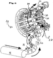
- the ampoules are transported vertically via a transport screw 16 shown only schematically here.
- the vertically vertically transported ampoules 14 are taken from a first obliquely arranged rotating transport star 18, which is formed with a suction mechanism not shown for fixing the ampoules 14 during transport, and at a further inclined even further passed another basically constructed transport star 20. From there, they are handed over to a third similarly constructed vertically oriented transport star 22.
- the transport direction of the transferred ampoules 14 is in the FIG. 2 indicated by the arrows.
- the first transport star 18 is set at an angle ⁇ with respect to the reference plane A, where 0 ° ⁇ ⁇ 45 °.
- the second transport star 20 is set at an angle ⁇ with respect to the reference plane A, wherein 45 ° ⁇ ⁇ 90 °.
- the ampoules 14 are transferred to the inspection carousel 12.
- the products are included in the inspection carousel between sliding lower holders 24 and upper holders 26.
- the lower holders and upper holders 24 and 26 are formed as rotation axis lower parts and rotational axis upper parts which are rotatably held in the inspection carousel 12.
- the ampoules can be rotated about its own axis.
- a belt drive is provided with a belt 28, over which pulleys 30 can be set in rotation.
- the individual ampoules 14 are rotated by means of belt designed as a round belt 28 against the transport direction, which is indicated by the arrow A, in rotation.
- the tangential contact between the belt and the pulleys 30 causes the rotation to start smoothly and slowly so that the slippage of the rotated ampoules 14 remains small.
- the belt 28 is driven separately in a manner not shown here.
- the ampoules 14 While the ampoules 14 are in the inspection carousel 12, these are rotated by 360 ° due to the rotation about their own axis and thus fully inspected.
- the sides of the ampoules 14 are in the inspection carousel from the outside and inside freely accessible.
- an inspection of the entire side wall and the head area (spit) of the respective ampoule 14 can be realized.
- ground electrodes 32 and needle electrodes 34 are arranged accordingly. Due to the circular arrangement, a compact construction of the ground and needle electrodes is possible.
- the ground electrodes are provided inside the inspection carousel 12, while the needle electrodes are arranged on the outside.
- the ampoules 14 are discharged after the high-voltage test by means of the ground electrode 32 and the needle electrode 34 again from the inspection carousel 12.
- three transport stars 36, 38 and 40 are again provided in a similar manner as described above when introducing the ampoules 14, these again being constructed as suction stars, as has already been described above with reference to the transport stars 18, 20 and 22.
- the transport star 36, on which the ampoules 14 are transferred from the inspection carousel, is again perpendicular to the plane A (see FIG. FIG. 3 ).
- the transport stars 38 and 40 again have inclinations, as described with reference to the transport stars 20 and 18.
- the removed from the inspection carousel 12 ampoules 14 can be transferred from the horizontal position to the vertical position. In a vertical position they are then transported by a screw conveyor 42, which in FIG. 1 respectively.
- FIG. 6 only shown schematically, transported away.
- the inspection carousel 12 arranged in the holder 24 and 26 are mounted longitudinally displaceable. They have a so-called Hubkurvenver ein, in which on respective backdrops not shown here corresponding sliding arranged on the lower holders 24 and upper holders 26 slide rollers 44 and 46 and 48 along. Through this Hubkurvenver ein lifting curves for insertion, removal and format change for the products to be inspected or ampoules 14 may be provided.
- the lift curve 1 FIG. 3
- the delivery will be in a range of approx. 2 - 8 mm.
- a delivery of the upper holder 26, that is, the rotational axis upper parts 26 is reached.
- This is used so that the products 14 can be inserted into and removed from the inspection carousel.
- the lifting curves 1 and 2 initially move away from each other linearly to receive the ampoules 14 and during the insertion of the ampoules in the inspection carousel 12 toward each other.
- the lifting curve 2 always performs a fixed movement, namely the so-called opening and closing movement, which requires a longitudinal displacement of about 10 to 20 mm.
- FIG. 3 denotes the third lift curve, which takes place on the interaction of the guide wheels 48 with the guide slot, not shown here.
- This lift curve is for the format and product-dependent height presetting of the upper holder 26, that is, the rotational axis upper parts 26 is provided. As a result, different product heights can be covered.
- the product to be examined can be positioned precisely defined.
- the axis of rotation here corresponds to the product axis, so that by design a largely tolerance-free accurate positioning is achieved.
- the products are also achieved by a drive of the axes of rotation directly and not by pressing the products to a tangentially passed band. This additionally protects the products.
Landscapes
- Chemical & Material Sciences (AREA)
- General Health & Medical Sciences (AREA)
- Life Sciences & Earth Sciences (AREA)
- Health & Medical Sciences (AREA)
- Analytical Chemistry (AREA)
- Biochemistry (AREA)
- Physics & Mathematics (AREA)
- General Physics & Mathematics (AREA)
- Immunology (AREA)
- Pathology (AREA)
- Chemical Kinetics & Catalysis (AREA)
- Electrochemistry (AREA)
- Specific Conveyance Elements (AREA)
- Testing Relating To Insulation (AREA)
Description
- Die Erfindung betrifft eine Vorrichtung zur Prüfung von Erzeugnissen nach dem Oberbegriff des Anspruchs 1.
- Zur Prüfung von Erzeugnissen, wie beispielsweise Ampullen, Flaschen, Zylinderampullen, Vials oder dergleichen werden üblicherweise Inspektionsmaschinen eingesetzt. Die Inspektion erfolgt in der Regel optisch. Bei flüssigen, gefriergetrockneten und opaken Produkten wird in einer Maschine die Partikelinspektion und die Inspektion von kosmetischen Defekten durchgeführt. Bei diesen optischen Inspektionsmethoden bei flüssigen Produkten können Partikel, Schwebeteilchen, Fasern, das Glas und der Füllstand inspiziert werden. Bei gefriergetrockneten Produkten kann das sogenannte "Meltback", ein eingefallener Kuchen, Verfärbungen, Verunreinigungen an Kuchen, nicht gefriergetrocknetes Produkt und der Füllstand überprüft werden. Für Vials können Lage und Farbe der Flip-Off-Kappe, Farbe der Bördelkappe, das Vorhandensein eines gegebenenfalls vorgesehenen Gummistopfens, die Qualität der Bördelung, Dellen und Kratzer in der Bördelkappe, Risse und Kratzer in der Seitenwand und im Boden sowie Verschmutzungen festgestellt werden.
- Bei Ampullen kann beispielsweise mittels der optischen Methode eine Deformierung am Ampullenspieß, ein sogenannter Schwarzbrenner, die Farbringcodierung, Kratzer an der Seitenwand und am Boden sowie Verschmutzungen festgestellt werden. Auch wenn die optischen Inspektionsverfahren eine Vielzahl von verläßlichen Informationen bezüglich der zu prüfenden Erzeugnisse liefern, sind einige Ergebnisse der Inspektion nicht eindeutig. So kann beispielsweise nicht eindeutig festgestellt werden, ob in einer Behälterwand lediglich ein Kratzer oder aber sogar ein Riß vorhanden ist. Beides wird in der optischen Methode als gleicher Fehler festgestellt. Bei dem Erzeugnis mag aber beispielsweise ein Kratzer in der Wandung oder am Boden hinnehmbar sein, während ein Riß zum notwendigen Ausschleusen des Erzeugnisses führen muss.
- Um Kratzer und Risse sicher voneinander unterscheiden zu können, ist es bereits bekannt geworden, das Erzeugnis nach der optischen Prüfung entweder einer Vakuumprüfung oder alternativ einer Hochspannungsprüfung zu unterziehen. Während bei einer Vakuumprüfung die Dichtigkeit des Behältnisses und damit das Vorhandensein einer Risses überprüft wird, wird bei einer Hochspannungsprüfung das Erzeugnis zwischen zwei Elektroden, das heißt zwischen einer Masseelektrode und einer Spitzenelektrode, angeordnet. Schlägt bei Anlegen der Hochspannung der Funke durch, liegt ein Riß vor, so dass das Erzeugnis ausgesondert werden kann. Bei den bislang bekannten Zusatzmodulen zur Hochspannungsprüfung hat sich das Handling der zu prüfenden Erzeugnisse als schwierig erwiesen. Die jeweils zu prüfenden, Erzeugnisse müssen einzeln aufgenommen und in der Prüfposition zwischen den Elektroden gedreht werden. Hierzu waren in der Vergangenheit recht aufwendige und den gesamten Inspektionsprozeß verlangsamende Konstruktionen bekannt.
- Dokument
JP56133654 - Dokument
FR2499952 - Aus der
DE 20 2009 010 781 U ist nun bereits eine Vorrichtung zur Prüfung von Erzeugnissen, insbesondere von Ampullen und Flaschen bekannt, bei der ein drehbar antreibbares Inspektionskarussel vorgesehen ist, in welchem auf Umfang Aufnahmewippen zur rotierbaren Aufnahme der Erzeugnisse angeordnet sind. Die Erzeugnisse werden dabei von den Aufnahmewippen von einer vertikalen Aufnahmeposition in eine zumindest waagerechte Prüfposition verschwenkt. - Dieser vorbekannte Verschwenkmechanismus ist konstruktiv aufwendig und führt zu einem vergleichsweise hohem Wartungsaufwand.
- Aufgabe der Erfindung ist es, eine gattungsgemäße Vorrichtung zur Prüfung von Erzeugnissen derart weiterzubilden, dass die einer optischen Inspektion nachgeschaltete Hochspannungsprüfung der zu prüfenden Erzeugnisse in einfacher und sicherer Weise erfolgen kann, wobei der An- und Abtransport der zu inspizierenden Erzeugnisse vereinfacht werden soll.
- Erfindungsgemäß wird diese Aufgabe durch die Kombination der Merkmale des Anspruchs 1 gelöst. Demnach ist eine Vorrichtung zur Prüfung von Erzeugnissen, insbesondere von Ampullen, Flaschen und dergleichen, mit Mitteln zur Bewegung der zu prüfenden Erzeugnisse und mit Erfassungsmitteln zur Hochspannungsprüfung für die Erzeugnisse geschaffen, wobei diese ein drehbar antreibbares Inspektionskarussel aufweist. Erfindungsgemäß sind die Erzeugnisse mittels mindestens zwei schräg zueinander angeordneter rotierenden Transportsternen von einer vertikalen Aufnahmeposition, in der die Erzeugnisse antransportiert werden, in eine zumindest waagerechte Prüfposition überführbar. Aus dieser waagerechten Prüfposition sind sie wiederum über zwei schräg zueinander angeordnete rotierende Transportsterne in eine vertikale Abgabeposition überführbar.
- Über dieses erfindungsgemäß vorgesehene Inspektionskarussel mit entsprechender Zu- und Abführung können die Erzeugnisse auf ihrem Transportweg, der der optischen Inspektion nachgeschaltet ist, schnell und kontinuierlich übernommen werden und nach der Lageveränderung vom senkrechten in den waagerechten Zustand durch die schräg zueinander angeordneten rotierenden Transportsterne in die horizontale Prüfposition im Inspektionskarussel übergeben werden. In dieser horizontalen Prüfposition werden sie überprüft, bevor sie wieder in eine vertikale Abgabeposition verschwenkt werden, um dann, je nach Prüfergebnis entweder als defektes Erzeugnis ausgeschleust zu werden oder als sogenanntes Gutprodukt nach bestandener Hochspannungsprüfung ausgeschleust und anschließend abgepackt zu werden.
- Bevorzugte Ausgestaltungen der Erfindung ergeben sich aus den sich an den Hauptanspruch anschließenden Unteransprüchen.
- Demnach kann dem Inspektionskarussel ein bezogen auf die Zuführebene der Erzeugnisse senkrecht angeordneter Transportstern zugeordnet sein.
- Besonders vorteilhaft kann ein erster Transportstern die kontinuierlich angeförderten vertikal stehenden Erzeugnisse aufnehmen und aufgrund seiner Schrägstellung schräg an den benachbart angeordneten Transportstern übergeben, der diese Erzeugnisse durch seine noch weiter geneigte Schrägstellung noch weiter kippt und schließlich an den senkrecht zur Zuführebene angeordneten weiteren Transportstern übergeben kann, der die Erzeugnisse nun in waagerechter Position an das Inspektionskarussel übergibt. Die Erzeugnisse können nach Durchlaufen des Inspektionskarussels an einen ebenfalls senkrecht zur Zuführebene angeordneten Transportstern übergeben werden, von dem die Erzeugnisse dann wiederum durch weiteren Transport über zwei schräg angeordnete Transportsterne vertikal aufgerichtet abgegeben werden können. Durch die jeweils schräg zueinander angeordneten Transportstern kann eine kontinuierliche Übernahme und Weitergabe der Erzeugnisse in sehr einfacher, kompakter und wenig störanfälliger Bauweise erzielt werden.
- Die Erzeugnisse können dann im Inspektionskarussel zwischen verschiebbaren unteren und oberen Haltern aufnehmbar sein. Dabei können die Halter vorteilhaft als Rotationsachsenunterteile und Rotationsachsenoberteile ausgebildet sein, zwischen denen die Erzeugnisse einkoppelbar, das heißt beispielsweise einklemmbar, sind.
- Die Erzeugnisse sind üblicherweise im eingekoppelten Zustand zwischen den Rotationsachsenunterteilen und den Rotationsachsenoberteilen um ihre eigene Achse rotierbar.
- Die Elektroden zur Hochspannungsprüfung und vorzugsweise jeweils die zugeordnete Masse- und Nadelelektroden, sind im Inspektionskarussel angeordnet, so dass die Erzeugnisse während des Transports durch den Inspektionsstand an den jeweiligen Elektroden vorbeigeführt werden.
- Die jeweiligen Halter, das heißt die Rotationsachsenunterteile und Rotationsachsenoberteile sind vorteilhaft jeweils über eine Hubkurvenverstellung verschiebbar im Inspektionskarussel gelagert, dabei kann eine erste Hubkurvenverstellung eine Zustellung der Rotationsachsenunterteile und eine zweite Hubkurvenverstellung eine Zustellung der Rotationsachsenoberteile bewirken.
- Eine dritte Hubkurvenverstellung kann vorgesehen sein, um eine von der Erzeugnisgröße abhängige Voreinstellung der Rotationsachenoberteile zu ermöglichen. Hierdurch können bei Bedarf verschieden große Erzeugnisse im Inspektionskarussel aufgenommen werden.
- Besonders vorteilhaft sind die Transportsterne als Saugsterne ausgebildet. Hierdurch können die entsprechenden Erzeugnisse, also beispielsweise die Ampullen oder Flaschen, sicher im Transportstern während ihres Transports gehalten werden, in sehr sicherer Weise aufgenommen und auch wieder abgegeben werden.
- Zur Einleitung der Eigenrotation der im Inspektionsstern geprüften Erzeugnisse kann vorzugsweise ein Riemenantrieb vorgesehen sein.
- Vorteilhaft können die zu inspizierenden Erzeugnisse kontinuierlich über eine Transportschnecke der Prüfvorrichtung zugeführt werden. In gleicher Weise können die aus der Prüfvorrichtung wieder ausgeschleusten Erzeugnisse kontinuierlich mit einer entsprechenden zweiten Transportschnecke abtransportiert werden.
- Weitere Merkmale, Einzelheiten und Vorteile der Erfindung werden anhand eines in der Zeichnung dargestellten Ausführungsbeispiels näher erläutert. Es zeigen:
- Figur 1:
- eine perspektivische Ansicht einer Ausführungsform der erfindungsgemäßen Vorrichtung in vereinfachter Darstellung,
- Figur 2:
- eine Detaildarstellung der
Figur 1 , die teilweise geschnitten ist, - Figur 3:
- eine Seitenansicht der Vorrichtung gemäß
Figur 1 , - Figur 4:
- eine weitere perspektivische Darstellung der
Figur 1 aus einem Blickwinkel, - Figur 5:
- eine Seitenansicht des Inspektionskarussels mit den Elektroden zur Spannungsprüfung und
- Figur 6:
- eine perspektivische Ansicht der Vorrichtung nach
Figur 1 von der Rückseite. - In
Figur 1 ist eine Vorrichtung 10 zur Prüfung von Erzeugnissen, insbesondere von Ampullen, Zylinderampullen, Flaschen, Vials oder dergleichen gezeigt. Kernstück der Vorrichtung ist ein Inspektionskarussel 12, in welches die zu prüfenden Erzeugnisse 14 einsetzbar sind. Im hier dargestellten Ausführungsbeispiel sind die Erzeugnisse 14 Ampullen. Wie aus derFigur 1 ersichtlich, werden die Ampullen über eine hier nur schematisch dargestellte Transportschnecke 16 senkrecht stehend antransportiert. - Die senkrecht vertikal antransportierten Ampullen 14 werden von einem ersten schräg angeordneten rotierenden Transportstern 18, der mit einem nicht näher dargestellten Saugmechanismus zur Festlegung der Ampullen 14 während des Transports ausgebildet ist, übernommen und an einen weiteren noch weiter schräg stehenden weiteren grundsätzlich gleich aufgebauten Transportstern 20 übergeben. Von dort aus werden sie an einen dritten ebenfalls gleich aufgebauten senkrecht ausgerichteten Transportstern 22 übergeben. Die Transportrichtung der übergebenen Ampullen 14 wird in der
Figur 2 durch die Pfeile angegeben. - Während des Transports über die Transportsterne 18 und 20 werden die vertikal antransportierten Ampullen 14 in ein horizontale Abgabeposition überführt. Die Schrägstellung der Transportsterne 18, 20 zur Bezugsebene A ergibt sich aus
Fig. 3 . Der erste Transportstern 18 ist um einen Winkel α gegenüber der Bezugsebene A angestellt, wobei 0° < α < 45° ist. Der zweite Transportstern 20 ist um einen Winkel β gegenüber der Bezugsebene A angestellt, wobei 45° < β <90° ist. - Vom dritten Transportstern 22 aus werden die Ampullen 14 an das Inspektionskarussel 12 übergeben. Hierzu werden die Erzeugnisse im Inspektionskarussel zwischen verschiebbaren unteren Haltern 24 und oberen Haltern 26 aufgenommen. Die unteren Halter und oberen Halter 24 und 26 sind als Rotationsachsenunterteile und Rotationsachsenoberteile ausgebildet, die drehbar im Inspektionskarussel 12 gehalten sind. Über diese drehbaren Halter 24 und 26 können die Ampullen um ihre eigene Achse gedreht werden. Hierzu ist ein Riemenantrieb mit einem Riemen 28 vorgesehen, über den Riemenscheiben 30 in Rotation versetzbar sind. Wie den Pfeilen in
Figur 6 zu entnehmen ist, werden die einzelnen Ampullen 14 mit Hilfe des als Rundriemen ausgebildeten Riemens 28 gegen die Transportrichtung, die mit dem Pfeil A angegeben ist, in Rotation versetzt. - Durch den tangentialen Kontakt zwischen dem Riemen und den Riemenscheiben 30 wird erreicht, dass die Rotation sanft und langsam anläuft, so dass der Schlupf der in Rotation versetzten Ampullen 14 klein bleibt. Der Riemen 28 wird in hier nicht näher dargestellter Weise separat angetrieben.
- Während sich die Ampullen 14 im Inspektionskarussel 12 befinden, werden diese aufgrund der Rotation um ihre eigene Achse um 360° gedreht und somit vollständig inspiziert. Die Seiten der Ampullen 14 sind im Inspektionskarussel von außen und innen frei zugänglich. Somit kann im Inspektionskarussel 12 eine Inspektion der kompletten Seitenwand und des Kopfbereichs (Spieß) der jeweiligen Ampulle 14 realisiert werden.
- In
Figur 5 ist gezeigt, wie hier entsprechend zwei Masseelektroden 32 und Nadelelektroden 34 angeordnet sind. Aufgrund der Kreisanordnung ist ein kompakter Aufbau der Masse- und Nadelelektroden möglich. Im hier dargestellten Ausführungsbeispiel sind die Masseelektroden innen im Inspektionskarussel 12 vorgesehen, während die Nadelelektroden außen angeordnet sind. - Wie insbesondere den
Figuren 1 ,4 und6 zu entnehmen ist, werden die Ampullen 14 nach der Hochspannungsprüfung mittels der Masseelektrode 32 bzw. der Nadelelektrode 34 wieder aus dem Inspektionskarussel 12 ausgeschleust. Hierzu sind in ähnlicher Weise wie zuvor beim Einschleusen der Ampullen 14 beschrieben, wieder drei Transportsterne 36, 38 und 40 vorgesehen, wobei diese wieder als Saugsterne aufgebaut sind, wie es bereits anhand der Transportsterne 18, 20 und 22 zuvor beschrieben wurde. Der Transportstern 36, an dem die Ampullen 14 aus dem Inspektionskarussel übergeben werden, ist wiederum senkrecht zur Ebene A (vgl.Figur 3 ) ausgerichtet. Die Transportsterne 38 und 40 weisen wieder Schrägstellungen auf, wie sie anhand der Transportsterne 20 und 18 beschrieben wurden. Somit können die vom Inspektionskarussel 12 abtransportierten Ampullen 14 von der waagerechten Position in die vertikale Position übertragen werden. In vertikaler Position werden sie dann von einer Transportschnecke 42, die inFigur 1 bzw.Figur 6 nur schematisch dargestellt ist, abtransportiert. - Die im Inspektionskarussel 12 angeordneten Halter 24 und 26 sind längsverschieblich gelagert. Sie weisen eine sogenannte Hubkurvenverstellung auf, bei der über entsprechende hier nicht näher dargestellte Kulissen entsprechende an den unteren Haltern 24 bzw. oberen Haltern 26 angeordnete Kulissenrollen 44 bzw. 46 und 48 entlang gleiten. Über diese Hubkurvenverstellung können Hubkurven für das Einsetzen, das Herausnehmen und den Formatwechsel für die zu inspizierenden Erzeugnisse bzw. Ampullen 14 vorgesehen werden. Die Hubkurve 1 (
Figur 3 ) ermöglicht dabei eine Zustellung der unteren Halter 24, das heißt der Rotationsachsenunterteile 24, um eventuell vorhandene Fehlstellungen, die durch die Übergabe der Ampullen 14 mittels der Transportsterne 18 bis 22 entstanden sind, auszugleichen. Die Zustellung wird hier in einem Bereich von ca. 2 - 8 mm liegen. - Über die Hubkurve 2, das heißt die entsprechenden Kulissenräder 46 und die zugehörige hier nicht näher dargestellte Kulisse wird eine Zustellung der oberen Halter 26, das heißt der Rotationsachsenoberteile 26 erreicht. Diese wird dazu verwendet, dass die Erzeugnisse 14 ins Inspektionskarussel eingesetzt und aus diesem wieder herausgenommen werden können. Hierzu bewegen sich die Hubkurven 1 und 2 zunächst linear voneinander weg, um die Ampullen 14 aufzunehmen und während des Einsetzens der Ampullen in das Inspektionskarussel 12 aufeinander zu. Die Hubkurve 2 vollzieht hierbei immer eine feste Bewegung, nämlich die sogenannte Öffnungs- und Schließbewegung, die eine Längsverschiebung von ca. 10 bis 20 mm bedingt.
- Schließlich ist mit 3 (
Figur 3 ) die dritte Hubkurve bezeichnet, die auf das Zusammenwirken der Kulissenräder 48 mit der hier nicht näher dargestellten Kulissenführung erfolgt. Diese Hubkurve ist für die format- und produktabhängige Höhenvoreinstellung der oberen Halter 26, das heißt der Rotationsachsenoberteile 26 vorgesehen. Hierdurch können verschiedene Produkthöhen abgedeckt werden. - Mit der vorgenannten Prüfvorrichtung können somit undichte Erzeugnisse 12 mittels Hochspannung auf kleinstem Raum mit einem neuen mechanischen Konzept auf Undichtigkeit überprüft werden. Aufgrund der exakten Aufnahme der Ampullen im Inspektionskarussel durch die unteren und oberen Halter kann das jeweils zu untersuchende Erzeugnis genau definiert positioniert werden. Die Rotationsachse entspricht hier der Produktachse, so dass konstruktionsbedingt eine weitgehend toleranzfreie genaue Positionierung erreicht wird. Erfindungsgemäß werden die Produkte auch durch einen Antrieb der Rotationsachsen unmittelbar und nicht über Andrücken der Produkte an ein tangential vorbeigeführtes Band erzielt. Hierdurch werden die Erzeugnisse zusätzlich geschont.
Claims (12)
- Vorrichtung zur Prüfung von Erzeugnissen (14), insbesondere von Ampullen, Flaschen und dergleichen, mit Mitteln (12) zur Bewegung der zu prüfenden Erzeugnisse (14) und mit Erfassungsmitteln zur Hochspannungsprüfung für die Erzeugnisse (14), wobei sie ein drehbar antreibbares Inspektionskarussel (12) und mindestens zwei Transportsterne (18,20;38,40) aufweist,
dadurch gekennzeichnet, dass die mindestens zwei Transportsterne (18,20;38,40) als Saugsterne ausgebildet sind und die mindestens zwei Transportsterne (18,20;38,40) schräg zueinander angeordnet sind, und dass die Erzeugnisse (14) mittels mindestens zwei schräg zueinander angeordneten, rotierenden, als Saugsterne ausgebiledeten Transportsternen (18, 20; 38, 40) von einer vertikalen Aufnahmeposition in eine zumindest waagerechte Prüfposition und umgekehrt überführbar sind. - Vorrichtung nach Anspruch 1, dadurch gekennzeichnet, dass zur Einleitung der Eigenrotation der im Inspektionsstern geprüften Erzeugnisse (14) ein Riemenantrieb vorgesehen ist.
- Vorrichtung nach Anspruch 1 oder 2, dadurch gekennzeichnet, dass dem Inspektionskarussel ein bezogen auf die Zuführebene der Erzeugnisse (14) senkrecht angeordneter Transportstern (22) zugeordnet ist.
- Vorrichtung nach einem der vorhergehenden Ansprüche, dadurch gekennzeichnet, dass der erste Transportstern (18) derart angeordnet ist die vertikal stehenden Erzeugnisse (14) aufzunehmen und aufgrund seiner Schrägstellung schräg an den benachbart angeordneten Transportstern (20) zu übergeben, der angeordnet ist diese Erzeugnisse (14) durch seine noch weiter geneigte Schrägstellung noch weiter zu kippen und schließlich an den senkrecht zur Zuführebene angeordneten Transportstern (22) zu übergeben, der angeordnet ist die Erzeugnisse (14) nun in waagerechter Position an das Inspektionskarussel (12) zu übergeben und dass die Vorrichtung ausgebildet ist die Erzeugnisse (14) nach Durchlaufen des Inspektionskarussels (12) an einen ebenfalls senkrecht zur Zuführebene angeordneten dritten Transportstern (36) zu übergeben, wobei der dritte Transportstern (36) derart angeordnet ist die Erzeugnisse (14) wiederum durch weiteren Transport über zwei schräg angeordnete vierte und fünfte Transportsterne (38, 40) vertikal aufgerichtet abzugeben.
- Vorrichtung nach einem der vorhergehenden Ansprüche, dadurch gekennzeichnet, dass das Inspektionskarussel verschiebbare untere und obere Halter (24,26) umfasst und die Erzeugnisse (14) im Inspektionskarussel zwischen den verschiebbaren unteren und oberen Haltern (24, 26) aufnehmbar sind.
- Vorrichtung nach Anspruch 5, dadurch gekennzeichnet, dass die jeweiligen Halter (24, 26) als Rotationsachsenunterteile und Rotationsachsenoberteile ausgebildet sind, zwischen denen die Erzeugnisse (14) einkoppelbar sind.
- Vorrichtung nach Anspruch 6, dadurch gekennzeichnet, dass die Erzeugnisse (14) im eingekoppelten Zustand zwischen den Rotationsachsenunterteilen und den Rotationsachsenoberteilen um ihre eigene Achse rotierbar sind.
- Vorrichtung nach einem der vorhergehenden Ansprüche, dadurch gekennzeichnet, dass im Inspektionskarussel (12) Elektroden, vorzugsweise jeweils zugeordnete Masse- und Nadelelektroden (32, 34), angeordnet sind, über die die Erzeugnisse (14) prüfbar sind.
- Vorrichtung nach einem der vorhergehenden Ansprüche 5-8, dadurch gekennzeichnet, dass die jeweiligen Halter (24, 26) über eine Hubkurvenverstellung verschiebbar im Inspektionskarussel (12) gelagert sind.
- Vorrichtung nach Anspruch 9, dadurch gekennzeichnet, dass eine erste Hubkurvenverstellung eine Zustellung der Rotationsachsenunterteile und eine zweite Hubkurvenverstellung eine Zustellung der Rotationsachsenoberteile bewirkt.
- Vorrichtung nach Anspruch 10, dadurch gekennzeichnet, dass eine dritte Hubkurbenverstellung vorhanden ist, die eine von der Erzeugnisgröße abhängige Voreinstellung der Rotationsachenoberteile ermöglicht.
- Vorrichtung nach einem der vorhergehenden Ansprüche, dadurch gekennzeichnet, dass eine Transportschnecke (16) vorgesehen ist, über die die Erzeugnisse (14) in vertikaler Aufnahmeposition antransportiert und eine Transportschnecke (42) vorgesehen ist, über die die Erzeugnisse (14) in vertikaler Abgabeposition abtransportiert werden.
Applications Claiming Priority (1)
| Application Number | Priority Date | Filing Date | Title |
|---|---|---|---|
| DE202012009944.2U DE202012009944U1 (de) | 2012-10-12 | 2012-10-12 | Vorrichtung zur Prüfung von Erzeugnissen |
Publications (3)
| Publication Number | Publication Date |
|---|---|
| EP2720036A2 EP2720036A2 (de) | 2014-04-16 |
| EP2720036A3 EP2720036A3 (de) | 2015-01-07 |
| EP2720036B1 true EP2720036B1 (de) | 2016-12-28 |
Family
ID=49236984
Family Applications (1)
| Application Number | Title | Priority Date | Filing Date |
|---|---|---|---|
| EP13004521.4A Active EP2720036B1 (de) | 2012-10-12 | 2013-09-16 | Vorrichtung zur Prüfung von Erzeugnissen |
Country Status (3)
| Country | Link |
|---|---|
| EP (1) | EP2720036B1 (de) |
| DE (1) | DE202012009944U1 (de) |
| DK (1) | DK2720036T3 (de) |
Cited By (1)
| Publication number | Priority date | Publication date | Assignee | Title |
|---|---|---|---|---|
| US12170849B2 (en) | 2022-02-04 | 2024-12-17 | Applied Materials, Inc. | Pulsed illumination for fluid inspection |
Families Citing this family (3)
| Publication number | Priority date | Publication date | Assignee | Title |
|---|---|---|---|---|
| WO2016210420A1 (en) | 2015-06-26 | 2016-12-29 | Abbott Laboratories | Reaction vessel exchanger device for a diagnostic analyzer |
| ES1244195Y1 (es) * | 2019-11-28 | 2021-04-20 | Posimat Sa | Maquina para el posicionamiento automatico de objetos |
| DE102022118950A1 (de) * | 2022-07-28 | 2024-02-08 | Thyssenkrupp Ag | Vorrichtung zur Bearbeitung und/oder Prüfung einer Vielzahl von Batteriezellen und Verfahren zur Bearbeitung und/oder Prüfung einer Vielzahl von Batteriezellen |
Family Cites Families (7)
| Publication number | Priority date | Publication date | Assignee | Title |
|---|---|---|---|---|
| JPS56133654A (en) * | 1980-03-24 | 1981-10-19 | Densoku Kogyo Kk | Detecting machine for pinhole of airtight ampul |
| FR2499952A1 (fr) * | 1981-02-17 | 1982-08-20 | Cugnart Pascal | Dispositif rotatif d'inclinaison ou de relevage |
| EP0324046A1 (de) * | 1988-01-15 | 1989-07-19 | S O "Pharmachim" | Vorrichtung zum automatisierten Markieren von Ampullen |
| DE4022733C1 (en) * | 1989-12-19 | 1991-05-08 | Elpatronic Ag, Zug, Ch | Three=dimensional cavity inspection appts. - uses matrix or line camera to receive reflected light via gp. of four mirrors and deflecting mirror |
| FR2660917B1 (fr) * | 1990-04-11 | 1992-11-20 | Perrier Rene | Pince de prehension et machine de traitement d'objets, notamment de bouteilles, ainsi equipee. |
| DE202009010781U1 (de) | 2009-06-04 | 2010-10-21 | Seidenader Maschinenbau Gmbh | Vorrichtung zur Prüfung von Erzeugnissen |
| IT1403403B1 (it) * | 2010-12-03 | 2013-10-17 | Fameccanica Data Spa | Apparecchiatura e procedimento per l'alimentazione di bottiglie ad una stazione di riempimento |
-
2012
- 2012-10-12 DE DE202012009944.2U patent/DE202012009944U1/de not_active Expired - Lifetime
-
2013
- 2013-09-16 DK DK13004521.4T patent/DK2720036T3/en active
- 2013-09-16 EP EP13004521.4A patent/EP2720036B1/de active Active
Non-Patent Citations (1)
| Title |
|---|
| None * |
Cited By (1)
| Publication number | Priority date | Publication date | Assignee | Title |
|---|---|---|---|---|
| US12170849B2 (en) | 2022-02-04 | 2024-12-17 | Applied Materials, Inc. | Pulsed illumination for fluid inspection |
Also Published As
| Publication number | Publication date |
|---|---|
| EP2720036A2 (de) | 2014-04-16 |
| DK2720036T3 (en) | 2017-03-13 |
| EP2720036A3 (de) | 2015-01-07 |
| DE202012009944U1 (de) | 2014-01-20 |
Similar Documents
| Publication | Publication Date | Title |
|---|---|---|
| DE4214958C2 (de) | Kontinuierlich arbeitende Inspektionsmaschine für Gefäße | |
| EP1570256B1 (de) | Vorrichtung zum inspizieren von gefüllten und verschlossenen gefässen | |
| DE3722422C2 (de) | ||
| DE3621976C2 (de) | ||
| EP2369328B1 (de) | Vorrichtung und verfahren zum untersuchen von befüllten behältnissen auf fremdkörper | |
| DE102010018823B4 (de) | Schwebstofferkennung in mit Flüssigkeit befüllten Behältnissen | |
| EP2720036B1 (de) | Vorrichtung zur Prüfung von Erzeugnissen | |
| DE102005057872B4 (de) | Inspektionsmaschine | |
| EP2276671B1 (de) | Vorrichtung sowie verfahren zur inspektion von flaschen oder dergleichen behältern | |
| DE2352646B2 (de) | Ampullenfuell- und -verschliessmaschine | |
| DE3033531A1 (de) | Vorrichtung zur pruefung von glasbehaeltern | |
| DE2308910B2 (de) | Vorrichtung zum selbsttätigen Prüfen von Hohlgläsern, zum Beispiel Flaschen mit engem Hals, auf Schadstellen und Verunreinigungen durch Fremdkörper, Laugen- und Waschwasserreste | |
| DE1473688C3 (de) | Verfahren zur zerstörungsfreien Prüfung von Glaserzeugnissen und Vorrichtung zur Durchführung des Verfahrens | |
| WO2021004819A1 (de) | Verfahren und vorrichtung zum prüfen von vorformlingen | |
| EP1371944A2 (de) | Vorrichtung zum Prüfen einer Behältermündung auf das Vorhandensein einer Neigung | |
| DE1914929A1 (de) | Probenwechsler bei einem Roentgenspektralanalysengeraet | |
| DE202009010781U1 (de) | Vorrichtung zur Prüfung von Erzeugnissen | |
| DE102019101812A1 (de) | Vorrichtung und Verfahren zum Inspizieren von mehreren Arten von Behältern | |
| DE1573687C3 (de) | Verfahren zum Prüfen gefüllter Ampullen auf ihre und ihres Inhalts einwandfreie Beschaffenheit und Vorrichtung zu seiner Durchführung | |
| DE20208174U1 (de) | Vorrichtung zur Handhabung von Gegenständen und zur Prüfung derselben mit einer Prüfeinrichtung auf Materialfehler | |
| DE102006048327A1 (de) | Verfahren und Vorrichtung zur optischen Erfassung von Fremdkörpern in mit Flüssigkeit gefüllten Flaschen | |
| DE2913541A1 (de) | Vorrichtung zur optischen pruefung und kontrolle von flaschen und ampullen | |
| EP0672902A1 (de) | Verfahren und Vorrichtungen zur Feststellung von Verunreinigungen in Flüssigkeiten | |
| EP0632888B1 (de) | Verfahren zum überprüfen der oberfläche einer mehrzahl kleiner gegenstände, und vorrichtung zur durchführung des verfahrens | |
| DE2310837C3 (de) | Prüfvorrichtung zum Ermitteln von Löchern in Wänden von Behältern mit offenem Ende |
Legal Events
| Date | Code | Title | Description |
|---|---|---|---|
| PUAI | Public reference made under article 153(3) epc to a published international application that has entered the european phase |
Free format text: ORIGINAL CODE: 0009012 |
|
| AK | Designated contracting states |
Kind code of ref document: A2 Designated state(s): AL AT BE BG CH CY CZ DE DK EE ES FI FR GB GR HR HU IE IS IT LI LT LU LV MC MK MT NL NO PL PT RO RS SE SI SK SM TR |
|
| AX | Request for extension of the european patent |
Extension state: BA ME |
|
| PUAL | Search report despatched |
Free format text: ORIGINAL CODE: 0009013 |
|
| AK | Designated contracting states |
Kind code of ref document: A3 Designated state(s): AL AT BE BG CH CY CZ DE DK EE ES FI FR GB GR HR HU IE IS IT LI LT LU LV MC MK MT NL NO PL PT RO RS SE SI SK SM TR |
|
| AX | Request for extension of the european patent |
Extension state: BA ME |
|
| RIC1 | Information provided on ipc code assigned before grant |
Ipc: B65G 29/02 20060101ALI20141201BHEP Ipc: G01N 35/04 20060101ALI20141201BHEP Ipc: G01N 27/92 20060101AFI20141201BHEP |
|
| 17P | Request for examination filed |
Effective date: 20150316 |
|
| GRAP | Despatch of communication of intention to grant a patent |
Free format text: ORIGINAL CODE: EPIDOSNIGR1 |
|
| INTG | Intention to grant announced |
Effective date: 20160811 |
|
| GRAS | Grant fee paid |
Free format text: ORIGINAL CODE: EPIDOSNIGR3 |
|
| GRAA | (expected) grant |
Free format text: ORIGINAL CODE: 0009210 |
|
| AK | Designated contracting states |
Kind code of ref document: B1 Designated state(s): AL AT BE BG CH CY CZ DE DK EE ES FI FR GB GR HR HU IE IS IT LI LT LU LV MC MK MT NL NO PL PT RO RS SE SI SK SM TR |
|
| REG | Reference to a national code |
Ref country code: GB Ref legal event code: FG4D Free format text: NOT ENGLISH |
|
| REG | Reference to a national code |
Ref country code: CH Ref legal event code: EP Ref country code: CH Ref legal event code: NV Representative=s name: KELLER AND PARTNER PATENTANWAELTE AG, CH |
|
| REG | Reference to a national code |
Ref country code: AT Ref legal event code: REF Ref document number: 857738 Country of ref document: AT Kind code of ref document: T Effective date: 20170115 |
|
| REG | Reference to a national code |
Ref country code: IE Ref legal event code: FG4D Free format text: LANGUAGE OF EP DOCUMENT: GERMAN |
|
| REG | Reference to a national code |
Ref country code: DE Ref legal event code: R096 Ref document number: 502013005872 Country of ref document: DE |
|
| PG25 | Lapsed in a contracting state [announced via postgrant information from national office to epo] |
Ref country code: LV Free format text: LAPSE BECAUSE OF FAILURE TO SUBMIT A TRANSLATION OF THE DESCRIPTION OR TO PAY THE FEE WITHIN THE PRESCRIBED TIME-LIMIT Effective date: 20161228 |
|
| REG | Reference to a national code |
Ref country code: DK Ref legal event code: T3 Effective date: 20170309 |
|
| REG | Reference to a national code |
Ref country code: LT Ref legal event code: MG4D |
|
| PG25 | Lapsed in a contracting state [announced via postgrant information from national office to epo] |
Ref country code: GR Free format text: LAPSE BECAUSE OF FAILURE TO SUBMIT A TRANSLATION OF THE DESCRIPTION OR TO PAY THE FEE WITHIN THE PRESCRIBED TIME-LIMIT Effective date: 20170329 Ref country code: NO Free format text: LAPSE BECAUSE OF FAILURE TO SUBMIT A TRANSLATION OF THE DESCRIPTION OR TO PAY THE FEE WITHIN THE PRESCRIBED TIME-LIMIT Effective date: 20170328 Ref country code: SE Free format text: LAPSE BECAUSE OF FAILURE TO SUBMIT A TRANSLATION OF THE DESCRIPTION OR TO PAY THE FEE WITHIN THE PRESCRIBED TIME-LIMIT Effective date: 20161228 Ref country code: LT Free format text: LAPSE BECAUSE OF FAILURE TO SUBMIT A TRANSLATION OF THE DESCRIPTION OR TO PAY THE FEE WITHIN THE PRESCRIBED TIME-LIMIT Effective date: 20161228 |
|
| REG | Reference to a national code |
Ref country code: NL Ref legal event code: MP Effective date: 20161228 |
|
| PG25 | Lapsed in a contracting state [announced via postgrant information from national office to epo] |
Ref country code: RS Free format text: LAPSE BECAUSE OF FAILURE TO SUBMIT A TRANSLATION OF THE DESCRIPTION OR TO PAY THE FEE WITHIN THE PRESCRIBED TIME-LIMIT Effective date: 20161228 Ref country code: HR Free format text: LAPSE BECAUSE OF FAILURE TO SUBMIT A TRANSLATION OF THE DESCRIPTION OR TO PAY THE FEE WITHIN THE PRESCRIBED TIME-LIMIT Effective date: 20161228 Ref country code: FI Free format text: LAPSE BECAUSE OF FAILURE TO SUBMIT A TRANSLATION OF THE DESCRIPTION OR TO PAY THE FEE WITHIN THE PRESCRIBED TIME-LIMIT Effective date: 20161228 |
|
| PG25 | Lapsed in a contracting state [announced via postgrant information from national office to epo] |
Ref country code: NL Free format text: LAPSE BECAUSE OF FAILURE TO SUBMIT A TRANSLATION OF THE DESCRIPTION OR TO PAY THE FEE WITHIN THE PRESCRIBED TIME-LIMIT Effective date: 20161228 |
|
| PG25 | Lapsed in a contracting state [announced via postgrant information from national office to epo] |
Ref country code: RO Free format text: LAPSE BECAUSE OF FAILURE TO SUBMIT A TRANSLATION OF THE DESCRIPTION OR TO PAY THE FEE WITHIN THE PRESCRIBED TIME-LIMIT Effective date: 20161228 Ref country code: SK Free format text: LAPSE BECAUSE OF FAILURE TO SUBMIT A TRANSLATION OF THE DESCRIPTION OR TO PAY THE FEE WITHIN THE PRESCRIBED TIME-LIMIT Effective date: 20161228 Ref country code: IS Free format text: LAPSE BECAUSE OF FAILURE TO SUBMIT A TRANSLATION OF THE DESCRIPTION OR TO PAY THE FEE WITHIN THE PRESCRIBED TIME-LIMIT Effective date: 20170428 Ref country code: CZ Free format text: LAPSE BECAUSE OF FAILURE TO SUBMIT A TRANSLATION OF THE DESCRIPTION OR TO PAY THE FEE WITHIN THE PRESCRIBED TIME-LIMIT Effective date: 20161228 Ref country code: EE Free format text: LAPSE BECAUSE OF FAILURE TO SUBMIT A TRANSLATION OF THE DESCRIPTION OR TO PAY THE FEE WITHIN THE PRESCRIBED TIME-LIMIT Effective date: 20161228 |
|
| PG25 | Lapsed in a contracting state [announced via postgrant information from national office to epo] |
Ref country code: SM Free format text: LAPSE BECAUSE OF FAILURE TO SUBMIT A TRANSLATION OF THE DESCRIPTION OR TO PAY THE FEE WITHIN THE PRESCRIBED TIME-LIMIT Effective date: 20161228 Ref country code: ES Free format text: LAPSE BECAUSE OF FAILURE TO SUBMIT A TRANSLATION OF THE DESCRIPTION OR TO PAY THE FEE WITHIN THE PRESCRIBED TIME-LIMIT Effective date: 20161228 Ref country code: PT Free format text: LAPSE BECAUSE OF FAILURE TO SUBMIT A TRANSLATION OF THE DESCRIPTION OR TO PAY THE FEE WITHIN THE PRESCRIBED TIME-LIMIT Effective date: 20170428 Ref country code: BG Free format text: LAPSE BECAUSE OF FAILURE TO SUBMIT A TRANSLATION OF THE DESCRIPTION OR TO PAY THE FEE WITHIN THE PRESCRIBED TIME-LIMIT Effective date: 20170328 Ref country code: PL Free format text: LAPSE BECAUSE OF FAILURE TO SUBMIT A TRANSLATION OF THE DESCRIPTION OR TO PAY THE FEE WITHIN THE PRESCRIBED TIME-LIMIT Effective date: 20161228 |
|
| REG | Reference to a national code |
Ref country code: DE Ref legal event code: R097 Ref document number: 502013005872 Country of ref document: DE |
|
| PLBE | No opposition filed within time limit |
Free format text: ORIGINAL CODE: 0009261 |
|
| STAA | Information on the status of an ep patent application or granted ep patent |
Free format text: STATUS: NO OPPOSITION FILED WITHIN TIME LIMIT |
|
| 26N | No opposition filed |
Effective date: 20170929 |
|
| PG25 | Lapsed in a contracting state [announced via postgrant information from national office to epo] |
Ref country code: SI Free format text: LAPSE BECAUSE OF FAILURE TO SUBMIT A TRANSLATION OF THE DESCRIPTION OR TO PAY THE FEE WITHIN THE PRESCRIBED TIME-LIMIT Effective date: 20161228 |
|
| GBPC | Gb: european patent ceased through non-payment of renewal fee |
Effective date: 20170916 |
|
| PG25 | Lapsed in a contracting state [announced via postgrant information from national office to epo] |
Ref country code: MC Free format text: LAPSE BECAUSE OF FAILURE TO SUBMIT A TRANSLATION OF THE DESCRIPTION OR TO PAY THE FEE WITHIN THE PRESCRIBED TIME-LIMIT Effective date: 20161228 |
|
| REG | Reference to a national code |
Ref country code: IE Ref legal event code: MM4A |
|
| REG | Reference to a national code |
Ref country code: BE Ref legal event code: MM Effective date: 20170930 |
|
| PG25 | Lapsed in a contracting state [announced via postgrant information from national office to epo] |
Ref country code: LU Free format text: LAPSE BECAUSE OF NON-PAYMENT OF DUE FEES Effective date: 20170916 |
|
| REG | Reference to a national code |
Ref country code: FR Ref legal event code: ST Effective date: 20180531 |
|
| PG25 | Lapsed in a contracting state [announced via postgrant information from national office to epo] |
Ref country code: GB Free format text: LAPSE BECAUSE OF NON-PAYMENT OF DUE FEES Effective date: 20170916 Ref country code: IE Free format text: LAPSE BECAUSE OF NON-PAYMENT OF DUE FEES Effective date: 20170916 |
|
| PG25 | Lapsed in a contracting state [announced via postgrant information from national office to epo] |
Ref country code: BE Free format text: LAPSE BECAUSE OF NON-PAYMENT OF DUE FEES Effective date: 20170930 Ref country code: FR Free format text: LAPSE BECAUSE OF NON-PAYMENT OF DUE FEES Effective date: 20171002 |
|
| PG25 | Lapsed in a contracting state [announced via postgrant information from national office to epo] |
Ref country code: MT Free format text: LAPSE BECAUSE OF FAILURE TO SUBMIT A TRANSLATION OF THE DESCRIPTION OR TO PAY THE FEE WITHIN THE PRESCRIBED TIME-LIMIT Effective date: 20161228 |
|
| PG25 | Lapsed in a contracting state [announced via postgrant information from national office to epo] |
Ref country code: HU Free format text: LAPSE BECAUSE OF FAILURE TO SUBMIT A TRANSLATION OF THE DESCRIPTION OR TO PAY THE FEE WITHIN THE PRESCRIBED TIME-LIMIT; INVALID AB INITIO Effective date: 20130916 |
|
| PG25 | Lapsed in a contracting state [announced via postgrant information from national office to epo] |
Ref country code: CY Free format text: LAPSE BECAUSE OF NON-PAYMENT OF DUE FEES Effective date: 20161228 |
|
| REG | Reference to a national code |
Ref country code: AT Ref legal event code: MM01 Ref document number: 857738 Country of ref document: AT Kind code of ref document: T Effective date: 20180916 |
|
| PG25 | Lapsed in a contracting state [announced via postgrant information from national office to epo] |
Ref country code: MK Free format text: LAPSE BECAUSE OF FAILURE TO SUBMIT A TRANSLATION OF THE DESCRIPTION OR TO PAY THE FEE WITHIN THE PRESCRIBED TIME-LIMIT Effective date: 20161228 |
|
| PG25 | Lapsed in a contracting state [announced via postgrant information from national office to epo] |
Ref country code: AT Free format text: LAPSE BECAUSE OF NON-PAYMENT OF DUE FEES Effective date: 20180916 |
|
| PG25 | Lapsed in a contracting state [announced via postgrant information from national office to epo] |
Ref country code: TR Free format text: LAPSE BECAUSE OF FAILURE TO SUBMIT A TRANSLATION OF THE DESCRIPTION OR TO PAY THE FEE WITHIN THE PRESCRIBED TIME-LIMIT Effective date: 20161228 |
|
| PG25 | Lapsed in a contracting state [announced via postgrant information from national office to epo] |
Ref country code: AL Free format text: LAPSE BECAUSE OF FAILURE TO SUBMIT A TRANSLATION OF THE DESCRIPTION OR TO PAY THE FEE WITHIN THE PRESCRIBED TIME-LIMIT Effective date: 20161228 |
|
| REG | Reference to a national code |
Ref country code: CH Ref legal event code: PFA Owner name: SEIDENADER MASCHINENBAU GMBH, DE Free format text: FORMER OWNER: SEIDENADER MASCHINENBAU GMBH, DE |
|
| REG | Reference to a national code |
Ref country code: DE Ref legal event code: R081 Ref document number: 502013005872 Country of ref document: DE Owner name: KOERBER PHARMA INSPECTION GMBH, DE Free format text: FORMER OWNER: SEIDENADER MASCHINENBAU GMBH, 85570 MARKT SCHWABEN, DE |
|
| PGFP | Annual fee paid to national office [announced via postgrant information from national office to epo] |
Ref country code: CH Payment date: 20241001 Year of fee payment: 12 |
|
| REG | Reference to a national code |
Ref country code: CH Ref legal event code: U11 Free format text: ST27 STATUS EVENT CODE: U-0-0-U10-U11 (AS PROVIDED BY THE NATIONAL OFFICE) Effective date: 20251001 |
|
| PGFP | Annual fee paid to national office [announced via postgrant information from national office to epo] |
Ref country code: DK Payment date: 20250923 Year of fee payment: 13 Ref country code: DE Payment date: 20250924 Year of fee payment: 13 |
|
| PGFP | Annual fee paid to national office [announced via postgrant information from national office to epo] |
Ref country code: IT Payment date: 20250929 Year of fee payment: 13 |