EP1569463A2 - Système de convergence pour un système d'affichage par projection - Google Patents
Système de convergence pour un système d'affichage par projection Download PDFInfo
- Publication number
- EP1569463A2 EP1569463A2 EP05002581A EP05002581A EP1569463A2 EP 1569463 A2 EP1569463 A2 EP 1569463A2 EP 05002581 A EP05002581 A EP 05002581A EP 05002581 A EP05002581 A EP 05002581A EP 1569463 A2 EP1569463 A2 EP 1569463A2
- Authority
- EP
- European Patent Office
- Prior art keywords
- light
- convergence system
- intermediate parts
- previous
- convergence
- Prior art date
- Legal status (The legal status is an assumption and is not a legal conclusion. Google has not performed a legal analysis and makes no representation as to the accuracy of the status listed.)
- Withdrawn
Links
Images


Classifications
-
- H—ELECTRICITY
- H04—ELECTRIC COMMUNICATION TECHNIQUE
- H04N—PICTORIAL COMMUNICATION, e.g. TELEVISION
- H04N9/00—Details of colour television systems
- H04N9/12—Picture reproducers
- H04N9/31—Projection devices for colour picture display, e.g. using electronic spatial light modulators [ESLM]
- H04N9/3141—Constructional details thereof
- H04N9/317—Convergence or focusing systems
-
- H—ELECTRICITY
- H04—ELECTRIC COMMUNICATION TECHNIQUE
- H04N—PICTORIAL COMMUNICATION, e.g. TELEVISION
- H04N9/00—Details of colour television systems
- H04N9/12—Picture reproducers
- H04N9/16—Picture reproducers using cathode ray tubes
- H04N9/28—Arrangements for convergence or focusing
Definitions
- the present invention relates to a convergence system involving apparatus and methods for splitting and recombining color light beams in color projection systems. More specifically, a convergence system involving apparatus and methods for splitting, modulating and recombining of color light beams is described for producing high quality color images.
- Large-screen, high-brightness electronic projection display apparatuses serve different broad areas of application such as e.g. electronic presentations for business, education, advertising, entertainment, simulation and status and information.
- Electronic projection display apparatuses can have several designs.
- One of the optical designs often used comprises mirrors that split an incoming light beam, which typically is a white light beam, in three different color beams, typically a red, green and blue color beam, modulates the different color beams with a light modulating means for each of the three different colors, and recombines the three modulated light beams in a dichroic prism, like e.g. an X-cube, to form a single light beam to be projected on a screen.
- a dichroic prism like e.g. an X-cube
- the system has some specific advantages, as the light paths between the color splitting/recombining means and the light modulating means can be very small, as the light modulating means typically are positioned adjacent the X-cube dichroic prism, in slits attached to the X-cube dichroic prism. Furthermore, also in some alternative designs wherein the X-cube dichroic prism is only used for color splitting or for color recombination, i.e. whereby the light modulating means are of the transmissive form, it is advantageous to position the light modulating means for each color adjacent to the color splitting/recombining means, e.g. in slits attached to the X-cube dichroic prism.
- the group of a dichroic prism combination such as an X-cube, possible additional filters and the light modulating means with their holders, typically is called a convergence system.
- a typical demand is that the total shift during use of the system, i.e. after the system has been used for a significant amount of time so that it is influenced by environmental parameters such as temperature and humidity, is restricted to maximum of half a pixel. This requirement is based on the fact that the amount of color shift during use of the system should be reduced as much as possible.
- this demand is translated into the requirement that the different components, e.g. the light modulating means panel and the X-cube dichroic prism, should be positioned relative to each other with an accuracy of the order of less than 1 micrometer.
- US 5,988,818 describes a projection type display for separating white light into three primary colors, forming images with liquid crystal light valves, mixing these images and projecting an enlarged picture of the mixed image.
- the system which does not use an X-cube but uses color filters and different light modulating panels positioned separately on a chassis, provides several means to reduce the sensitivity of the system for environmental parameters such as heat. Means for adjusting the position of the different light modulating means panels to correct for misalignment and thus color and pixel shift are provided.
- the chassis plates and the different fixing means and holders are made of the same material such as steel so that the relevant parts have the same coefficient of thermal expansion. Therefore the parts of the adjustment mechanism uniquely expand and shrink.
- US 5,988,818 also provides optimized cooling means to reduce the thermal variations of the environment and the components, and thus to reduce their effect on color and or pixel shifts. The document does not describe means to reduce the effects of environment on a convergence system using an X-cube.
- OCLI Optical Coating Laboratory Inc. describes on its website ( www.ocli.com ) an image kernel that uses an X-cube dichroic prism and provides a mechanical structure for mounting LCOS panels which is rigid such that convergence of pixels is said to be improved and thermally induced image variations are said to be decreased. Part of the thermal stability is obtained as the light beam is split up into color sub-beams by a number of separate dichroic filters and wire grid polarizers which reduce the amount of heat generated in the X-cube dichroic prism.
- the invention in a first aspect, relates to a convergence system for a projection display system, that comprises a light splitting and/or light recombining means, a number of spatial light modulating means, and for each light modulating means an intermediate part to connect said light modulating means to a side of said light splitting and/or light recombining means.
- Each of the intermediate parts has an average expansion and reduction characteristic depending upon environmental influences which is similar to the average expansion and reduction characteristics depending upon environmental influences of at least one of the light splitting and/or recombining means and the light modulating means.
- the invention relates to a convergence system for a projection display system that comprises a light splitting and/or light recombining means, a number of spatial light modulating means, and for each light modulating means an intermediate part to connect the light modulating means to a side of the light splitting and/or light recombining means.
- Each of the intermediate parts is adjusted and fixed to make the convergence system act substantially monolithically and isotropically.
- the convergence system may have a color misconvergence drift due to environmental effects which is less than 10 micrometer, preferably less than 5 micrometer, more preferably less than 1 micrometer.
- the environmental influences may be at least one of temperature, temperature gradient, humidity, stress or strain.
- the intermediate parts of the convergence system may have a linear thermal expansion coefficient which deviates less than 3.10 -6 /K, preferably less than 2.10 -6 /K, most preferably 1.10 -6 /K of at least one of the average linear thermal expansion coefficient of the light splitting and/or light recombining means or the average linear thermal expansion coefficient of the light modulating means.
- the intermediate parts of the convergence system may have a specific thermal conductivity which differs less than 100%, preferably less than 50%, more preferably less than 25% of at least one of the specific thermal conductivity of the light splitting and/or light recombining means or the specific thermal conductivity of the light modulating means.
- the intermediate parts furthermore may have a high coefficient of elasticity.
- the high coefficient of elasticity may correspond to a Young's modulus of at least 50 GPa, preferably at least 140 Gpa, more preferably at least 300 Gpa.
- the intermediate parts may at least partly be constructed of ceramics.
- the intermediate parts may be for at least 50%, preferably for at least 80%, most preferably for substantially 100% constructed of ceramics.
- the ceramics may be alumina Al 2 O 3 .
- the intermediate parts furthermore may comprise straight, stiff bridges to connect the light splitting and/or light recombining means with the spatial light modulating means.
- Each of the intermediate parts may be adjusted for sideways receipt of analyzer means.
- the convergence system may have six degrees of freedom for converging the different parts of the convergence system.
- the convergence system may furthermore comprise connecting means to connect the intermediate parts with the light splitting and/or light recombining means and to connect the intermediate parts with the spatial light modulating means.
- the light splitting and/or light recombining means may be a dichroic prism, like e.g. an X-cube.
- the light splitting and/or light recombining means may furthermore be adjusted to receive a light sub-beam image from each set of spatial light modulating means and intermediate parts to form a converged image on a screen, the light splitting and/or light recombining means mirroring at least one of said light sub-beam images, wherein at least one intermediate part has an asymmetric shape with respect to a direction perpendicular to an optical axis through the at least one intermediate part, and convergence of the sub-beams after the light splitting and/or light recombining means before projection of the converged image on the screen is independent of perturbations in one or more environmental factors which affect the dimensions of the intermediate parts.
- the light splitting and/or light recombining means may furthermore be adjusted to receive a light sub-beam image from each set of spatial light modulating means and intermediate parts to form a converged image on a screen, the light splitting and/or light recombining means mirroring at least one of said light sub-beam images in a first direction, wherein each of the intermediate parts may have a shape having a mirror plane perpendicular to said first direction and wherein each of the intermediate parts may have a volume that differs less than 1%, preferably less than 0.1%, more preferably less than 0.01% and even more preferably less than 0.001% from the volume of each of the other intermediate parts.
- the intermediate parts may have an equal symmetrical shape, with a mirrorplane in or close to the middle of the active area of the light modulating means and having the same orientation as a mirror plane of the different colored images constituting the converged image on the screen.
- the position of the mirror plane may be such that if e.g. the image is mirrored left to right on the screen, then a vertical mirrorplane makes the symmetry plane in the intermediate parts whereas, if e.g. the image is mirrored top to bottom on the screen, then a horizontal mirrorplane makes the symmetry plane in the intermediate parts.
- the intermediate parts alternatively may have an asymmetrical shape, whereby some intermediate parts may be adjusted to have a mirrored asymmetrical shape compared to other intermediate parts, to provide isotropic misconvergence for each set of light modulating means and intermediate parts.
- the light splitting and/or light recombining means may be adjusted to receive a light sub-beam from each set of spatial light modulating means and intermediate parts, wherein the some intermediate parts are either all the intermediate parts sending a light sub-beam to the light splitting and/or light recombining means that are subsequently mirrored an odd number of times by the light splitting and/or recombining means or all the intermediate parts sending a light sub-beam to the light splitting and/or light recombining means that are subsequently not mirrored or mirrored an even number of times.
- a convergence system according to the present invention furthermore may be provided with a handling and guiding means.
- the present invention also relates to a projection display system comprising a convergence system as described above.
- the convergence system has a good resistance to thermal stress.
- the teachings of the present invention permit the design of improved methods and convergence systems for splitting, modulating and recombining color light beams.
- a device A coupled to a device B should not be limited to devices or systems wherein an output of device A is directly connected to an input of device B. It means that there exists a path between an output of A and an input of B which may be a path including other devices or means.
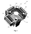
- Fig. 1 shows a convergence system according to a first embodiment of the present invention.
- the convergence system 100 comprises an X-cube 102, three (or more) single intermediate parts 104a, 104b, 104c for three (or more) different colors or color ranges and light modulating means 106a, 106b, 106c for each of these three (or more) different colors.
- the X-cube 102 is a dichroic prism which allows recombination of three outgoing beams having a different color or color range into one beam. Some prisms however act as splitting and recombining mirrors at the same time, e.g. for reflective DMD's or reflective LCD's, such as LCOS-technology.
- the X-cube 102 typically is made of glass preferably with optical quality, and comprises several dichroic coatings, which allow the recombination of three beams into an outgoing beam.
- BK7 which can be obtained from Schott Glas, is one of the most available optical glass types and therefore widely known, but other optical materials, produced by other companies such as Ohara and Corning, also are produced, each with their own specifications such as e.g. their own refractive index.
- X-cubes made of another basic material are seldom but also could be used for the present invention.
- Complete X-cubes, i.e. the basic materials shaped to prisms, the applied coatings and the glue to connect the different parts made in the basic materials, are well known by a person skilled in the art and are available from e.g. Nitto Optical Co., Ltd. or Enplas Optics Corporation or Unaxis Balzers Ltd. Division Optics.
- the X-cube in the present invention can also be used for recombining three different color beams into one single beam. Furthermore, the X-cube in the present invention also can be used for both light splitting and light recombination.
- the three intermediate parts i.e. an intermediate part 104a for color green, an intermediate part 104b for color red and an intermediate part 104c for color blue, are suited for receiving e.g. filters, analyzers or polarizers.
- the present invention includes these intermediate parts being split in a different way and consisting of three separate pins or pillars.
- a spatial light modulating means 106a, 106b, 106c can be any suitable device which comprises an array of individually addressable and individually drivable light modulating pixels, which can be driven to represent an arbitrary image.
- the spatial light modulating means 106a, 106b, 106c can be e.g. a digital mirror device (DMD), a liquid crystal on silicon (LCOS) device, a liquid crystal display (LCD), but is not limited thereto.
- the light modulating means 106a, 106b, 106c can be either reflective or transmissive. The system has the strongest advantage for projectors using light modulating means 106a, 106b, 106c with high resolution.
- a spatial light modulating means 106a for the green light a spatial light modulating means 106b for the red light and a spatial light modulating means 106c for the blue light.
- the intermediate parts 104a, 104b, 104c are made of a specific material or materials.
- This material or these materials has/have a linear coefficient of thermal expansion or a combined average linear coefficient of thermal expansion which is the same as, or as close as possible to, the linear coefficient of thermal expansion of the optical glass used for the X-cube 102 or to the linear coefficient of thermal expansion of the spatial light modulating means 106a, 106b, 106c or to an average linear coefficient of thermal expansion of these means.
- the basic material typically is glass having a good transparency for light with wavelengths in the visible spectrum.
- the type of glass chosen for production of the spatial light modulating means 106a, 106b, 106c can vary and depends on the quality of the spatial light modulating means 106a, 106b, 106c used. Optical grade glass, BK7 as well as simple float glass without special characteristics can be used. The invention furthermore is not limited to spatial light modulating means 106a, 106b, 106c having glass as basic material. Other optical transparent materials such as sapphire or certain liquids also are within the scope of the present invention.
- intermediate parts 104a, 104b, 104c having an average linear coefficient of thermal expansion which is equal or close to the average linear coefficient of thermal expansion of the light modulating means 106a, 106b, 106c, tension and/or movement between the different components is avoided.
- the linear coefficient of thermal expansion should deviate not more than 3.10 -6 /K, preferably not more than 2.10 -6 /K, more preferably not more than 1.10 -6 /K from the linear coefficient of thermal expansion of all the other components that form the complete chain between each spatial light modulating means 106a, 106b, 106c and the used prism for recombining the at least two superposed images. This should preferably apply over the range -30°C to +80°C, i.e.
- this material needs to have a similar specific heat capacity as the X-cube 102 and the glass components of the spatial light modulating means 106a, 106b, 106c, so that they have a similar behavior even in gradient situations, i.e. also in non stable circumstances.
- the specific heat capacity should not deviate more than 200 J/(kg.K), preferably not more than 100 J/(kg.K), more preferably not more than 50 J/(kg.K).
- the stiffness of the materials should also be larger than the stiffness of the materials currently used in conventional systems, i.e.
- This modulus of elasticity should be bigger than 100 GPa, preferably bigger than 200 Gpa.
- the materials also should not suffer significantly from hysteresis or plastic deformation when stressed and behave fully elastic, i.e. come back to their original position when original environmental parameters are obtained.
- the latter elasticity should be obtained for deformation at temperatures that are between -30°C and +80°C, i.e. temperatures that are normal inside a projecting apparatus.
- This elasticity should also be obtained for different humidity conditions, i.e. between 0% and 100% relative humidity. The most important environmental effects thus are variations in temperature and variations in humidity. These can cause mechanical stress in the materials.
- Ceramics e.g. Al 2 O 3
- Al 2 O 3 also has the advantage that it can be shaped to functional parts with a limited amount of production time and costs.
- Ceramic materials that can be used are Zirconia, silicon nitride, boron carbide or silicon carbide.
- Alternative materials with similar linear expansion are e.g. glass as mentioned in Table 1, but also FeNi alloys and thermosetting material such as Bulk Molding Compound (BMC). The linear thermal expansion coefficient, the thermal conductivity and the Young modulus of some of these materials are shown in Table 1.
- the young modulus of BMC is not constant, but comparable to that of plastics such as Polyphenylene Sulphide.
- Each of the intermediate parts 104a, 104b, 106c is fixed onto the X-cube 102 on one side and to the light valve means 106a, 106b, 106c of the corresponding color on the other side, e.g. by glueing.
- the glueing is performed with the least possible amount of play between glue 108 and parts, which is preferably below 0,4 mm, more preferably below 0,3 mm, most preferably below 0,2 mm.
- Glue 108 is used at different places with parameters, matching close with the parameters of all construction parts they connect. Examples of glues 108 that can be used are glues based on acrylate or epoxy that can quickly be cured with UV light or heat, or cements cured by heat. Ceramics and glass alternatively could be bonded together with solder and/or molten glass or other known principles.
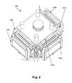
- An alternative view on the convergence system of the first embodiment is shown in Fig. 2.
- a convergence system similar to that of the first embodiment of the present invention having a plurality, e.g. three, intermediate parts 104a, 104b, 104c, which have, however, not only a straight but also a stiff construction.
- the intermediate parts 104a, 104b, 104c are each preferably made of a single part, or at least of the least possible numbers of parts. Therefore, an intermediate part 104a, 104b, 104c is not only made of a stiff material, as discussed in the first embodiment, but also has a stiff construction.
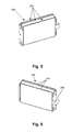
- Straight, stiff bridges 200 as indicated in Fig. 3 and Fig.
- Fig. 3 and Fig. 4 show a left elevated view and right elevated view of part of the intermediate part 104a.
- This stiff construction furthermore still allows guarding the possibility to adjust according to six degrees of freedom. These six degrees of freedom are not obtained by providing additional parts, but are provided inherently in the intermediate parts 104a, 104b, 104c.
- a spatial light modulating means 106a, 106b, 106c together with the translation in the direction of the optical axis, i.e. the Z-axis, can be used to obtain a crisp image on the screen by providing a small amount of play between the three bridges 200, e.g. formed by pins, and the three corresponding acceptance points, e.g. formed by holes, in the spatial light modulating means 106a, 106b, 106c.
- the rotational movements can be used for controlling the sharpness and at the same time the magnification of the image, while the translational movement can be used for controlling the sharpness of the image.
- the three other degrees of freedom namely the movements in the plane of the image, which consist of the vertical and the horizontal translation, together with the rotation in this plane, can be moved to obtain an image, well positioned vertically, horizontally and in rotation on the screen by sliding the intermediate part 104a, 104b, 104c against the dichroic prism, i.e. in this case the X-cube 102. By sliding, the play is also minimized.
- all six degrees of freedom can be fixed with methods as formerly described. This procedure can be repeated for each of the spatial light modulating devices 106a, 106b, 106c.
- the stiff bridges 200 will block an analyzer means in vertical direction.
- analyzer means 202 could not be removed vertically anymore after construction of the convergence system, without removing the stiff bridges 200, i.e. breaking the connection between the spatial light modulating means 106a, 106b, 106c and the X-cube 102.
- the present embodiment solves this problem by providing a way of removing the analyzer means 202 sideways.
- the analyzer means 202 and part of the intermediate parts 104a, 104b, 104c is illustrated in Fig. 5 and Fig. 6, showing an elevated front and an elevated back view of the intermediate parts.
- the analyzer means 202 typically is a set of substrates 204, which can consist of 1, 2, 3 or more substrates 204.
- the analyzer means 202 and the different substrates 204 are fixed without play. This fixation may be performed by glueing. More preferably, the fixing means are such that the analyzer means 202 may be removably fixed.
- Such a fixing means may for example be a clamp 206 or a closing means based on a spring. The sideways fixation thus allows removal of the analyzer means 202 if it reaches the end of its lifetime and provides the possibility for servicing both the analyzer means 202 and the convergence system 100.
- a convergence system similar to one of the convergence systems of the other embodiments of the present invention whereby the images on the screen are symmetric, i.e. so that the symmetry on the screen is kept.
- a first embodiment to obtain symmetry on the screen is by constructing the parts symmetrically, so that when they are subject of changes due to environmental effects, the shrinking or expansion is equal as well in the horizontal direction, i.e. the positive and negative x direction, as in the vertical direction, i.e. the positive and negative y direction. If this is done for each of the color beams, then the expansion or shrinking in e.g. the positive x direction will be equal for all colors and equal to the expansion or shrinking in e.g. the negative x direction. The same principle is valid for the y direction.
- a second embodiment of obtaining symmetrical behavior on the screen is by mirroring parts that are not symmetrical for a specific color.
- the asymmetric part or all parts of the intermediate part 104a that is positioned opposite to the entrance and/or exit side for the white beam will be mirrored against the asymmetric part of the intermediate parts 104b, 104c adjacent the entrance and exit side for the white beam.
- the green intermediate part 104a is mirrored against the red intermediate part 104b and blue intermediate part 104c to make that shift, if there already is any shift left, due to asymmetry of the intermediate parts 104a, 104b, 104c it happens in the same direction on the screen for all three colors, hence without misconvergence.
- Fig. 7 shows a top view of the convergence system whereby mirrored asymmetrical parts are shown so that any drift caused by this is mainly going in the same direction on the screen for all three main colors, hence have no relative convergence drift between the different colors.
- the shape of the intermediate parts 104a, 104b, 104c is adjusted during construction such that a shift for the different color sub images projected on the screen, which shift is caused by environmental influences on the intermediate parts 104a, 104b, 104c, e.g. temperature, humidity, does not lead to a color misconvergence.
- a first way to do this is making the intermediate parts 104a, 104b, 104c all symmetrical in a plane perpendicular to the optical axis of the intermediate parts 104a, 104b, 104c, i.e.
- the intermediate parts 104a, 104b, 104c are not only symmetrical but also have the same size, i.e. their volume preferably differs less than 1%, more preferably less than 0.1%, even more preferably less than 0.01% and most preferably less than 0.001% from the volume of each of the other intermediate parts.
- the shape of the intermediate parts 104a, 104b, 104c does not have to be cylindrical symmetrical, it only has to be symmetrical in the direction that is influenced by subsequent mirroring of the color sub-images in the X-cube. In other words, if in the X-cube image points of the color sub-images are switched from left to right in the image and vice versa, the symmetry in the intermediate part 104a, 104b, 104c also needs to be in the left - right direction.
- the intermediate parts 104a, 104b, 104c are used, but the color sub-images resulting from the spatial light modulating means 106a, 106b, 106c connected to these intermediate parts 104a, 104b, 104c are not mirrored anymore before they are projected on a screen, the shift induced by the intermediate parts 104a, 104b, 104c due to perturbations in one or more environmental factors which affect the dimensions of the intermediate parts 104a, 104b, 104c would be equal, in magnitude and direction, for all color sub-images and thus not visible.
- an X-cube 102 is used, some color sub-images are mirrored while others are not. Therefore an asymmetric shape of the intermediate parts 104a, 104b, 104c will, due to perturbations in one or more environmental factors, cause color misconvergences: e.g.
- a deformation of the color sub-image formed by the spatial light modulating means 106a, 106b, 106c at the right side of the color sub-image will for some color sub-images, which are not mirrored, lead to a deformation at the right side of the color sub-image in a projected image after the X-cube 102, and will for other color sub-images, which are mirrored in the X-cube 102, lead to a deformation at the left side of the color sub-image in a projected image after the X-cube.
- the intermediate parts 104a, 104b, 104c are adjusted such that the color sub-images on the screen will have the same deformation at the same spot in the projected sub-images such that no color misconvergence is seen.
- X-cube mirroring e.g. a sub-image in the left - right direction, i.e.
- the convergence system is adjusted such that the intermediate parts 104a, 104b, 104c for sub-beams that are mirrored in the X-cube 102, have a mirrored shape in the left - right direction compared to intermediate parts 104a, 104b, 104c for sub-beams that are not mirrored in the X-cube 102.
- the mirrored shape is such that it corrects for the color misconvergence due to mirroring of the sub-beams in the X-cube 102.
- the number of times a sub-image is mirrored after passing the spatial light modulating means 106a, 106b, 106c and before it is projected determines whether the intermediate parts 104a, 104b, 104c have a first shape or the mirrored shape. More generally, either all intermediate parts sending a light sub-beam to the light splitting and/or light recombining means, e.g. X-cube 102, that are subsequently mirrored an odd number of times before projection have a mirrored shape, or all the intermediate parts sending a light sub-beam to the light splitting and/or light recombining means, e.g. X-cube 102, that are subsequently not mirrored or mirrored an even number of times have a mirrored shape.
- the light splitting and/or light recombining means e.g. X-cube 102
- the mirroring of the shape of the intermediate part 104a, 104b, 104c is performed with respect to a mirror plane defined by the optical axis of the system, i.e. the direction along the light path, and the direction in which the color sub-images are left invariant by the X-cube 102.
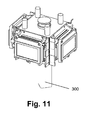
- a convergence system according to any of the previous embodiments of the present invention is provided, whereby furthermore a means 300 for handling the convergence system and for sliding the convergence system in a base plate or chassis of a projection system is provided.
- These means 300 are provided as convergence drift also can be caused by handling by movement of the panel or panel fixation parts due to touching of nearby parts or due to being stored in wrong position.
- the handling means 300, used for handling and guiding typically comprise a grip and a guiding element.
- the guiding element preferably is a non-spherical element, as this allows providing a good orientation of the convergence system in the projection system.
- This guiding element may e.g. be a tube with a polygonal transversal cross-section, e.g.
- a triangular cross-section as shown in Fig. 8, Fig. 9, Fig. 10 and Fig. 11, whereof the bottom may be used to position and slide the convergence system in a corresponding polygonal hole, e.g. a triangular hole, in the base plate of the projector or in the production tools during the production process.
- the same polygonal, e.g. triangular, tube can, at the other side, also be used as a grip to handle the assembly.
- the present invention can be used in a projection display system.
- a light beam of a light source will be focussed by optical components on a convergence system as described in any of the previous embodiments.
- the image formed in the convergence system then is projected on a screen with a projection lens.
- the projected imaged will be a scaled version of an image represented on the spatial light modulating means.
- the projection system furthermore also comprises a base plate for supporting the different components.
- the projection system has all advantages associated with the advantages of the convergence system.
- the embodiments of the present invention have the advantages over the conventional systems that they provide convergence systems that are better fixed, stable over time ad not drifting due to environmental influences as mechanical stress, temperature and humidity. This is performed by combining better materials, in a stiffer construction with an on screen symmetrical behavior and improved means for handling.
- the embodiments of the present invention thus act as much as possible as a solid block, i.e. monolithically.
- the embodiments of the present invention also act isotropically, i.e. the movements of the converged images for all tree colors are in the same directions. This is caused by constructing the convergence system, both for its chain of mainly mechanical parts and for the connection elements, e.g. such as glue, stable in the sub-micrometer range.
Landscapes
- Engineering & Computer Science (AREA)
- Multimedia (AREA)
- Signal Processing (AREA)
- Projection Apparatus (AREA)
- Optical Elements Other Than Lenses (AREA)
Applications Claiming Priority (2)
| Application Number | Priority Date | Filing Date | Title |
|---|---|---|---|
| US785355 | 2004-02-24 | ||
| US10/785,355 US6984042B2 (en) | 2004-02-24 | 2004-02-24 | Convergence system for a projection display system |
Publications (2)
| Publication Number | Publication Date |
|---|---|
| EP1569463A2 true EP1569463A2 (fr) | 2005-08-31 |
| EP1569463A3 EP1569463A3 (fr) | 2009-06-24 |
Family
ID=34750471
Family Applications (1)
| Application Number | Title | Priority Date | Filing Date |
|---|---|---|---|
| EP05002581A Withdrawn EP1569463A3 (fr) | 2004-02-24 | 2005-02-08 | Système de convergence pour un système d'affichage par projection |
Country Status (2)
| Country | Link |
|---|---|
| US (1) | US6984042B2 (fr) |
| EP (1) | EP1569463A3 (fr) |
Cited By (5)
| Publication number | Priority date | Publication date | Assignee | Title |
|---|---|---|---|---|
| EP2280551A1 (fr) * | 2009-07-23 | 2011-02-02 | Christie Digital Systems USA, Inc. | Mécanisme de convergence réglable pour affichages de projection |
| US8167433B2 (en) | 2009-07-23 | 2012-05-01 | Christie Digital Systems Usa, Inc. | Motorized adjustable convergence mechanism for projection displays |
| US8988564B2 (en) | 2011-09-09 | 2015-03-24 | Apple Inc. | Digital camera with light splitter |
| US11029592B2 (en) | 2018-11-20 | 2021-06-08 | Flightsafety International Inc. | Rear projection simulator with freeform fold mirror |
| US11122243B2 (en) | 2018-11-19 | 2021-09-14 | Flightsafety International Inc. | Method and apparatus for remapping pixel locations |
Families Citing this family (9)
| Publication number | Priority date | Publication date | Assignee | Title |
|---|---|---|---|---|
| JP4168854B2 (ja) * | 2003-07-15 | 2008-10-22 | セイコーエプソン株式会社 | 光学装置、およびプロジェクタ |
| US20060082739A1 (en) * | 2004-10-15 | 2006-04-20 | Hsiu Feng Yeh | Panel locating method of a projecting system |
| JP4581769B2 (ja) * | 2005-03-17 | 2010-11-17 | セイコーエプソン株式会社 | プリズム構造体及びプロジェクタ |
| JP4622826B2 (ja) * | 2005-11-25 | 2011-02-02 | セイコーエプソン株式会社 | 光学装置およびプロジェクタ |
| TWI337290B (en) * | 2007-04-09 | 2011-02-11 | Young Optics Inc | Fixing mechanism for fixing a light valve and a thermal module of an optical engine |
| JP4428434B2 (ja) * | 2007-09-28 | 2010-03-10 | セイコーエプソン株式会社 | 光学装置、及びプロジェクタ |
| DE102019120284A1 (de) * | 2018-08-08 | 2020-02-13 | Schott Ag | Spiegel sowie Spiegelträger mit hohem Aspektverhältnis sowie Verfahren und Mittel zur Herstellung eines solchen Spiegelträgers |
| US10694160B2 (en) | 2018-11-20 | 2020-06-23 | Disney Enterprises, Inc. | Channel based projector calibration |
| CN219778078U (zh) * | 2020-01-31 | 2023-09-29 | 夏普Nec显示器解决方案株式会社 | 图像显示装置 |
Family Cites Families (5)
| Publication number | Priority date | Publication date | Assignee | Title |
|---|---|---|---|---|
| USRE38194E1 (en) * | 1996-12-18 | 2003-07-22 | Seiko Epson Corporation | Projection display device |
| JP3794250B2 (ja) * | 2000-07-17 | 2006-07-05 | セイコーエプソン株式会社 | プロジェクタ |
| US6819464B2 (en) * | 2002-06-19 | 2004-11-16 | Seiko Epson Corporation | Optical modulator, optical device and projector |
| US6844993B2 (en) * | 2002-06-19 | 2005-01-18 | Seiko Epson Corporation | Optical device and projector having the optical device |
| JP3736523B2 (ja) * | 2002-12-20 | 2006-01-18 | セイコーエプソン株式会社 | 実装ケース入り電気光学装置及び投射型表示装置並びに実装ケース |
-
2004
- 2004-02-24 US US10/785,355 patent/US6984042B2/en not_active Expired - Fee Related
-
2005
- 2005-02-08 EP EP05002581A patent/EP1569463A3/fr not_active Withdrawn
Cited By (11)
| Publication number | Priority date | Publication date | Assignee | Title |
|---|---|---|---|---|
| EP2280551A1 (fr) * | 2009-07-23 | 2011-02-02 | Christie Digital Systems USA, Inc. | Mécanisme de convergence réglable pour affichages de projection |
| US8162484B2 (en) | 2009-07-23 | 2012-04-24 | Christie Digital Systems Usa, Inc. | Adjustable convergence mechanism for projection displays |
| US8167433B2 (en) | 2009-07-23 | 2012-05-01 | Christie Digital Systems Usa, Inc. | Motorized adjustable convergence mechanism for projection displays |
| US8988564B2 (en) | 2011-09-09 | 2015-03-24 | Apple Inc. | Digital camera with light splitter |
| US9465221B2 (en) | 2011-09-09 | 2016-10-11 | Apple Inc. | Digital camera with light splitter |
| US11122243B2 (en) | 2018-11-19 | 2021-09-14 | Flightsafety International Inc. | Method and apparatus for remapping pixel locations |
| US11595626B2 (en) | 2018-11-19 | 2023-02-28 | Flightsafety International Inc. | Method and apparatus for remapping pixel locations |
| US11812202B2 (en) | 2018-11-19 | 2023-11-07 | Flightsafety International Inc. | Method and apparatus for remapping pixel locations |
| US12192686B2 (en) | 2018-11-19 | 2025-01-07 | Flightsafety International Inc. | Method and apparatus for remapping pixel locations |
| US11029592B2 (en) | 2018-11-20 | 2021-06-08 | Flightsafety International Inc. | Rear projection simulator with freeform fold mirror |
| US11709418B2 (en) | 2018-11-20 | 2023-07-25 | Flightsafety International Inc. | Rear projection simulator with freeform fold mirror |
Also Published As
| Publication number | Publication date |
|---|---|
| EP1569463A3 (fr) | 2009-06-24 |
| US6984042B2 (en) | 2006-01-10 |
| US20050185145A1 (en) | 2005-08-25 |
Similar Documents
| Publication | Publication Date | Title |
|---|---|---|
| US6984042B2 (en) | Convergence system for a projection display system | |
| US6839181B1 (en) | Display apparatus | |
| US6076931A (en) | De-centered lens group for use in an off-axis projector | |
| JP3429291B2 (ja) | プロジェクションディスプレイ装置のプロジェクションレンズ | |
| US6714353B2 (en) | Optical device with a function of homogenizing and color separation, and optical illumination system for a projector using the same | |
| JPH08327900A (ja) | 反射光変調器用オフセット・ズーム・レンズ | |
| US6769779B1 (en) | Housing for mounting modulation and polarization components in alignment with an optical path | |
| US6688748B2 (en) | System and method for using off-axis illumination in a reflective projection system | |
| JP2007011248A (ja) | 投射型表示装置 | |
| US6631039B2 (en) | Optical unit and projector using the same | |
| JP2000075202A (ja) | 投射レンズ及びそれを用いた投射装置 | |
| JP3103822B2 (ja) | 投射型カラー液晶表示装置 | |
| US7416307B2 (en) | Optical apparatus and projection apparatus | |
| EP0746163A1 (fr) | Dispositif d'affichage d'image en couleur par projection | |
| JP2004286767A (ja) | 投射型表示装置 | |
| US6997559B2 (en) | Reflective liquid crystal projector | |
| JP3031329B2 (ja) | コンバーゼンス機構及びそれを使用したプロジェクタ | |
| JP2007183396A (ja) | 投射型表示装置 | |
| JP2001154267A (ja) | プロジェクタ | |
| US20200004030A1 (en) | Projection display apparatus | |
| TWI231883B (en) | Off-axis image projecting system | |
| JP2001211468A (ja) | 投射型表示装置の画素合わせ方法及びそれに用いるチャート | |
| JPH10161121A (ja) | カラー画像表示装置の色調整方法 | |
| JPH11223796A (ja) | 投射装置 | |
| Yina | Analysis of Pico-Projection Technologies and Attempt at Design of Pico-Projection Optics |
Legal Events
| Date | Code | Title | Description |
|---|---|---|---|
| PUAI | Public reference made under article 153(3) epc to a published international application that has entered the european phase |
Free format text: ORIGINAL CODE: 0009012 |
|
| AK | Designated contracting states |
Kind code of ref document: A2 Designated state(s): AT BE BG CH CY CZ DE DK EE ES FI FR GB GR HU IE IS IT LI LT LU MC NL PL PT RO SE SI SK TR |
|
| AX | Request for extension of the european patent |
Extension state: AL BA HR LV MK YU |
|
| PUAL | Search report despatched |
Free format text: ORIGINAL CODE: 0009013 |
|
| AK | Designated contracting states |
Kind code of ref document: A3 Designated state(s): AT BE BG CH CY CZ DE DK EE ES FI FR GB GR HU IE IS IT LI LT LU MC NL PL PT RO SE SI SK TR |
|
| AX | Request for extension of the european patent |
Extension state: AL BA HR LV MK YU |
|
| RIC1 | Information provided on ipc code assigned before grant |
Ipc: H04N 9/31 20060101ALI20090520BHEP Ipc: H04N 9/28 20060101AFI20050520BHEP |
|
| AKX | Designation fees paid | ||
| REG | Reference to a national code |
Ref country code: DE Ref legal event code: 8566 |
|
| STAA | Information on the status of an ep patent application or granted ep patent |
Free format text: STATUS: THE APPLICATION IS DEEMED TO BE WITHDRAWN |
|
| 18D | Application deemed to be withdrawn |
Effective date: 20091229 |