EP1569304A1 - Gegenseitigen verriegelende Abdeckplatte für angrenzende Vertiefungen - Google Patents
Gegenseitigen verriegelende Abdeckplatte für angrenzende Vertiefungen Download PDFInfo
- Publication number
- EP1569304A1 EP1569304A1 EP05100640A EP05100640A EP1569304A1 EP 1569304 A1 EP1569304 A1 EP 1569304A1 EP 05100640 A EP05100640 A EP 05100640A EP 05100640 A EP05100640 A EP 05100640A EP 1569304 A1 EP1569304 A1 EP 1569304A1
- Authority
- EP
- European Patent Office
- Prior art keywords
- cover
- opening
- connector opening
- connector
- electronic device
- Prior art date
- Legal status (The legal status is an assumption and is not a legal conclusion. Google has not performed a legal analysis and makes no representation as to the accuracy of the status listed.)
- Withdrawn
Links
Images




Classifications
-
- B—PERFORMING OPERATIONS; TRANSPORTING
- B26—HAND CUTTING TOOLS; CUTTING; SEVERING
- B26D—CUTTING; DETAILS COMMON TO MACHINES FOR PERFORATING, PUNCHING, CUTTING-OUT, STAMPING-OUT OR SEVERING
- B26D7/00—Details of apparatus for cutting, cutting-out, stamping-out, punching, perforating, or severing by means other than cutting
- B26D7/26—Means for mounting or adjusting the cutting member; Means for adjusting the stroke of the cutting member
- B26D7/2628—Means for adjusting the position of the cutting member
-
- H—ELECTRICITY
- H01—ELECTRIC ELEMENTS
- H01R—ELECTRICALLY-CONDUCTIVE CONNECTIONS; STRUCTURAL ASSOCIATIONS OF A PLURALITY OF MUTUALLY-INSULATED ELECTRICAL CONNECTING ELEMENTS; COUPLING DEVICES; CURRENT COLLECTORS
- H01R13/00—Details of coupling devices of the kinds covered by groups H01R12/70 or H01R24/00 - H01R33/00
- H01R13/44—Means for preventing access to live contacts
- H01R13/447—Shutter or cover plate
-
- B—PERFORMING OPERATIONS; TRANSPORTING
- B26—HAND CUTTING TOOLS; CUTTING; SEVERING
- B26D—CUTTING; DETAILS COMMON TO MACHINES FOR PERFORATING, PUNCHING, CUTTING-OUT, STAMPING-OUT OR SEVERING
- B26D5/00—Arrangements for operating and controlling machines or devices for cutting, cutting-out, stamping-out, punching, perforating, or severing by means other than cutting
- B26D5/02—Means for moving the cutting member into its operative position for cutting
- B26D5/04—Means for moving the cutting member into its operative position for cutting by fluid pressure
-
- B—PERFORMING OPERATIONS; TRANSPORTING
- B26—HAND CUTTING TOOLS; CUTTING; SEVERING
- B26D—CUTTING; DETAILS COMMON TO MACHINES FOR PERFORATING, PUNCHING, CUTTING-OUT, STAMPING-OUT OR SEVERING
- B26D7/00—Details of apparatus for cutting, cutting-out, stamping-out, punching, perforating, or severing by means other than cutting
- B26D7/26—Means for mounting or adjusting the cutting member; Means for adjusting the stroke of the cutting member
- B26D7/2614—Means for mounting the cutting member
Definitions
- the present invention relates to a device having first and second recesses and first and second covers covering respective ones of said recesses.
- setup data has been input into electronic devices, such as camcorders, during manufacturing.
- a connector is provided on the electronic apparatus.
- this connector is not for use by end-users. Consequently, the connector is covered after the setup data has been loaded into the electronic device.
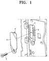
- Figure 1 illustrates one example of a connector unit cover which covers the connector unit of a digital camcorder.
- the digital camcorder's housing 1 has a connector opening 2 that is integrally formed in the body of the camcorder and through which a connector unit 3 for data input is accessible.
- the connector opening 2 has to be covered to prevent access by end-users when all the setup data has been transmitted to the digital camcorder.
- a connector opening cover 4 is provided to block the connector opening 2.
- the connector opening cover 4 is fastened to the digital camcorder's housing 1 by a locking projection 4' formed on one side and a screw 5.
- a device is characterised by said recesses being adjacent one another and said covers being configured to hold each other closed.
- the device may include means, e.g. flexible tab(s) extending from the main part of the first cover, enabling pivoting of the first cover between open and closed positions and the second cover being slidable from the first recess, while open, across the second recess so as to close the second recess.
- means e.g. flexible tab(s) extending from the main part of the first cover, enabling pivoting of the first cover between open and closed positions and the second cover being slidable from the first recess, while open, across the second recess so as to close the second recess.
- the first cover includes a projection which engages the second cover to hold the first cover closed.
- the first recess contains terminals for connection to a battery and the second recess contains an electrical connector.
- the present invention may be implemented in a camcorder.
- the camcorder may include a battery mounting with the recesses located so as to be behind a battery operationally mounted to the battery mounting.
- the housing of an electronic device houses a rechargeable battery mounting unit 10.
- the rechargeable battery mounting unit 10 has a secondary battery receiving unit 10a in which a secondary battery (not shown) is mounted for the maintenance of basic information of the electronic device.
- the secondary battery receiving unit 10a may be opened and closed by a first cover 20.
- the first cover 20 includes a cover body 21 aligned with the open side of the secondary battery receiving unit 10a, a flexible tabs 22, extending from one edge of the cover body 21, and a locking tab 23 ( Figure 6) extending from the opposite edge of the cover body 21.
- the flexible tabs 22 firmly hold the cover body 12 to the rechargeable battery mounting unit 10 and act as a hinge for opening of the cover body 20. More specifically, the flexible tabs 22 are bendable and act as a pivot for the movement of the first cover 20. Thus, the freedom of opening movement of the first cover 20 is increased and, as a result, the user's can more conveniently open the first cover 20.
- the locking tab 23 catches the end of the second cover 100, as described below.
- the locking tab 23 is formed on the edge of the first cover 20 that meets with the second cover 100. Additionally, the end of the locking tab 23 is preferably rounded so that less force is required to release the first cover 20 from the second cover 100.
- a connector opening 10b is formed in communication with the secondary battery receiving unit 10a and provides access to the connector unit 40, which is provided for the input of basic setup data for components of the electronic device.
- the connector unit 40 is provided for the transfer of basic setup data to the electronic device during the manufacture. After the setup data has been entered, the connector unit 40 is covered to limit access by end users.
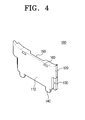
- the second cover 100 has a configuration corresponding to the connector opening 10b so that it fits the connector opening 10b.
- the second cover 100 includes a connector opening cover body 110, a sliding protrusion 120, a guide groove 130, a first locking tabs 140, a nail-receiving recess 150 and a second locking tab 160.
- the connector opening cover body 110 has a configuration corresponding to the connector opening 10b and preferably has same thickness as the first cover 20. Additionally, as shown in Figure 5, the first cover 20 and the connector opening cover body 110 are formed for complementary fitting with each other.
- the sliding protrusions 120 are supported at one end by the guiding tab 11 that protrudes from the inner boundary of the connector opening 10b, and slide along the sliding grooves 12 that is formed along the inner boundary of the connector opening 10b.
- the sliding grooves 12 and the sliding protrusions 120 are formed in complementary configurations.
- the guide grooves 130 are formed in a configuration complementary with the guides 11 and, while the sliding protrusions 120 are slid along the sliding grooves 12, the guiding tabs 11 are slid along the guide grooves 130.
- the sliding protrusion 120, the sliding groove 12, the guide groove 130 and the guiding tab 11 act as rails that guide the sliding movement of the second cover 100 and also prevent the unintended movement of the second cover 100, such as sinking into or moving out of the housing.
- first locking tabs 140 prevent unintended release of the second cover 100 and firmly maintain the locked status of the second cover.
- a plurality of first locking tabs 140 are provided at the lower side of the connector opening cover body 110 extending downwards.
- first locking tab receiving holes 14 are formed in the inner boundary of the connector opening 10b in locations corresponding to the first locking tabs 140 for receiving the first locking tabs 140.
- a nail-receiving recess 150 is provided on an end of the first cover 20 so that a user can raise the connector opening cover using a finger or thumb nail, when releasing the locking tab 23 to open the first cover 20.
- the nail-receiving recess 150 is located at an end of the connector opening cover 110.
- the nail-receiving recess 150 is formed on the end of the connector opening cover body 110 that contacts the first cover 20.
- the second locking tab 160 further prevents the second cover 100 from sliding. More specifically, the second locking tab 160 restricts the second cover 100 from sliding when the first cover 20 is opened such that the second cover 100 is slid only when a certain degree of force is exerted by the user.
- the second locking tab 160 is formed in the face opposite the nail-receiving recess 150.
- a second locking tab receiving hole 13 is formed in a corresponding location in the frame defining the rechargeable battery mounting unit 10 to receive the second locking tab 160.
- the rechargeable battery mounting unit 10 includes a secondary battery receiving unit 10a to receive a secondary battery therein and a connector opening 10b to provide access to the connector unit 40, which is provided for the input of setup data for the electronic device.
- the secondary battery receiving unit 10a is adjacent to the connector opening 10b.
- the secondary battery receiving unit 10a and the connector opening 10b are covered by separate cover members. In this example, the secondary battery receiving unit 10a is covered by the first cover 20 and the connector opening 10b is covered by the second cover 100.
- the first cover 20 completely covers the secondary battery receiving unit 10a, formed in the rechargeable battery mounting unit 10, in complementary engagement with the second cover 100.
- the user inserts a finger nail into the nail-receiving recess 150 and lifts up the first cover 20. Accordingly, the first cover 20 is opened upward as the locking tab 23 is released from the end of the second cover 100, as shown in Figure 6.
- the second cover 100 can be slid upwards and removed. More specifically, as shown in Figure 5, the second cover 100 is restricted from moving upward by the end of the first cover 20 while the first cover 20 is closed, covering the secondary battery receiving unit 10a.
- the first cover 20 is opened, as shown in Figure 6, the second cover 100 is released from its locked condition and, therefore, becomes upwardly slidable.
- the first cover 20 is opened and, with the secondary battery receiving unit 10a in the open, the second cover 100 is slid in the direction indicated by an arrow in Figure 6, thereby separating the second cover from the connector opening 10b as shown in Figure 7.
- Attaching the second cover 100 to cover the connector opening 10b is performed substantially by reversing the above described process. That is, with the first cover 20 in the opened position, the second cover 100 is positioned toward the secondary battery receiving unit 10a as shown in Figure 7. The second cover 100 is then moved toward the end of the connector opening 10b, that is to the closed position, so that the sliding protrusions 120 can be slid along the sliding grooves 12. The second cover 100 is moved until the sliding protrusions 120 are proximal the upper side of the guiding tabs 11 and the guiding tabs 11 are seated in the guide grooves 130 of the second cover 100.
- the first and the second covers 20 and 100 are mutually locked by each other, and therefore, the inconvenience of using separate locking members or separate tools, such as a screwdriver to fix the second cover 100, is prevented. Additionally, breakage of a locking unit due to repeatedly opening and closing the second cover 100 is prevented.
- a connector opening cover unit includes a first cover to open and close the secondary battery receiving unit and a second cover to open and close the connector opening, and the first and the second covers are complimentarily engaged with each other. Because separate fastening means is not required to cover the connector opening according to exemplary embodiments of the present invention, the number of fabricated parts is reduced, and the manufacturing costs are greatly reduced.
Landscapes
- Life Sciences & Earth Sciences (AREA)
- Forests & Forestry (AREA)
- Engineering & Computer Science (AREA)
- Mechanical Engineering (AREA)
- Physics & Mathematics (AREA)
- Fluid Mechanics (AREA)
- Battery Mounting, Suspending (AREA)
- Connector Housings Or Holding Contact Members (AREA)
- Studio Devices (AREA)
Applications Claiming Priority (2)
| Application Number | Priority Date | Filing Date | Title |
|---|---|---|---|
| KR2004013800 | 2004-02-28 | ||
| KR1020040013800A KR20050088000A (ko) | 2004-02-28 | 2004-02-28 | 전자기기의 단자 홀 커버유닛 |
Publications (1)
| Publication Number | Publication Date |
|---|---|
| EP1569304A1 true EP1569304A1 (de) | 2005-08-31 |
Family
ID=34747971
Family Applications (1)
| Application Number | Title | Priority Date | Filing Date |
|---|---|---|---|
| EP05100640A Withdrawn EP1569304A1 (de) | 2004-02-28 | 2005-01-31 | Gegenseitigen verriegelende Abdeckplatte für angrenzende Vertiefungen |
Country Status (5)
| Country | Link |
|---|---|
| US (1) | US7137834B2 (de) |
| EP (1) | EP1569304A1 (de) |
| JP (1) | JP4061315B2 (de) |
| KR (1) | KR20050088000A (de) |
| CN (1) | CN1331274C (de) |
Families Citing this family (6)
| Publication number | Priority date | Publication date | Assignee | Title |
|---|---|---|---|---|
| JP4438862B2 (ja) * | 2007-12-25 | 2010-03-24 | ソニー株式会社 | カメラ装置 |
| CN101807760A (zh) * | 2009-02-17 | 2010-08-18 | 深圳富泰宏精密工业有限公司 | 连接器盖体结构及具该盖体结构的电子装置 |
| CN201781135U (zh) * | 2010-07-27 | 2011-03-30 | 国基电子(上海)有限公司 | 电子装置 |
| US9711886B2 (en) * | 2015-03-30 | 2017-07-18 | Honeywell International Inc. | SD card access door |
| US10015992B2 (en) * | 2016-01-18 | 2018-07-10 | Shenzhen First Union Technology Co., Ltd. | Atomizer and electronic cigarette |
| CN115458874A (zh) * | 2017-01-04 | 2022-12-09 | 米茲寇国际公司 | 具有维持便携式电子装置的防水完整性的电连接器机构的电池组 |
Citations (4)
| Publication number | Priority date | Publication date | Assignee | Title |
|---|---|---|---|---|
| CH677296A5 (en) * | 1989-03-21 | 1991-04-30 | Schurter Ag | Fused electrical appts. plug - has cover providing access to fuse only removable when socket plug is removed |
| JP2000151775A (ja) * | 1998-11-10 | 2000-05-30 | Yupiteru Ind Co Ltd | 携帯電子機器 |
| JP2000324212A (ja) * | 1999-05-10 | 2000-11-24 | Kenwood Corp | 携帯無線電話機 |
| US6352322B1 (en) * | 1997-08-21 | 2002-03-05 | Citizen Watch Co., Ltd. | Portable liquid crystal display device |
Family Cites Families (6)
| Publication number | Priority date | Publication date | Assignee | Title |
|---|---|---|---|---|
| KR920008250A (ko) | 1990-10-15 | 1992-05-27 | 강진구 | 세탁기의 간소화된 헹굼행정 방법 |
| US5199888A (en) * | 1992-01-24 | 1993-04-06 | Compaq Computer Corporation | Apparatus for covering the electrical connectors of a notebook computer |
| JP3369080B2 (ja) * | 1997-07-22 | 2003-01-20 | 富士通株式会社 | 電子装置 |
| JP2000082527A (ja) * | 1998-09-08 | 2000-03-21 | Yazaki Corp | 防水コネクタ |
| KR100403817B1 (ko) | 1999-12-23 | 2003-11-01 | 이성심 | 소각재(바닥재)를 이용한 타일의 제조방법 |
| JP2001320178A (ja) * | 2000-05-02 | 2001-11-16 | Nec Yonezawa Ltd | 電子機器装置 |
-
2004
- 2004-02-28 KR KR1020040013800A patent/KR20050088000A/ko not_active Withdrawn
-
2005
- 2005-01-31 EP EP05100640A patent/EP1569304A1/de not_active Withdrawn
- 2005-02-01 US US11/046,730 patent/US7137834B2/en not_active Expired - Fee Related
- 2005-02-18 JP JP2005042710A patent/JP4061315B2/ja not_active Expired - Fee Related
- 2005-02-28 CN CNB2005100086338A patent/CN1331274C/zh not_active Expired - Fee Related
Patent Citations (4)
| Publication number | Priority date | Publication date | Assignee | Title |
|---|---|---|---|---|
| CH677296A5 (en) * | 1989-03-21 | 1991-04-30 | Schurter Ag | Fused electrical appts. plug - has cover providing access to fuse only removable when socket plug is removed |
| US6352322B1 (en) * | 1997-08-21 | 2002-03-05 | Citizen Watch Co., Ltd. | Portable liquid crystal display device |
| JP2000151775A (ja) * | 1998-11-10 | 2000-05-30 | Yupiteru Ind Co Ltd | 携帯電子機器 |
| JP2000324212A (ja) * | 1999-05-10 | 2000-11-24 | Kenwood Corp | 携帯無線電話機 |
Non-Patent Citations (2)
| Title |
|---|
| PATENT ABSTRACTS OF JAPAN vol. 2000, no. 08 6 October 2000 (2000-10-06) * |
| PATENT ABSTRACTS OF JAPAN vol. 2000, no. 14 5 March 2001 (2001-03-05) * |
Also Published As
| Publication number | Publication date |
|---|---|
| US20050191885A1 (en) | 2005-09-01 |
| CN1661862A (zh) | 2005-08-31 |
| JP4061315B2 (ja) | 2008-03-19 |
| JP2005244971A (ja) | 2005-09-08 |
| KR20050088000A (ko) | 2005-09-01 |
| CN1331274C (zh) | 2007-08-08 |
| US7137834B2 (en) | 2006-11-21 |
Similar Documents
| Publication | Publication Date | Title |
|---|---|---|
| US20060079133A1 (en) | Socket for trans-flash memory card | |
| US7310980B2 (en) | Case for remote control key | |
| US20050202701A1 (en) | Optical connector with shutter | |
| JP2000114740A (ja) | 移動電話機用裏カバ― | |
| CN111433937B (zh) | 电池外壳 | |
| US20060121338A1 (en) | Battery cover assembly and related housing assembly | |
| EP1569304A1 (de) | Gegenseitigen verriegelende Abdeckplatte für angrenzende Vertiefungen | |
| KR20060125396A (ko) | 외장형 카드 탈착장치 | |
| US7014045B2 (en) | Cosmetic compact | |
| JP3773738B2 (ja) | 携帯端末 | |
| EP1705876B1 (de) | Verschlussanordnung für eine Batterieeinheit eines Mobiltelefons, mit einem Schiebedeckel zur Abdeckung eines Kameralinsenmoduls | |
| JP4340410B2 (ja) | デジタルカメラ用クレードル | |
| KR100475095B1 (ko) | 이동통신 단말기의 배터리 충전장치 | |
| US7039209B2 (en) | Cover device for hearing aids | |
| US20100231106A1 (en) | Cap structure | |
| JP2004214969A (ja) | 携帯電子機器 | |
| JP2008263433A (ja) | 電子機器 | |
| KR100606809B1 (ko) | 이동통신 단말기 배터리팩 커버의 로커장치 | |
| JPH11176402A (ja) | 電池蓋構造 | |
| US20230402782A1 (en) | Electrical connector having living hinge and independent secondary terminal lock (isl), and method for operating thereof | |
| JP2004206632A (ja) | Pcカード | |
| KR102839218B1 (ko) | 2중 잠금구조를 갖는 전자제품용 리모컨 | |
| US20040264722A1 (en) | Locking mechanism for electronics module for hearing instruments | |
| KR200319959Y1 (ko) | 이동통신 단말기의 sim 카드 장착구조 | |
| KR100651852B1 (ko) | 휴대용 단말기의 uim 카드 고정장치 |
Legal Events
| Date | Code | Title | Description |
|---|---|---|---|
| PUAI | Public reference made under article 153(3) epc to a published international application that has entered the european phase |
Free format text: ORIGINAL CODE: 0009012 |
|
| AK | Designated contracting states |
Kind code of ref document: A1 Designated state(s): AT BE BG CH CY CZ DE DK EE ES FI FR GB GR HU IE IS IT LI LT LU MC NL PL PT RO SE SI SK TR |
|
| AX | Request for extension of the european patent |
Extension state: AL BA HR LV MK YU |
|
| 17P | Request for examination filed |
Effective date: 20050928 |
|
| AKX | Designation fees paid |
Designated state(s): DE GB NL |
|
| STAA | Information on the status of an ep patent application or granted ep patent |
Free format text: STATUS: THE APPLICATION IS DEEMED TO BE WITHDRAWN |
|
| 18D | Application deemed to be withdrawn |
Effective date: 20090801 |