EP1568968A2 - Nicht-resonante, mikrohergestellte Kreisel mit struktureller Moden-Entkopplung - Google Patents
Nicht-resonante, mikrohergestellte Kreisel mit struktureller Moden-Entkopplung Download PDFInfo
- Publication number
- EP1568968A2 EP1568968A2 EP05004022A EP05004022A EP1568968A2 EP 1568968 A2 EP1568968 A2 EP 1568968A2 EP 05004022 A EP05004022 A EP 05004022A EP 05004022 A EP05004022 A EP 05004022A EP 1568968 A2 EP1568968 A2 EP 1568968A2
- Authority
- EP
- European Patent Office
- Prior art keywords
- mass
- sense
- drive
- dof
- mode oscillator
- Prior art date
- Legal status (The legal status is an assumption and is not a legal conclusion. Google has not performed a legal analysis and makes no representation as to the accuracy of the status listed.)
- Withdrawn
Links
Images


Classifications
-
- G—PHYSICS
- G01—MEASURING; TESTING
- G01C—MEASURING DISTANCES, LEVELS OR BEARINGS; SURVEYING; NAVIGATION; GYROSCOPIC INSTRUMENTS; PHOTOGRAMMETRY OR VIDEOGRAMMETRY
- G01C19/00—Gyroscopes; Turn-sensitive devices using vibrating masses; Turn-sensitive devices without moving masses; Measuring angular rate using gyroscopic effects
- G01C19/56—Turn-sensitive devices using vibrating masses, e.g. vibratory angular rate sensors based on Coriolis forces
- G01C19/5719—Turn-sensitive devices using vibrating masses, e.g. vibratory angular rate sensors based on Coriolis forces using planar vibrating masses driven in a translation vibration along an axis
Definitions
- the invention relates to micromachined gyroscopes and in particular to four-degrees-of-freedom (DOF) nonresonant micromachined gyroscopes having three proof masses.
- DOE four-degrees-of-freedom
- Micromachined gyroscopes are projected to become a potential alternative to expensive and bulky conventional inertial sensors. With micromachining processes allowing mass-production of micromechanical systems on a chip together with their control and signal conditioning electronics, low-cost and microsized gyroscopes provide high accuracy rotation measurements leading to an even broader application spectrum, ranging from advanced automotive safety systems and on-chip navigation systems to interactive consumer electronics.
- the conventional micromachined rate gyroscopes operate on the vibratory principle of a two-degrees-of-freedom (DOF) system with a single proof mass suspended by flexures anchored to the substrate, which allow the mass to oscillate in two orthogonal directions, namely the drive and the sense directions.
- DOF two-degrees-of-freedom
- the proof mass is sustained in resonance in the drive direction, and in the presence of an angular rotation, the Coriolis force proportional to the input angular rate, is induced, exciting the proof mass in the sense direction.
- the drive and the sense resonant frequencies are typically designed and tuned to match, and the device is controlled to operate at or near the peak of the response curve.
- the device is packaged in high vacuum, minimizing energy dissipation due to viscous effects of air surrounding the mechanical structure.
- the overall 4-DOF dynamical system is comprised of three proof masses.
- the 2-DOF sense-direction oscillator is made up of the second and third masses, designed to amplify response in the sense-mode.
- the first mass and the combination of the second and third masses form the 2-DOF drive-direction oscillator.
- the drive and sense-mode oscillators are mechanically decoupled, minimizing instability due to dynamical coupling between the drive and sense modes.
- the frequency response of both of the drive and sense-mode oscillators have two resonant peaks and a flat region between the peaks.
- the flat-region frequency band of the oscillators are overlapped, defining the nominal operation region of the device, where the response gain is less sensitive to parameter variations.
- the invention is a 4-DOF nonresonant micromachined gyroscope comprising a 2-DOF drive-mode oscillator and a 2-DOF sense-mode oscillator, where the drive-mode oscillator and sense-mode oscillators are mechanically decoupled and employ three interconnected proof masses.
- the 2-DOF drive-mode oscillator and 2-DOF sense-mode oscillator utilize dynamical amplification in the drive and sense directions to achieve large oscillation amplitudes without resonance resulting in increased bandwidth and reduced sensitivity to structural and thermal parameter fluctuations and damping changes.
- One of the three masses is an intermediate proof mass and another is a sensing element.
- the 2-DOF drive-mode oscillator and 2-DOF sense-mode oscillator are mechanically decoupled in the drive direction from the sense direction for robustness and long-term stability.
- the Coriolis force that excites the sensing element is generated by the intermediate proof mass with a larger mass, resulting in larger Coriolis forces for increased sensor sensitivity so that control system requirements and tight fabrication and packaging tolerances are relaxed, mode-matching is eliminated, and instability and zero-rate drift due to mechanical coupling between the drive and sense modes is minimized.
- the 2-DOF drive-mode oscillator and 2-DOF sense-mode oscillator include a drive means for driving a mass in a drive direction and a sense means for sensing motion of a mass in a sense direction.
- the three interconnected masses comprise a first, second and third mass.
- the first mass is the only mass excited by the drive means.
- the first mass oscillates in the drive direction and is constrained from movement in the sense direction.
- the second and third masses are constrained from movement with respect to each other in the drive direction and oscillate together in the drive direction but oscillating independently from each other in the sense direction.
- the third mass is fixed with respect to the second mass in the drive direction, but free to oscillate in the sense direction.
- the first mass acts as a driven mass and the second and third masses act collectively as an passive mass to comprise the drive-mode oscillator.
- the second and third masses comprise the sense-mode oscillator.
- the second mass oscillates in the drive and sense directions to generate rotation-induced Coriolis force that excites the 2-DOF sense-mode oscillator.
- a sense direction response is derived from the third mass, which comprises the vibration absorber of the 2-DOF sense-mode oscillator, and is detected for measuring the input angular rate.
- the 2-DOF drive-mode oscillator and 2-DOF sense-mode oscillator include an electrostatic drive for driving a mass in a drive direction, a capacitive sensor for sensing motion of a mass in a sense direction.
- the oscillators are mounted on a substrate.
- the three interconnected masses comprise a first, second and third mass in which the first mass is anchored to the substrate by a first flexure which allows movement substantially only in the drive direction, in which the second mass is coupled to the first mass by a second flexure that allows movement in the drive and the sense directions, and in which the third mass is coupled to the second mass by a third flexure which allows movement substantially only in the sense direction.
- the first, and third flexures are folded micromachined springs having a resiliency substantially in only one direction.
- the second flexure is comprised of two coupled folded micromachined springs, each having a resiliency substantially in only one of two different directions.
- the 2-DOF drive-mode oscillator and 2-DOF sense-mode oscillator each have two resonant peaks and a flat region between the peaks.
- the gyroscope is operated in the flat regions of the drive and sense-mode oscillators.
- the 2-DOF drive-mode oscillator and 2-DOF sense-mode oscillator are arranged and configured to have matching drive and sense direction anti-resonance frequencies.
- the second and the third masses combine to comprise a vibration absorber of the drive-mode oscillator, which vibration absorber mechanically amplifies the oscillations of the first mass.
- the first mass is driven at a driving frequency, ⁇ drive , by means of a input force F d , which driving frequency, ⁇ drive , is matched with the resonant frequency of an isolated passive mass-spring system comprised of the second and third masses and coupled flexures.
- the passive mass-spring system moves to cancel out the input force F d applied to the first mass, so that maximum dynamic amplification is achieved.
- the third mass acts as the vibration absorber in the sense-mode oscillator to achieve large sense direction oscillation amplitudes due to mechanical amplification.
- a sinusoidal Coriolis force is applied to the second mass, whose frequency is matched with a resonant frequency of the isolated passive mass-spring system of the third mass and its coupled flexures, so that the third mass achieves maximum dynamic amplification.
- the frequency response of both the drive-mode oscillator and sense-mode oscillator have two resonant peaks and a flat region between the peaks.
- the drive-mode oscillator and sense-mode oscillator are both operated in the flat region of their response curves.
- the two final terms 2m ⁇ z dy/dt and 2m ⁇ z dx/dt are the rotation-induced Coriolis forces, causing dynamic coupling between the oscillation axes proportional to the angular rate input.
- the proof mass m is driven at or near the resonance frequency in the drive direction by an external sinusoidal force, which are generally the electrostatic forces applied by comb-drive structures.
- an external sinusoidal force which are generally the electrostatic forces applied by comb-drive structures.
- the Coriolis force with the same frequency as the driving signal is induced in the ⁇ -direction. If the drive and sense resonant frequencies are matched, the Coriolis force excites the system into resonance in the sense direction, as well.
- the resulting oscillation amplitude in the sense direction is proportional to the Coriolis force and, thus, to the angular velocity to be measured.
- the rotation-induced Coriolis force F c 2m ⁇ z dx/dt, which is proportional to drive direction oscillation amplitude, is the only driving force in the sense direction for an ideal gyroscope.
- the sense direction amplitude is amplified by the quality factor due to resonance.
- the resonance frequencies are mismatched ⁇ d ⁇ ⁇ x
- the frequency response of the 2-DOF system has two resonant peaks, one at ⁇ x and another at ⁇ y .
- the frequency response of the 2-DOF system has one combined resonant peak, which will provide a much larger response amplitude, leading to the highest sensitivity possible.
- the mode-matching requirement renders the system response very sensitive to variations in system parameters due to fabrication imperfections and fluctuations in operating conditions, which shift the drive or sense resonant frequencies.
- Inevitable fabrication imperfections affect both the geometry and the material properties of MEMS devices.
- the designed stiffness values deviate drastically due to etching processes, deposition conditions, or residual stresses.
- Variations in the temperature of the structure can also perturb the dynamical system parameters due to the temperature dependence of Young's Modulus and thermally induced localized stresses.
- the 4-DOF gyroscope design concept illustrated in this specification eliminates the limitations due to mode-matching requirement, damping sensitivity and coupled oscillation challenges by utilizing mechanically decoupled 2-DOF nonresonant drive and sense oscillators incorporating three proof masses.
- 4-DOF MEMS gyroscopes comprised of two interconnected proof masses have been reported to achieve improved robustness; however, the drive and sense oscillators cannot be mechanically decoupled, and the dynamical response characteristics of the oscillators can't be set independently in these approaches.
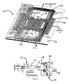
- a 4-DOF micromachined gyroscope system 10 that utilizes dynamical amplification in the decoupled 2-DOF drive oscillators 12 and sense oscillators 14 in order to achieve large oscillation amplitudes without resonance.
- the overall 4-DOF dynamical system 10, namely 2-DOF in drive and 2-DOF in sense directions, is comprised of three interconnected proof masses 16, 18 and 20 as shown in Fig. 1.
- the first mass 16 or m 1 which is the only mass 16 excited in the drive direction, which is here the x direction in Fig. 1, is constrained in the sense direction, which is the y direction in Fig. 1, and is free to oscillate only in the drive direction.
- the second mass 18 or m 2 and third mass 20 or m 3 are constrained with respect to each other in the x drive direction, thus oscillating as one combined mass in the x drive direction.
- masses 18 and 20 are free to oscillate independently in the y sense direction, forming the 2-DOF sense-direction oscillator.
- the first mass 16 and the combination of the second and third masses 18 and 20 form the 2-DOF drive-direction oscillator 12, where mass 16 is the driven mass as diagrammatically depicted in Fig. 2.
- the drive and sense-mode oscillators 12 and 14 are mechanically decoupled.
- the driven mass 16 oscillates only in the x drive direction, and possible anisoelasticities due to fabrication imperfections are suppressed by the suspension 22 fixed in the y sense direction, best shown in Fig. 4.
- the second mass 18 oscillates in both x drive and y sense directions, and generates the rotation-induced Coriolis force that excites the 2-DOF sense-direction oscillator 14.
- the sense direction response of the third mass 20, which comprises the vibration absorber of the 2-DOF sense-mode oscillator 14, is detected for measuring the input angular rate. Since the springs 24 shown in Fig. 2 that couple the sense mass 20 to mass 18 deform only for relative y sense direction oscillations, instability due to mechanical coupling of drive and sense directions is minimized, significantly enhancing gyroscopic performance due to reduced drift.
- the frequency responses of the 2-DOF drive-mode oscillator 12 and the 2-DOF sense-mode oscillator 14 have two resonant peaks and a flat region between the peaks.
- the device 10 is nominally operated in the flat regions of the drive and sense-mode oscillators 12 and 14, where the response amplitudes of the oscillators 12 and 14 are less sensitive to parameter variations.
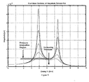
- the flat regions of the oscillators 12 and 14 have to be designed to overlap as depicted in the graph of Fig. 3(a) by matching the drive and sense direction anti-resonance frequencies, as will be explained in below.
- the flat regions with significantly wider bandwidths can be overlapped without feedback control with sufficient precision in spite of fabrication imperfections and operation condition variations.
- the response of the combined 4-DOF dynamical system to the rotation-induced Coriolis force will have a flat region in the frequency band coinciding to the flat regions of the independent drive and sense-mode oscillators as depicted in the graph of Fig. 3(b).
- the oscillation amplitudes in both drive and sense directions are relatively insensitive to variations in system parameters and damping.
- the design concept resulting in improved robustness and long-term stability over the operating time of the device is expected to relax control requirements and tight fabrication and packaging tolerances.
- the proposed design approach allows the widening of the operation frequency range of the gyroscope to achieve improved robustness, while sacrificing the response amplitude in the y sense direction.
- the following numerical example demonstrates the trade-off between bandwidth of the gyroscope and the amplitude of response.
- both gyroscopes are vacuum packaged so that the pressure within the encapsulated cavity is equal to 100 miliTorrs (13.3 Pa), and are both excited to achieve 5 ⁇ m drive-direction oscillation amplitudes.
- the conventional 2-DOF gyroscope will have a 2.8 x 10 -3 ⁇ m response amplitude in the sense direction, while the sense mass of the 4-DOF gyroscope will have an amplitude of response equal to 0.72 x10 -3 ⁇ m.
- the extremely narrow bandwidth of the response (about 1.1 Hz) significantly limits the robustness of the device.
- the design concept allows maximum flexibility in optimizing the system response.
- the optimal compromise between amplitude of the response and bandwidth can be obtained by selecting parameters of the system (ratio of masses and spring constants).
- the gain of the 4-DOF system can be improved by trading-off bandwidth; if the coupling spring constant between the passive and active masses of the 4 DOF gyroscope is increased from 4.2 N/m to 4.8 N/m, the amplitude of the response in the sense direction will increase from 0.72 x 10 -3 ⁇ m to 1.2 x 10 -3 ⁇ m, while the response bandwidth will decrease from 23 Hz to 12 Hz, which is still over an order of magnitude larger than the bandwidth of the conventional gyroscope discussed above.
- the 4-DOF design concept provides more freedom in defining trade-offs between gain of the response (for higher sensitivity) and the system bandwidth (for increased robustness). Selection of the parameter set is typically guided by application requirements.
- the dynamics of the idealized model for the 4-DOF gyroscope system 10 is best understood in the noninertial coordinate frame associated with the gyroscope.
- the 4-DOF system 10 is comprised of three interconnected proof masses 16, 18, and 20 where each mass can be assumed to be a rigid body with a position vector attached to a rotating reference frame , resulting in an absolute acceleration in the inertial frame A where the subscript A denotes "relative to inertial frame A," where B denotes "relative to rotating gyroscope frame B," where v and a are the velocity and acceleration vectors with respect to the designated reference frame respectively, and where ⁇ is the angular velocity vector of the gyroscope frame B relative to the inertial frame A.
- 2 ⁇ x v B is the Coriolis acceleration, which excites the system 10 in the y sense direction.
- Equations of motion for the three proof masses observed in the noninertial rotating frame can be expressed in the inertial frame as where F 1 is the net external vector force applied to mass 16, m 1 , including elastic and damping forces from the substrate and elastic interaction force from mass 18, m 2 ; F 2 is the net external vector force applied to mass 18, m 2 , including the damping force from the substrate and elastic interaction force from and masses 16 and 20; F 3 is the net external vector force applied to mass 20, m 3 , including the damping force from the substrate and the elastic interaction force from mass 18, and is the driving force applied to mass 16.
- 2m 2 ⁇ z dx 2 /dt and 2m 3 ⁇ z dx 3 /dt are the Coriolis forces that excite the system in the y sense direction, and the Coriolis response of mass 20 in the y 3 sense-direction is detected for angular rate measurement.
- the complete suspension subsystem of the device is designed such that the first mass 16 with 1-DOF is fixed in the y sense direction, and is free to oscillate only in the x drive direction, the second mass 18 has 2-DOF, oscillating in both x drive and y sense directions, and the third mass 20 with 1-DOF is fixed with respect to in the x drive direction, and free to oscillate independently in the y sense direction as best shown in the diagrammatic enlargement of Fig. 4.
- the suspension 22 that connects to the substrate 24 via anchors 26 is comprised of four double-folded flexures 28a, 28b, 28c, and 28d, where each beam of length L 1x in the folded flexures 28a, 28b, 28c, and 28d can be modeled as a fixed guided beam deforming in the orthogonal direction to the axis of the beam, leading to an overall stiffness of where E is the Young's Modulus, I is the second moment of inertia of the beam cross-section, t is the beam thickness, and w is the beam width.
- the second mass 18 is connected to mass 16 by four flexure beams comprised of two double-folded flexures 28b and 28c of length L 2x and L 2y that deform independently in the x drive and y sense directions. These beams can also be modeled similarly, resulting in m 2 drive and sense direction stiffness values of
- the suspension 22 connecting the third mass 20 to is made up of four three-folded flexures 28b, 28c and 28d for this specific design, fixing mass 20 with respect to mass 18 in the x drive-direction. Since these flexures 28b, 28c and 28d are stiff in the x drive-direction and deform only in the y sense direction, instability due to dynamical coupling between the drive and sense modes in the sensing element is eliminated, minimizing zero-rate drift of the gyroscope. With a length of L 3y for each beam, the overall stiffness is
- the lengths L 1x , L 2x , L 2y and L 3y are designed according to the optimized stiffness values derived below.
- mechanically decoupled 2-DOF x drive and y sense-mode oscillators are formed with the three proof masses 16, 18 and 20, while instability due to mechanical coupling of x drive and y sense directions is minimized, leading to significantly reduced zero-rate drift.
- the dominant mechanism of energy dissipation in the gyroscope structure is the internal friction of the fluid confined between the proof mass surfaces and the stationary surfaces.
- the damping coefficients C 1x , C 2x , C 3x , and C 3y in the gyroscope dynamical system shown in Fig. 2 are due to the viscous effects of the air between the masses 16, 18 and 20 and the substrate 24, and in between the comb-drive 28 and sense capacitor fingers 30 as shown in Fig. 1.
- the total damping in the drive mode can be approximated as the combination of the slide film damping between the mass 16 and the substrate 24, and the slide film damping between the integrated comb fingers 30.
- slide film damping can be modeled as a Couette flow, leading to where A 1 is the area of the active mass, Z 0 is the elevation of the proof mass from the substrate, t is the thickness of the structure, N comb is the number of comb-drive fingers, y comb is the distance between the fingers, and I comb is the overlapping length of the fingers.
- the approach results in reduced energy dissipation on mass 18, and also symmetric damping in the drive and sense directions.
- the total damping in the drive mode results from Couette flow between the mass 20 and the substrate 24, as well as Couette flow between the air-gap capacitor fingers 28 where A 3 is the area of the passive mass, N cap is the number of air-gap capacitors, y cap is the distance between the capacitor fingers 30, and l cap is the overlapping length of the fingers 30.
- Damping on mass 20 in the sense mode can be estimated as the combination of Couette flow between the proof mass 20 and the substrate 24, and the squeeze-film damping between the air-gap capacitor fingers 30:
- the design approach suggests the sensing mass 20 to have minimal mass in contrast to the conventional gyroscopes. This allows minimizing the overall energy dissipation on the sensing mass 20 due to the reduced footstep area of the mass 20.
- More accurate slide-film damping models can be generated considering the gas-rarefaction effects at low pressures and narrow gaps, kinetic gas models, or plate motions that propagate into the fluid with rapidly diminishing steady-state amplitude. Including the nonlinear effects of squeeze-film damping together with computational fluid dynamics simulations will also improve the accuracy of the damping model.
- the parameters of the dynamical system should be optimized to maximize the oscillation amplitude of mass 20 in the y sense direction.
- the overall 4-DOF gyroscope system 10 can be decomposed into the 2-DOF drive-mode oscillator 12 diagrammatically depicted in Fig. 5(a) and the 2-DOF sense-mode oscillator 14 diagrammatically depicted in Fig. 5(b), analyzed separately below.
- the first mass 16 (which is free to oscillate only in the x drive direction, and is fixed in the y sense direction) and the combination of the second and third masses 18 and 20 (which are fixed with respect to each other in the x drive direction) form the 2-DOF drive-direction oscillator 12, where mass 16 is driven by the electrostatic forces.
- the main objective of parameter optimization in the drive mode is to maximize the rotation- induced Coriolis force generated by the second mass 18.
- This force F c2 2m 2 ⁇ z dx/dt is the dominant force exciting the 2-DOF sense-direction oscillator 14, and is proportional to the sensor sensitivity.
- the gyroscope 10 is simply a 2-DOF system.
- the sinusoidal drive force is applied to the first mass 16 (active mass) by the comb drive structures 28.
- the combination of the second and the third masses 18 and 20 comprise the vibration absorber 36 (passive mass) of the 2-DOF oscillator 12, which mechanically amplifies the oscillations of mass 16.
- ⁇ drive (k 2x /[m 2 + m 3 ]) 1 ⁇ 2
- the passive mass 18 and 20 moves to exactly cancel out the input force F d applied on the active mass, and maximum dynamic amplification is achieved.
- the anti-resonant frequency ⁇ 2x of the isolated passive mass spring system 38 is determined according to gyroscope operating frequency specifications, noting that larger Coriolis forces are induced at higher frequencies, but the oscillation amplitudes become larger at lower frequencies as illustrated in the graph of Fig. 7(b).
- ⁇ 2x is fixed, the drive direction spring constant k 2x is obtained from ⁇ 2x and masses 18 and 20.
- the optimal drive direction mass ratio ⁇ x (m 2 +m 3 )/m 1 determining the mass of the active mass 16 is dictated by low sensitivity to damping, response bandwidth and oscillation amplitude.
- the resonance peaks of the 2-DOF system response have to be separated far enough, which imposes a minimum value of ⁇ x .
- a large ⁇ x is required for large enough separation of the peaks; however, to prevent gain drop, the peak separation should be minimized as illustrated in the graph of Fig. 8(a).
- the optimal frequency ratio ⁇ x has to be determined such that ⁇ x is high enough for high mechanical amplification, and high oscillation amplitudes of passive mass as illustrated in the graph of Fig. 8(b). From the optimal values of ⁇ x and ⁇ 1x , the drive direction spring constant k 1x of the active mass 16 is obtained.
- the damping conditions of the overall device have to be checked to verify that damping values are in the region where the response gain in the antiresonance region is insensitive to damping variations as illustrated by the graph of Fig. 9.
- the 2-DOF sense-direction oscillator 14 in Fig. 5b is formed by masses 18 and 20, where mass 20 acts as the vibration absorber to achieve large sense direction oscillation amplitudes due to mechanical amplification.
- the objective of parameter optimization in the sense mode is to maximize y 3 , which is the sense direction oscillation amplitude of the sensing element 20.
- the dominant force exciting the 2-DOF sense direction oscillator is F c2 , since the mass of the active mass 18 is significantly larger than the mass of the passive mass 20.
- the equations of motion of the lumped mass-spring-damper model of the sense-mode oscillator become
- the frequency of the sinusoidal Coriolis force is matched with the resonant frequency of the isolated passive mass-spring system 40, the passive mass 20 achieves maximum dynamic amplification.
- the frequency response of both of the 2-DOF drive oscillator 12 and sense-mode oscillators 14 have two resonant peaks and a flat region between the peaks. To achieve maximum robustness against fluctuations in the system parameters, both of the 2-DOF oscillators 12 and 14 have to be operated in the flat region of their response curves. Since the Coriolis forces that drive the sense-direction oscillator 14 are at the same frequency as the electrostatic forces exciting the drive-direction oscillator 12, the flat-region frequency band of the oscillators 12 and 14 have to be overlapped, by designing the drive and sense anti-resonance frequencies to match.
- a 4-DOF nonresonant micromachined gyroscope design concept which eliminates the mode-matching requirement, and minimizes instability and zero-rate drift due to mechanical coupling between the drive and sense modes.
- the proposed approach is based on forming mechanically decoupled 2-DOF drive-mode oscillator 12 and DOF sense-mode oscillator 14 using three interconnected proof masses16, 18 and 20.
- the overall 4-DOF system 10 utilizes dynamical amplification in the drive and sense directions to achieve large oscillation amplitudes without resonance resulting in increased bandwidth and reduced sensitivity to structural and thermal parameter fluctuations and damping changes, while mechanically decoupling the drive direction oscillations from the sense direction oscillations leads to improved robustness and long-term stability over the operating time of the device.
Landscapes
- Physics & Mathematics (AREA)
- Engineering & Computer Science (AREA)
- General Physics & Mathematics (AREA)
- Radar, Positioning & Navigation (AREA)
- Remote Sensing (AREA)
- Gyroscopes (AREA)
Applications Claiming Priority (2)
| Application Number | Priority Date | Filing Date | Title |
|---|---|---|---|
| US10/789,037 US7377167B2 (en) | 2004-02-27 | 2004-02-27 | Nonresonant micromachined gyroscopes with structural mode-decoupling |
| US789037 | 2004-02-27 |
Publications (2)
| Publication Number | Publication Date |
|---|---|
| EP1568968A2 true EP1568968A2 (de) | 2005-08-31 |
| EP1568968A3 EP1568968A3 (de) | 2009-12-23 |
Family
ID=34750545
Family Applications (1)
| Application Number | Title | Priority Date | Filing Date |
|---|---|---|---|
| EP05004022A Withdrawn EP1568968A3 (de) | 2004-02-27 | 2005-02-24 | Nicht-resonante, mikrohergestellte Kreisel mit struktureller Moden-Entkopplung |
Country Status (3)
| Country | Link |
|---|---|
| US (1) | US7377167B2 (de) |
| EP (1) | EP1568968A3 (de) |
| JP (1) | JP2005249784A (de) |
Cited By (11)
| Publication number | Priority date | Publication date | Assignee | Title |
|---|---|---|---|---|
| WO2009127782A1 (en) * | 2008-04-16 | 2009-10-22 | Vti Technologies Oy | Vibrating micro-mechanical sensor of angular velocity |
| CN1766528B (zh) * | 2005-11-11 | 2010-09-15 | 中北大学 | 具有较高灵敏度和带宽的差分式微机械陀螺 |
| CN103177164A (zh) * | 2013-04-15 | 2013-06-26 | 北方工业大学 | 一种欠驱动mems角速度陀螺的设计方法 |
| TWI426232B (zh) * | 2010-10-12 | 2014-02-11 | Univ Nat Taiwan | 慣性感測裝置及其使用方法 |
| CN105091875A (zh) * | 2014-05-21 | 2015-11-25 | 因文森斯公司 | 具有解耦驱动系统的mems传感器 |
| EP2570770A3 (de) * | 2011-09-13 | 2016-03-30 | Imec | Dreimassige gekoppelte Oszillationstechnik für mechanisch robuste mikroverarbeitete Gyroskope |
| US9395183B2 (en) | 2011-09-16 | 2016-07-19 | Invensense, Inc. | Micromachined gyroscope including a guided mass system |
| US9863769B2 (en) | 2011-09-16 | 2018-01-09 | Invensense, Inc. | MEMS sensor with decoupled drive system |
| US9958271B2 (en) | 2014-01-21 | 2018-05-01 | Invensense, Inc. | Configuration to reduce non-linear motion |
| US10914584B2 (en) | 2011-09-16 | 2021-02-09 | Invensense, Inc. | Drive and sense balanced, semi-coupled 3-axis gyroscope |
| WO2021109378A1 (zh) * | 2019-12-06 | 2021-06-10 | 深迪半导体(上海)有限公司 | 一种三轴mems陀螺仪 |
Families Citing this family (36)
| Publication number | Priority date | Publication date | Assignee | Title |
|---|---|---|---|---|
| JP2007218608A (ja) * | 2006-02-14 | 2007-08-30 | Denso Corp | 半導体力学量センサ |
| US20090262074A1 (en) * | 2007-01-05 | 2009-10-22 | Invensense Inc. | Controlling and accessing content using motion processing on mobile devices |
| US7796872B2 (en) * | 2007-01-05 | 2010-09-14 | Invensense, Inc. | Method and apparatus for producing a sharp image from a handheld device containing a gyroscope |
| US8020441B2 (en) * | 2008-02-05 | 2011-09-20 | Invensense, Inc. | Dual mode sensing for vibratory gyroscope |
| US7934423B2 (en) | 2007-12-10 | 2011-05-03 | Invensense, Inc. | Vertically integrated 3-axis MEMS angular accelerometer with integrated electronics |
| US8141424B2 (en) | 2008-09-12 | 2012-03-27 | Invensense, Inc. | Low inertia frame for detecting coriolis acceleration |
| US8462109B2 (en) | 2007-01-05 | 2013-06-11 | Invensense, Inc. | Controlling and accessing content using motion processing on mobile devices |
| US8952832B2 (en) | 2008-01-18 | 2015-02-10 | Invensense, Inc. | Interfacing application programs and motion sensors of a device |
| US8508039B1 (en) | 2008-05-08 | 2013-08-13 | Invensense, Inc. | Wafer scale chip scale packaging of vertically integrated MEMS sensors with electronics |
| US8250921B2 (en) | 2007-07-06 | 2012-08-28 | Invensense, Inc. | Integrated motion processing unit (MPU) with MEMS inertial sensing and embedded digital electronics |
| US8047075B2 (en) | 2007-06-21 | 2011-11-01 | Invensense, Inc. | Vertically integrated 3-axis MEMS accelerometer with electronics |
| US8061201B2 (en) * | 2007-07-13 | 2011-11-22 | Georgia Tech Research Corporation | Readout method and electronic bandwidth control for a silicon in-plane tuning fork gyroscope |
| US20100290503A1 (en) * | 2009-05-13 | 2010-11-18 | Prime Photonics, Lc | Ultra-High Temperature Distributed Wireless Sensors |
| TWI384198B (zh) * | 2009-07-09 | 2013-02-01 | Univ Nat Chiao Tung | Angle measurement gyroscope system and angle estimation method |
| US8534127B2 (en) | 2009-09-11 | 2013-09-17 | Invensense, Inc. | Extension-mode angular velocity sensor |
| US9097524B2 (en) | 2009-09-11 | 2015-08-04 | Invensense, Inc. | MEMS device with improved spring system |
| US8549915B2 (en) * | 2009-10-23 | 2013-10-08 | The Regents Of The University Of California | Micromachined gyroscopes with 2-DOF sense modes allowing interchangeable robust and precision operation |
| CN101876547B (zh) * | 2009-12-08 | 2011-11-02 | 北京大学 | 一种采用静电平衡梳齿驱动器的水平轴微机械音叉陀螺 |
| US8381589B2 (en) * | 2010-06-23 | 2013-02-26 | National Chiao Tung University | Single-axis-control-input gyroscope system having imperfection compensation |
| US9714842B2 (en) * | 2011-09-16 | 2017-07-25 | Invensense, Inc. | Gyroscope self test by applying rotation on coriolis sense mass |
| US9170107B2 (en) * | 2011-09-16 | 2015-10-27 | Invensense, Inc. | Micromachined gyroscope including a guided mass system |
| US8896074B2 (en) * | 2012-01-26 | 2014-11-25 | The Charles Stark Draper Laboratory, Inc. | MEMS vibration isolation system and method |
| CN102645211A (zh) * | 2012-04-25 | 2012-08-22 | 哈尔滨工程大学 | 一种四自由度微机械陀螺 |
| CN103398708B (zh) * | 2013-07-15 | 2015-10-21 | 哈尔滨工程大学 | 一种双敏感模态的微机械陀螺 |
| FR3013445B1 (fr) * | 2013-11-20 | 2015-11-20 | Sagem Defense Securite | Capteur a element sensible mobile ayant un fonctionnement mixte vibrant et pendulaire, et procedes de commande d'un tel capteur |
| JP6248576B2 (ja) * | 2013-11-25 | 2017-12-20 | セイコーエプソン株式会社 | 機能素子、電子機器、および移動体 |
| JP6323034B2 (ja) * | 2014-01-28 | 2018-05-16 | セイコーエプソン株式会社 | 機能素子、電子デバイス、電子機器、および移動体 |
| EP2963387B1 (de) | 2014-06-30 | 2019-07-31 | STMicroelectronics Srl | Mikroelektromechanische vorrichtung mit kompensierung von fehlern auf grundlage von störkräften, wie etwa quadraturkomponenten |
| TWI650558B (zh) | 2015-05-20 | 2019-02-11 | 美商路梅戴尼科技公司 | 用於決定慣性參數之方法及系統 |
| CN105242782B (zh) * | 2015-09-25 | 2019-03-29 | 联想(北京)有限公司 | 电子设备和信息处理方法 |
| US10442680B2 (en) * | 2016-06-14 | 2019-10-15 | Mems Drive, Inc. | Electric connection flexures |
| US10234477B2 (en) * | 2016-07-27 | 2019-03-19 | Google Llc | Composite vibratory in-plane accelerometer |
| CN107192384B (zh) * | 2017-07-24 | 2022-04-05 | 深迪半导体(绍兴)有限公司 | 一种mems三轴陀螺仪 |
| JP2020030067A (ja) | 2018-08-21 | 2020-02-27 | セイコーエプソン株式会社 | 物理量センサー、センサーデバイス、電子機器、および移動体 |
| TWI740132B (zh) * | 2019-04-19 | 2021-09-21 | 國立中興大學 | 門檻式陀螺儀 |
| CN119984218B (zh) * | 2025-04-16 | 2025-06-17 | 南京元感微电子有限公司 | 一种双差分单轴陀螺 |
Family Cites Families (12)
| Publication number | Priority date | Publication date | Assignee | Title |
|---|---|---|---|---|
| DE4414237A1 (de) * | 1994-04-23 | 1995-10-26 | Bosch Gmbh Robert | Mikromechanischer Schwinger eines Schwingungsgyrometers |
| DE19827688A1 (de) * | 1997-06-20 | 1999-01-28 | Aisin Seiki | Winkelgeschwindigkeitssensor |
| JPH1144541A (ja) * | 1997-07-29 | 1999-02-16 | Aisin Seiki Co Ltd | 角速度センサ |
| JPH11337344A (ja) * | 1998-05-25 | 1999-12-10 | Murata Mfg Co Ltd | 角速度センサ |
| JP2000009470A (ja) * | 1998-06-18 | 2000-01-14 | Aisin Seiki Co Ltd | 角速度センサ |
| KR100363786B1 (ko) * | 1999-05-13 | 2002-12-11 | 삼성전기주식회사 | 마이크로 자이로스코프 |
| JP3589182B2 (ja) * | 2000-07-07 | 2004-11-17 | 株式会社村田製作所 | 外力計測装置 |
| JP2002022453A (ja) * | 2000-07-11 | 2002-01-23 | Murata Mfg Co Ltd | 振動体装置 |
| JP4635345B2 (ja) * | 2001-01-18 | 2011-02-23 | 株式会社村田製作所 | 角速度センサ |
| DE10108198A1 (de) * | 2001-02-21 | 2002-09-12 | Bosch Gmbh Robert | Drehratensensor |
| WO2002088631A2 (en) * | 2001-05-02 | 2002-11-07 | The Regents Of The University Of California | Non-resonant four degrees-of-freedom micromachined gyroscope |
| JP3870895B2 (ja) * | 2002-01-10 | 2007-01-24 | 株式会社村田製作所 | 角速度センサ |
-
2004
- 2004-02-27 US US10/789,037 patent/US7377167B2/en not_active Expired - Lifetime
-
2005
- 2005-02-24 EP EP05004022A patent/EP1568968A3/de not_active Withdrawn
- 2005-02-28 JP JP2005053238A patent/JP2005249784A/ja active Pending
Cited By (20)
| Publication number | Priority date | Publication date | Assignee | Title |
|---|---|---|---|---|
| CN1766528B (zh) * | 2005-11-11 | 2010-09-15 | 中北大学 | 具有较高灵敏度和带宽的差分式微机械陀螺 |
| CN102066874A (zh) * | 2008-04-16 | 2011-05-18 | Vti技术有限公司 | 振动型微机械角速度传感器 |
| US8176779B2 (en) | 2008-04-16 | 2012-05-15 | Vti Technologies Oy | Vibrating micro-mechanical sensor of angular velocity |
| WO2009127782A1 (en) * | 2008-04-16 | 2009-10-22 | Vti Technologies Oy | Vibrating micro-mechanical sensor of angular velocity |
| TWI426232B (zh) * | 2010-10-12 | 2014-02-11 | Univ Nat Taiwan | 慣性感測裝置及其使用方法 |
| EP2570770A3 (de) * | 2011-09-13 | 2016-03-30 | Imec | Dreimassige gekoppelte Oszillationstechnik für mechanisch robuste mikroverarbeitete Gyroskope |
| US9863769B2 (en) | 2011-09-16 | 2018-01-09 | Invensense, Inc. | MEMS sensor with decoupled drive system |
| US10914584B2 (en) | 2011-09-16 | 2021-02-09 | Invensense, Inc. | Drive and sense balanced, semi-coupled 3-axis gyroscope |
| US12228404B2 (en) | 2011-09-16 | 2025-02-18 | Invensense, Inc. | Drive and sense balanced, semi-coupled 3-axis gyroscope |
| US9395183B2 (en) | 2011-09-16 | 2016-07-19 | Invensense, Inc. | Micromachined gyroscope including a guided mass system |
| US11815354B2 (en) | 2011-09-16 | 2023-11-14 | Invensense, Inc. | Drive and sense balanced, semi-coupled 3-axis gyroscope |
| CN103177164A (zh) * | 2013-04-15 | 2013-06-26 | 北方工业大学 | 一种欠驱动mems角速度陀螺的设计方法 |
| US10527421B2 (en) | 2014-01-21 | 2020-01-07 | Invensense, Inc. | Configuration to reduce non-linear motion |
| US11047685B2 (en) | 2014-01-21 | 2021-06-29 | Invensense, Inc. | Configuration to reduce non-linear motion |
| US9958271B2 (en) | 2014-01-21 | 2018-05-01 | Invensense, Inc. | Configuration to reduce non-linear motion |
| EP2955480A3 (de) * | 2014-05-21 | 2016-03-16 | InvenSense, Inc. | Mems-sensor mit entkoppeltem antriebssystem |
| CN105091875B (zh) * | 2014-05-21 | 2019-08-02 | 应美盛公司 | 具有解耦驱动系统的mems传感器 |
| CN105091875A (zh) * | 2014-05-21 | 2015-11-25 | 因文森斯公司 | 具有解耦驱动系统的mems传感器 |
| WO2021109378A1 (zh) * | 2019-12-06 | 2021-06-10 | 深迪半导体(上海)有限公司 | 一种三轴mems陀螺仪 |
| US11639852B2 (en) | 2019-12-06 | 2023-05-02 | Senodia Technologies (Shaoxing) Co., Ltd. | Three-axis microelectromechanical system (MEMS) gyroscope |
Also Published As
| Publication number | Publication date |
|---|---|
| EP1568968A3 (de) | 2009-12-23 |
| JP2005249784A (ja) | 2005-09-15 |
| US7377167B2 (en) | 2008-05-27 |
| US20050199061A1 (en) | 2005-09-15 |
Similar Documents
| Publication | Publication Date | Title |
|---|---|---|
| US7377167B2 (en) | Nonresonant micromachined gyroscopes with structural mode-decoupling | |
| Acar et al. | Nonresonant micromachined gyroscopes with structural mode-decoupling | |
| US7284430B2 (en) | Robust micromachined gyroscopes with two degrees of freedom sense-mode oscillator | |
| US6845669B2 (en) | Non-resonant four degrees-of-freedom micromachined gyroscope | |
| US7421898B2 (en) | Torsional nonresonant z-axis micromachined gyroscope with non-resonant actuation to measure the angular rotation of an object | |
| US8443667B2 (en) | Temperature-robust MEMS gyroscope with 2-DOF sense-mode addressing the tradeoff between bandwith and gain | |
| Acar et al. | Inherently robust micromachined gyroscopes with 2-DOF sense-mode oscillator | |
| Acar et al. | MEMS vibratory gyroscopes: structural approaches to improve robustness | |
| US9551576B2 (en) | MEMS inertial sensor and method of inertial sensing | |
| JP3950925B2 (ja) | マイクロメカニック回転速度センサ | |
| US7100446B1 (en) | Distributed-mass micromachined gyroscopes operated with drive-mode bandwidth enhancement | |
| JP5705953B2 (ja) | 慣性センサ | |
| US11125632B2 (en) | Piezoresistive detection resonant device in particular with large vibration amplitude | |
| US6928874B2 (en) | Dynamically amplified micromachined vibratory angle measuring gyroscopes, micromachined inertial sensors and method of operation for the same | |
| US6658937B2 (en) | Oscillatory angular rate sensor | |
| US20160349053A1 (en) | Micromachined Resonating Beam Gyroscopes | |
| Acar et al. | Microgyroscopes with dynamic disturbance rejection | |
| Acar et al. | A design approach for robustness improvement of rate gyroscopes | |
| Acar et al. | Distributed-mass micromachined gyroscopes for enhanced mode-decoupling | |
| Acar et al. | Design concept and preliminary experimental demonstration of MEMS gyroscopes with 4-dof master-slave architecture | |
| Park et al. | Laterally self-oscillated and force-balanced microvibratory gyroscope packaged in a vacuum package with a conditioning ASIC | |
| Acar | Design Concept and Preliminary Experimental Demonstration of 4-DOF MEMS Gyroscopes | |
| Shkel | Enhancement of drive-mode bandwidth in MEMS vibratory gyroscopes utilizing multiple oscillators | |
| Acar et al. | A class of micromachined gyroscopes with increased parametric space | |
| Acar et al. | MEMS Gyroscopes with Structurally Decoupled |
Legal Events
| Date | Code | Title | Description |
|---|---|---|---|
| PUAI | Public reference made under article 153(3) epc to a published international application that has entered the european phase |
Free format text: ORIGINAL CODE: 0009012 |
|
| AK | Designated contracting states |
Kind code of ref document: A2 Designated state(s): AT BE BG CH CY CZ DE DK EE ES FI FR GB GR HU IE IS IT LI LT LU MC NL PL PT RO SE SI SK TR |
|
| AX | Request for extension of the european patent |
Extension state: AL BA HR LV MK YU |
|
| RIN1 | Information on inventor provided before grant (corrected) |
Inventor name: ACAR,CENK Inventor name: SHKEL,ANDREI M. |
|
| PUAL | Search report despatched |
Free format text: ORIGINAL CODE: 0009013 |
|
| AK | Designated contracting states |
Kind code of ref document: A3 Designated state(s): AT BE BG CH CY CZ DE DK EE ES FI FR GB GR HU IE IS IT LI LT LU MC NL PL PT RO SE SI SK TR |
|
| AX | Request for extension of the european patent |
Extension state: AL BA HR LV MK YU |
|
| AKX | Designation fees paid |
Designated state(s): AT BE BG CH CY CZ DE DK EE ES FI FR GB GR HU IE IS IT LI LT LU MC NL PL PT RO SE SI SK TR |
|
| STAA | Information on the status of an ep patent application or granted ep patent |
Free format text: STATUS: THE APPLICATION IS DEEMED TO BE WITHDRAWN |
|
| 18D | Application deemed to be withdrawn |
Effective date: 20100617 |