EP1568807A2 - Ensemble de rouleaux pour une machine pour fabrication d'un fil auto-torsadé et procédé de fabrication d'un fil auto-torsadé - Google Patents
Ensemble de rouleaux pour une machine pour fabrication d'un fil auto-torsadé et procédé de fabrication d'un fil auto-torsadé Download PDFInfo
- Publication number
- EP1568807A2 EP1568807A2 EP04029752A EP04029752A EP1568807A2 EP 1568807 A2 EP1568807 A2 EP 1568807A2 EP 04029752 A EP04029752 A EP 04029752A EP 04029752 A EP04029752 A EP 04029752A EP 1568807 A2 EP1568807 A2 EP 1568807A2
- Authority
- EP
- European Patent Office
- Prior art keywords
- roller
- rovings
- guide
- yarn
- guide roller
- Prior art date
- Legal status (The legal status is an assumption and is not a legal conclusion. Google has not performed a legal analysis and makes no representation as to the accuracy of the status listed.)
- Granted
Links
Images



Classifications
-
- D—TEXTILES; PAPER
- D02—YARNS; MECHANICAL FINISHING OF YARNS OR ROPES; WARPING OR BEAMING
- D02G—CRIMPING OR CURLING FIBRES, FILAMENTS, THREADS, OR YARNS; YARNS OR THREADS
- D02G3/00—Yarns or threads, e.g. fancy yarns; Processes or apparatus for the production thereof, not otherwise provided for
- D02G3/22—Yarns or threads characterised by constructional features, e.g. blending, filament/fibre
- D02G3/26—Yarns or threads characterised by constructional features, e.g. blending, filament/fibre with characteristics dependent on the amount or direction of twist
- D02G3/28—Doubled, plied, or cabled threads
- D02G3/286—Doubled, plied, or cabled threads with alternatively "S" and "Z" direction of twist, e.g. Self-twist process
-
- B—PERFORMING OPERATIONS; TRANSPORTING
- B26—HAND CUTTING TOOLS; CUTTING; SEVERING
- B26B—HAND-HELD CUTTING TOOLS NOT OTHERWISE PROVIDED FOR
- B26B19/00—Clippers or shavers operating with a plurality of cutting edges, e.g. hair clippers, dry shavers
- B26B19/02—Clippers or shavers operating with a plurality of cutting edges, e.g. hair clippers, dry shavers of the reciprocating-cutter type
- B26B19/04—Cutting heads therefor; Cutters therefor; Securing equipment thereof
- B26B19/044—Manufacture and assembly of cutter blocks
Definitions
- the invention relates to a roller assembly for a device for producing a Self-twisting yarn according to the preamble of claim 1, an apparatus for manufacturing a self twisting yarn comprising such a roll arrangement and a method for the Production of a self-twisting yarn according to the preamble of claim 12.
- a generic method for producing a self-twisting yarn and a Apparatus for carrying out this method is known from DE 100 32 708 C1.
- first at least two rovings are alternately provided with areas of and Z rotations separated by areas without rotation.
- These rovings are then combined on a guide roll so that they automatically twist together due to their tendency to reverse, the areas without Rotation in the twisted self-twisting yarn have a phase difference.
- These Phase difference is adjusted by placing one of the rovings over a pulley and from There is led to the leadership role, making this roving compared to the other Roving has a longer way to go until it becomes unified with the other Roving is coming.
- the invention is based on the object, a method and a To provide apparatus for producing a self-twisting yarn with which a twisted self-twisting yarn can be produced, which is characterized by a uniform Phase course of the unrotated portions of the rovings along the twisted Self-twisting yarn distinguishes.
- the invention proposes a roller assembly for a Apparatus for producing a self-twisting yarn having the features of claim 1 and a set of roller assemblies according to claim 5.
- preferred Embodiments of the roller assembly can be found in the dependent claims 2 to 4.
- each The roving gives false twists, so that each roving is alternating areas with Has S and Z turns. Then these rovings are brought together in such a way that they twine themselves to the self-twisting yarn.
- the Reverse tendency of the rovings provided with incorrect rotations exploited It is known, that the strength of the twisted twisting yarn is quite different from the Phase of the areas without rotation of the two rovings depends. The rovings will be Therefore, as a rule, merged so that their areas without rotation out of phase lie.
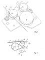
- Figures 1 and 2 this is illustratively contrasted with the figure 1 the Situation shows, in which the two rovings 2, 3 arranged parallel next to each other are where the areas without rotation (0) face each other or in phase.
- Figure 2 shows the higher for the production of a self-twisting yarn Strength preferred situation in which the areas without rotation (0) of the two rovings 2, 3 out of phase.
- the phase difference between the unrolled areas of the rovings 2, 3 is denoted by ⁇ below.
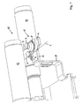
- Figure 7 shows a perspective view of an apparatus for producing a Self-twisting yarn 1 from two rovings 2 and 3.
- the rovings 2, 3 are first in a Not shown here drafting generated and then parallel next to each other running guided in a false twisting device 10.
- the false twisting device 10 the rovings 2, 3 periodically alternately issued areas with S and Z turns, which are separated by areas without rotation (0).
- the rovings 2, 3 After going through the Wrong turning device 10, the rovings 2, 3 in a twisting device 11 so brought together, that they twist together because of their backward tendency and to twist together to the self-twisting yarn 1.
- the false twisting device 10 is as Nitschel device formed. This has two substantially cylindrical and Axially parallel arranged Nitschelwalzen 12, 13 on.
- the Nitschelwalzen 12, 13 rotate on the one hand in opposite directions to each other about their axes of rotation 12a, 13a, which parallel are arranged to each other.
- the rotational movement of the rovings 2, 3 by the Nitschelwalzen 12, 13 promoted.
- the rovings In an oscillation direction, the rovings get an S-twist and in the opposite Zziallationscardi a Z-rotation. Since the Nitschelwalzen 12, 13 at resting at the reversal points of their axial movement, the rovings 2, 3 receive them Time points no rotation. Therefore, the alternating areas are with S and Z turns through areas without rotation (0) or areas with less rotation separated.
- Wrong turning devices are used, such.
- the twisting device 11, in which the rovings 2, 3 then twisted together comprises a roller assembly, which a first guide roller 5, a second Deflection pulley 7 and a guide roller 6 comprises.
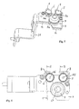
- This roller arrangement is in FIG. 3 shown schematically and in Figures 4 to 6 in detail.
- the rollers 5, 6 and 7 are each mounted in the above arrangement on a base plate 4.
- Thread guides 8 and 9 are respectively Thread guides 8 and 9 arranged.
- the yarn guides 8, 9 serve the roving 2 on the Outer circumference of the guide roller 6 and the roving 3 on the outer circumference of the first Steering pulley 5.
- the yarn guide 8 with respect to its associated Guide roller 6 is arranged so that the roving 2 is deflected so that it only punctiform bears on the merge point 22 on the outer circumference of the guide roller 6.
- the yarn guide 9 serves the roving 3 on the outer circumference of the first guide roller fifth to lead, wherein the first bearing point of the roving 3 on the guide roller 5 in the following designated by reference numeral 33.
- Points 22 and 33 have each one same distance to the Nitschelwalzen 12, 13. From the contact point 33 wraps around the one roving 3 then a substantial part of the circumference of the second guide roller 7 (at the arrangement shown in Figure 4, the wrap angle is about 270 °).
- the Path difference between the attachment point 33 and the merge point 22 determined the phase difference ⁇ between the unrotated portions of the rovings in Twisted self-twisting yarn. For this reason, the exact adherence to the Points 22 and 33 are of particular importance throughout the duration of the proceedings Concerning the uniformity of the manufactured self-twisting yarn 1.
- the roller assembly comprises the Base plate 4 and an intermediate plate 14. On the base plate 4 are the two Deflection rollers 5 and 7 and the guide roller 6 are arranged. The second guide roller 7 is while a bearing 15 rotatably mounted in a receiving plate 16 which on the base plate. 4 is attached, stored.
- the pulleys 5 and 7 and the guide roller 6 are respectively Cylindrically shaped, wherein in the cylinder jacket in each case a guide groove 5a, 6a or 7a is cut.
- the guide grooves are used to run over the respective role Roving 2, 3 on the cylinder surface of the deflection or guide rollers 5, 6, 7 to hold and prevent slipping.
- Thread guide 8 and 9 On the base plate 4 are still the two Thread guide 8 and 9 attached, which in the embodiment described here as Thread guide eyelets are formed. Alternatively, thread guide pins can be used become.
- the guide roller 6 here is the yarn guide 8 and the first guide roller 5 is associated with the thread guide 9.
- the yarn guides 8 and 9 are in this case arranged so that they are in Garnlaufraum C immediately before the guide roller 6 and the guide roller 5 are.
- the base plate 4 is attached via a quick release on the intermediate plate 14.
- a quick release on the intermediate plate 14 is the quick release by two permanent magnets 17, 18 formed, which are inserted in recesses 19, 20 of the intermediate plate.
- the Metallic base plate is characterized by the magnetic force of the magnets 17, 18 on the Intermediate plate 14 held.
- this magnet quick release can also other quick fasteners, such. B. a bayonet closure, are used.
- This holder 21 serves to hold the intermediate plate 14 in the device for Production of a self twisting yarn as shown in FIG.
- a set of roller assemblies which consists of a plurality of Roller assemblies consists, as shown in Figures 4 to 6 and 9.
- the individual role arrangements of this sentence are identical in their structure to those in However, they differ in the FIGS. 4 to 6 and 9 Distance D between the axis A7 of the second guide roller 7 and the plane E, which by the axes A5 and A6 of the first guide roller 5 and the guide roller 6 is defined. through of the quick release, it is possible to have one roller assembly against another Replacing roller assembly in a simple and fast way.
- the Twisted self-twisting yarn (1) immediately after leaving the guide roller (6) is guided over a run-out yarn guide. This will provide a stable guidance of the twisted self-twisting yarn 1 allows.
- the outlet yarn guide is here also like the thread guides 8 and 9 as a thread guide eye or as a thread guide pin educated.
Landscapes
- Engineering & Computer Science (AREA)
- Mechanical Engineering (AREA)
- Textile Engineering (AREA)
- Manufacturing & Machinery (AREA)
- Life Sciences & Earth Sciences (AREA)
- Forests & Forestry (AREA)
- Yarns And Mechanical Finishing Of Yarns Or Ropes (AREA)
- Spinning Or Twisting Of Yarns (AREA)
- Ropes Or Cables (AREA)
Priority Applications (1)
| Application Number | Priority Date | Filing Date | Title |
|---|---|---|---|
| PL04029752T PL1568807T3 (pl) | 2004-01-17 | 2004-12-16 | Układ rolkowy dla urządzenia do wytwarzania przędzy samoskrętnej oraz sposób wytwarzania przędzy samoskrętnej |
Applications Claiming Priority (2)
| Application Number | Priority Date | Filing Date | Title |
|---|---|---|---|
| DE102004002502A DE102004002502B3 (de) | 2004-01-17 | 2004-01-17 | Rollenanordnung für eine Vorrichtung zur Herstellung eines Selbstzwirngarns sowie Verfahren zur Herstellung eines Selbstzwirngarns |
| DE102004002502 | 2004-01-17 |
Publications (3)
| Publication Number | Publication Date |
|---|---|
| EP1568807A2 true EP1568807A2 (fr) | 2005-08-31 |
| EP1568807A3 EP1568807A3 (fr) | 2006-05-03 |
| EP1568807B1 EP1568807B1 (fr) | 2007-07-25 |
Family
ID=34042362
Family Applications (1)
| Application Number | Title | Priority Date | Filing Date |
|---|---|---|---|
| EP04029752A Expired - Lifetime EP1568807B1 (fr) | 2004-01-17 | 2004-12-16 | Ensemble de rouleaux pour une machine pour fabrication d'un fil auto-torsadé et procédé de fabrication d'un fil auto-torsadé |
Country Status (7)
| Country | Link |
|---|---|
| EP (1) | EP1568807B1 (fr) |
| KR (1) | KR20050075698A (fr) |
| CN (1) | CN1641084B (fr) |
| AT (1) | ATE368140T1 (fr) |
| DE (2) | DE102004002502B3 (fr) |
| ES (1) | ES2286555T3 (fr) |
| PL (1) | PL1568807T3 (fr) |
Families Citing this family (1)
| Publication number | Priority date | Publication date | Assignee | Title |
|---|---|---|---|---|
| CN103938320B (zh) * | 2014-04-14 | 2016-08-17 | 上海八达纺织印染服装有限公司 | 一种涤棉自捻纱线的加工方法 |
Family Cites Families (2)
| Publication number | Priority date | Publication date | Assignee | Title |
|---|---|---|---|---|
| DD103464A1 (fr) * | 1972-05-24 | 1974-01-20 | ||
| DE10032708C1 (de) * | 2000-07-07 | 2002-01-31 | Hamel Ag Arbon | Verfahren und Vorrichtung zur Herstellung eines Selbstzwirngarns |
-
2004
- 2004-01-17 DE DE102004002502A patent/DE102004002502B3/de not_active Expired - Fee Related
- 2004-12-16 DE DE502004004430T patent/DE502004004430D1/de not_active Expired - Lifetime
- 2004-12-16 PL PL04029752T patent/PL1568807T3/pl unknown
- 2004-12-16 ES ES04029752T patent/ES2286555T3/es not_active Expired - Lifetime
- 2004-12-16 AT AT04029752T patent/ATE368140T1/de not_active IP Right Cessation
- 2004-12-16 EP EP04029752A patent/EP1568807B1/fr not_active Expired - Lifetime
-
2005
- 2005-01-11 KR KR1020050002683A patent/KR20050075698A/ko not_active Withdrawn
- 2005-01-17 CN CN2005100023199A patent/CN1641084B/zh not_active Expired - Fee Related
Also Published As
| Publication number | Publication date |
|---|---|
| EP1568807A3 (fr) | 2006-05-03 |
| PL1568807T3 (pl) | 2007-12-31 |
| CN1641084A (zh) | 2005-07-20 |
| DE502004004430D1 (de) | 2007-09-06 |
| CN1641084B (zh) | 2010-05-26 |
| EP1568807B1 (fr) | 2007-07-25 |
| ES2286555T3 (es) | 2007-12-01 |
| ATE368140T1 (de) | 2007-08-15 |
| DE102004002502B3 (de) | 2005-02-10 |
| KR20050075698A (ko) | 2005-07-21 |
Similar Documents
| Publication | Publication Date | Title |
|---|---|---|
| DE2758362A1 (de) | Verfahren und vorrichtung zur herstellung eines selbstverdrallten garnes und nach dem verfahren hergestelltes garn | |
| DE2620118B2 (de) | Vorrichtung zum Spinnen von Fasergarn | |
| DE10032708C1 (de) | Verfahren und Vorrichtung zur Herstellung eines Selbstzwirngarns | |
| DE3415459C2 (de) | Fadenliefervorrichtung | |
| EP1664408A1 (fr) | Procede et dispositif pour produire un fil a ame ou un fil a effet ame | |
| DE2942385C2 (de) | Verbindung von langgestreckten Faserverbänden, Verfahren zur Erzeugung einer solchen Verbindung und Vorrichtung zum Durchführen dieses Verfahrens | |
| DE3013995C2 (de) | Vorrichtung zur Herstellung von Effektgarn | |
| EP4273310B1 (fr) | Procédé de fabrication d'un fil à âme | |
| EP1630269A2 (fr) | Guide-fil | |
| DE102004002502B3 (de) | Rollenanordnung für eine Vorrichtung zur Herstellung eines Selbstzwirngarns sowie Verfahren zur Herstellung eines Selbstzwirngarns | |
| DE1785265A1 (de) | Verfahren und Vorrichtung zur Herstellung von zwirnungsgekraeuselten Fadengarnen | |
| EP0591825B1 (fr) | Procédé et dispositif pour le traitement d'au moins deux fils synthétiques en mouvement distant l'un par rapport à l'autre sur une machine textile | |
| DE202004000666U1 (de) | Rollenanordnung für eine Vorrichtung zur Herstellung eines Selbstzwirngarns | |
| DE102005050362A1 (de) | Musterschärer, Musterschärungsverfahren, und Drehgatter | |
| DE3341474C2 (fr) | ||
| DE1660210A1 (de) | Vorrichtung zur Fadentrennung fuer Falschdraht-Kraeuselmaschinen | |
| DE102020118327A1 (de) | Verfahren und Vorrichtung zur Falschdrahteinleitung sowie Spinnmaschine | |
| DE3006863A1 (de) | Vorrichtung zur herstellung von effektgarn | |
| DE102018006984A1 (de) | Effektgarnherstellung mit einer Offenend-Rotorspinneinrichtung | |
| DE2463074C2 (de) | Einprozeß-Zwirnmaschine zur Erzeugung von Zwirn aus zwei Strängen | |
| DE10132865B4 (de) | Trennfadenführer für eine Spinnanlage und Spinnanlage mit einem solchen Trennfadenführer | |
| DE319323C (de) | Fluegelspinnmaschine, insbesondere zur Herstellung von Bindegarn | |
| DE3741064C2 (fr) | ||
| DE2151924C3 (de) | Vorrichtung zur Herstellung von Chenillefäden | |
| DE2945799C2 (de) | Einrichtung zum Umwinden eines Kernfadens |
Legal Events
| Date | Code | Title | Description |
|---|---|---|---|
| PUAI | Public reference made under article 153(3) epc to a published international application that has entered the european phase |
Free format text: ORIGINAL CODE: 0009012 |
|
| AK | Designated contracting states |
Kind code of ref document: A2 Designated state(s): AT BE BG CH CY CZ DE DK EE ES FI FR GB GR HU IE IS IT LI LT LU MC NL PL PT RO SE SI SK TR |
|
| AX | Request for extension of the european patent |
Extension state: AL BA HR LV MK YU |
|
| PUAL | Search report despatched |
Free format text: ORIGINAL CODE: 0009013 |
|
| AK | Designated contracting states |
Kind code of ref document: A3 Designated state(s): AT BE BG CH CY CZ DE DK EE ES FI FR GB GR HU IE IS IT LI LT LU MC NL PL PT RO SE SI SK TR |
|
| AX | Request for extension of the european patent |
Extension state: AL BA HR LV MK YU |
|
| 17P | Request for examination filed |
Effective date: 20061103 |
|
| AKX | Designation fees paid |
Designated state(s): AT BE BG CH CY CZ DE DK EE ES FI FR GB GR HU IE IS IT LI LT LU MC NL PL PT RO SE SI SK TR |
|
| GRAP | Despatch of communication of intention to grant a patent |
Free format text: ORIGINAL CODE: EPIDOSNIGR1 |
|
| GRAS | Grant fee paid |
Free format text: ORIGINAL CODE: EPIDOSNIGR3 |
|
| GRAA | (expected) grant |
Free format text: ORIGINAL CODE: 0009210 |
|
| AK | Designated contracting states |
Kind code of ref document: B1 Designated state(s): AT BE BG CH CY CZ DE DK EE ES FI FR GB GR HU IE IS IT LI LT LU MC NL PL PT RO SE SI SK TR |
|
| REG | Reference to a national code |
Ref country code: GB Ref legal event code: FG4D Free format text: NOT ENGLISH |
|
| REG | Reference to a national code |
Ref country code: CH Ref legal event code: EP Ref country code: CH Ref legal event code: NV Representative=s name: LUCHS & PARTNER PATENTANWAELTE |
|
| REG | Reference to a national code |
Ref country code: IE Ref legal event code: FG4D Free format text: LANGUAGE OF EP DOCUMENT: GERMAN |
|
| REF | Corresponds to: |
Ref document number: 502004004430 Country of ref document: DE Date of ref document: 20070906 Kind code of ref document: P |
|
| REG | Reference to a national code |
Ref country code: RO Ref legal event code: EPE |
|
| GBT | Gb: translation of ep patent filed (gb section 77(6)(a)/1977) |
Effective date: 20071105 |
|
| REG | Reference to a national code |
Ref country code: ES Ref legal event code: FG2A Ref document number: 2286555 Country of ref document: ES Kind code of ref document: T3 |
|
| ET | Fr: translation filed | ||
| REG | Reference to a national code |
Ref country code: PL Ref legal event code: T3 |
|
| PG25 | Lapsed in a contracting state [announced via postgrant information from national office to epo] |
Ref country code: IS Free format text: LAPSE BECAUSE OF FAILURE TO SUBMIT A TRANSLATION OF THE DESCRIPTION OR TO PAY THE FEE WITHIN THE PRESCRIBED TIME-LIMIT Effective date: 20071125 Ref country code: BG Free format text: LAPSE BECAUSE OF FAILURE TO SUBMIT A TRANSLATION OF THE DESCRIPTION OR TO PAY THE FEE WITHIN THE PRESCRIBED TIME-LIMIT Effective date: 20071025 Ref country code: NL Free format text: LAPSE BECAUSE OF FAILURE TO SUBMIT A TRANSLATION OF THE DESCRIPTION OR TO PAY THE FEE WITHIN THE PRESCRIBED TIME-LIMIT Effective date: 20070725 Ref country code: LT Free format text: LAPSE BECAUSE OF FAILURE TO SUBMIT A TRANSLATION OF THE DESCRIPTION OR TO PAY THE FEE WITHIN THE PRESCRIBED TIME-LIMIT Effective date: 20070725 Ref country code: FI Free format text: LAPSE BECAUSE OF FAILURE TO SUBMIT A TRANSLATION OF THE DESCRIPTION OR TO PAY THE FEE WITHIN THE PRESCRIBED TIME-LIMIT Effective date: 20070725 Ref country code: PT Free format text: LAPSE BECAUSE OF FAILURE TO SUBMIT A TRANSLATION OF THE DESCRIPTION OR TO PAY THE FEE WITHIN THE PRESCRIBED TIME-LIMIT Effective date: 20071226 |
|
| PGFP | Annual fee paid to national office [announced via postgrant information from national office to epo] |
Ref country code: CZ Payment date: 20071101 Year of fee payment: 4 Ref country code: ES Payment date: 20071011 Year of fee payment: 4 |
|
| NLV1 | Nl: lapsed or annulled due to failure to fulfill the requirements of art. 29p and 29m of the patents act | ||
| PGFP | Annual fee paid to national office [announced via postgrant information from national office to epo] |
Ref country code: PL Payment date: 20071023 Year of fee payment: 4 |
|
| REG | Reference to a national code |
Ref country code: IE Ref legal event code: FD4D |
|
| PG25 | Lapsed in a contracting state [announced via postgrant information from national office to epo] |
Ref country code: GR Free format text: LAPSE BECAUSE OF FAILURE TO SUBMIT A TRANSLATION OF THE DESCRIPTION OR TO PAY THE FEE WITHIN THE PRESCRIBED TIME-LIMIT Effective date: 20071026 Ref country code: DK Free format text: LAPSE BECAUSE OF FAILURE TO SUBMIT A TRANSLATION OF THE DESCRIPTION OR TO PAY THE FEE WITHIN THE PRESCRIBED TIME-LIMIT Effective date: 20070725 |
|
| PGFP | Annual fee paid to national office [announced via postgrant information from national office to epo] |
Ref country code: FR Payment date: 20071019 Year of fee payment: 4 |
|
| PG25 | Lapsed in a contracting state [announced via postgrant information from national office to epo] |
Ref country code: SK Free format text: LAPSE BECAUSE OF FAILURE TO SUBMIT A TRANSLATION OF THE DESCRIPTION OR TO PAY THE FEE WITHIN THE PRESCRIBED TIME-LIMIT Effective date: 20070725 Ref country code: IE Free format text: LAPSE BECAUSE OF FAILURE TO SUBMIT A TRANSLATION OF THE DESCRIPTION OR TO PAY THE FEE WITHIN THE PRESCRIBED TIME-LIMIT Effective date: 20070725 |
|
| PLBE | No opposition filed within time limit |
Free format text: ORIGINAL CODE: 0009261 |
|
| STAA | Information on the status of an ep patent application or granted ep patent |
Free format text: STATUS: NO OPPOSITION FILED WITHIN TIME LIMIT |
|
| BERE | Be: lapsed |
Owner name: SAURER HAMEL A.G. Effective date: 20071231 |
|
| PG25 | Lapsed in a contracting state [announced via postgrant information from national office to epo] |
Ref country code: SE Free format text: LAPSE BECAUSE OF FAILURE TO SUBMIT A TRANSLATION OF THE DESCRIPTION OR TO PAY THE FEE WITHIN THE PRESCRIBED TIME-LIMIT Effective date: 20071025 |
|
| PGFP | Annual fee paid to national office [announced via postgrant information from national office to epo] |
Ref country code: RO Payment date: 20071129 Year of fee payment: 4 Ref country code: TR Payment date: 20071018 Year of fee payment: 4 |
|
| 26N | No opposition filed |
Effective date: 20080428 |
|
| PG25 | Lapsed in a contracting state [announced via postgrant information from national office to epo] |
Ref country code: MC Free format text: LAPSE BECAUSE OF NON-PAYMENT OF DUE FEES Effective date: 20071231 |
|
| PG25 | Lapsed in a contracting state [announced via postgrant information from national office to epo] |
Ref country code: BE Free format text: LAPSE BECAUSE OF NON-PAYMENT OF DUE FEES Effective date: 20071231 |
|
| PG25 | Lapsed in a contracting state [announced via postgrant information from national office to epo] |
Ref country code: EE Free format text: LAPSE BECAUSE OF FAILURE TO SUBMIT A TRANSLATION OF THE DESCRIPTION OR TO PAY THE FEE WITHIN THE PRESCRIBED TIME-LIMIT Effective date: 20070725 |
|
| PG25 | Lapsed in a contracting state [announced via postgrant information from national office to epo] |
Ref country code: AT Free format text: LAPSE BECAUSE OF NON-PAYMENT OF DUE FEES Effective date: 20071216 |
|
| PG25 | Lapsed in a contracting state [announced via postgrant information from national office to epo] |
Ref country code: SI Free format text: LAPSE BECAUSE OF FAILURE TO SUBMIT A TRANSLATION OF THE DESCRIPTION OR TO PAY THE FEE WITHIN THE PRESCRIBED TIME-LIMIT Effective date: 20070725 |
|
| PG25 | Lapsed in a contracting state [announced via postgrant information from national office to epo] |
Ref country code: CY Free format text: LAPSE BECAUSE OF FAILURE TO SUBMIT A TRANSLATION OF THE DESCRIPTION OR TO PAY THE FEE WITHIN THE PRESCRIBED TIME-LIMIT Effective date: 20070725 |
|
| GBPC | Gb: european patent ceased through non-payment of renewal fee |
Effective date: 20081216 |
|
| PG25 | Lapsed in a contracting state [announced via postgrant information from national office to epo] |
Ref country code: LU Free format text: LAPSE BECAUSE OF NON-PAYMENT OF DUE FEES Effective date: 20071216 |
|
| PG25 | Lapsed in a contracting state [announced via postgrant information from national office to epo] |
Ref country code: HU Free format text: LAPSE BECAUSE OF FAILURE TO SUBMIT A TRANSLATION OF THE DESCRIPTION OR TO PAY THE FEE WITHIN THE PRESCRIBED TIME-LIMIT Effective date: 20080126 |
|
| REG | Reference to a national code |
Ref country code: FR Ref legal event code: ST Effective date: 20090831 |
|
| PG25 | Lapsed in a contracting state [announced via postgrant information from national office to epo] |
Ref country code: CZ Free format text: LAPSE BECAUSE OF NON-PAYMENT OF DUE FEES Effective date: 20081216 |
|
| PG25 | Lapsed in a contracting state [announced via postgrant information from national office to epo] |
Ref country code: GB Free format text: LAPSE BECAUSE OF NON-PAYMENT OF DUE FEES Effective date: 20081216 |
|
| PG25 | Lapsed in a contracting state [announced via postgrant information from national office to epo] |
Ref country code: PL Free format text: LAPSE BECAUSE OF NON-PAYMENT OF DUE FEES Effective date: 20081216 Ref country code: RO Free format text: LAPSE BECAUSE OF NON-PAYMENT OF DUE FEES Effective date: 20081216 |
|
| REG | Reference to a national code |
Ref country code: ES Ref legal event code: FD2A Effective date: 20081217 |
|
| REG | Reference to a national code |
Ref country code: PL Ref legal event code: LAPE |
|
| PG25 | Lapsed in a contracting state [announced via postgrant information from national office to epo] |
Ref country code: FR Free format text: LAPSE BECAUSE OF NON-PAYMENT OF DUE FEES Effective date: 20081231 Ref country code: ES Free format text: LAPSE BECAUSE OF NON-PAYMENT OF DUE FEES Effective date: 20081217 |
|
| PGFP | Annual fee paid to national office [announced via postgrant information from national office to epo] |
Ref country code: CH Payment date: 20101228 Year of fee payment: 7 |
|
| PGFP | Annual fee paid to national office [announced via postgrant information from national office to epo] |
Ref country code: DE Payment date: 20110208 Year of fee payment: 7 Ref country code: IT Payment date: 20101229 Year of fee payment: 7 |
|
| PG25 | Lapsed in a contracting state [announced via postgrant information from national office to epo] |
Ref country code: TR Free format text: LAPSE BECAUSE OF NON-PAYMENT OF DUE FEES Effective date: 20100922 |
|
| REG | Reference to a national code |
Ref country code: CH Ref legal event code: PL |
|
| REG | Reference to a national code |
Ref country code: DE Ref legal event code: R119 Ref document number: 502004004430 Country of ref document: DE Effective date: 20120703 |
|
| PG25 | Lapsed in a contracting state [announced via postgrant information from national office to epo] |
Ref country code: CH Free format text: LAPSE BECAUSE OF NON-PAYMENT OF DUE FEES Effective date: 20111231 Ref country code: DE Free format text: LAPSE BECAUSE OF NON-PAYMENT OF DUE FEES Effective date: 20120703 Ref country code: LI Free format text: LAPSE BECAUSE OF NON-PAYMENT OF DUE FEES Effective date: 20111231 |
|
| PG25 | Lapsed in a contracting state [announced via postgrant information from national office to epo] |
Ref country code: IT Free format text: LAPSE BECAUSE OF NON-PAYMENT OF DUE FEES Effective date: 20111216 |
|
| PG25 | Lapsed in a contracting state [announced via postgrant information from national office to epo] |
Ref country code: TR Free format text: LAPSE BECAUSE OF NON-PAYMENT OF DUE FEES Effective date: 20081216 |