EP1568625A1 - Inspektionsmaschine mit einer Vorrichtung zum Transportieren von Hohlkörpern - Google Patents
Inspektionsmaschine mit einer Vorrichtung zum Transportieren von Hohlkörpern Download PDFInfo
- Publication number
- EP1568625A1 EP1568625A1 EP05003613A EP05003613A EP1568625A1 EP 1568625 A1 EP1568625 A1 EP 1568625A1 EP 05003613 A EP05003613 A EP 05003613A EP 05003613 A EP05003613 A EP 05003613A EP 1568625 A1 EP1568625 A1 EP 1568625A1
- Authority
- EP
- European Patent Office
- Prior art keywords
- machine according
- hollow body
- belts
- plane
- belt
- Prior art date
- Legal status (The legal status is an assumption and is not a legal conclusion. Google has not performed a legal analysis and makes no representation as to the accuracy of the status listed.)
- Granted
Links
- 238000007689 inspection Methods 0.000 title claims abstract description 52
- 239000004033 plastic Substances 0.000 claims description 3
- 229920003023 plastic Polymers 0.000 claims description 3
- 238000003384 imaging method Methods 0.000 description 3
- 235000013361 beverage Nutrition 0.000 description 2
- 238000002347 injection Methods 0.000 description 2
- 239000007924 injection Substances 0.000 description 2
- 238000000034 method Methods 0.000 description 2
- 229920000139 polyethylene terephthalate Polymers 0.000 description 2
- 239000005020 polyethylene terephthalate Substances 0.000 description 2
- -1 Polyethylene terephthalate Polymers 0.000 description 1
- 238000005085 air analysis Methods 0.000 description 1
- 238000000071 blow moulding Methods 0.000 description 1
- 238000007664 blowing Methods 0.000 description 1
- 230000002950 deficient Effects 0.000 description 1
- 230000001419 dependent effect Effects 0.000 description 1
- 238000011161 development Methods 0.000 description 1
- 230000018109 developmental process Effects 0.000 description 1
- 230000000694 effects Effects 0.000 description 1
- 229910052736 halogen Inorganic materials 0.000 description 1
- 150000002367 halogens Chemical class 0.000 description 1
- 239000000243 solution Substances 0.000 description 1
- 229920001169 thermoplastic Polymers 0.000 description 1
Images


Classifications
-
- B—PERFORMING OPERATIONS; TRANSPORTING
- B29—WORKING OF PLASTICS; WORKING OF SUBSTANCES IN A PLASTIC STATE IN GENERAL
- B29C—SHAPING OR JOINING OF PLASTICS; SHAPING OF MATERIAL IN A PLASTIC STATE, NOT OTHERWISE PROVIDED FOR; AFTER-TREATMENT OF THE SHAPED PRODUCTS, e.g. REPAIRING
- B29C49/00—Blow-moulding, i.e. blowing a preform or parison to a desired shape within a mould; Apparatus therefor
- B29C49/42—Component parts, details or accessories; Auxiliary operations
- B29C49/4205—Handling means, e.g. transfer, loading or discharging means
- B29C49/42093—Transporting apparatus, e.g. slides, wheels or conveyors
-
- B—PERFORMING OPERATIONS; TRANSPORTING
- B29—WORKING OF PLASTICS; WORKING OF SUBSTANCES IN A PLASTIC STATE IN GENERAL
- B29C—SHAPING OR JOINING OF PLASTICS; SHAPING OF MATERIAL IN A PLASTIC STATE, NOT OTHERWISE PROVIDED FOR; AFTER-TREATMENT OF THE SHAPED PRODUCTS, e.g. REPAIRING
- B29C49/00—Blow-moulding, i.e. blowing a preform or parison to a desired shape within a mould; Apparatus therefor
- B29C49/42—Component parts, details or accessories; Auxiliary operations
- B29C49/78—Measuring, controlling or regulating
- B29C49/80—Testing, e.g. for leaks
-
- B—PERFORMING OPERATIONS; TRANSPORTING
- B65—CONVEYING; PACKING; STORING; HANDLING THIN OR FILAMENTARY MATERIAL
- B65G—TRANSPORT OR STORAGE DEVICES, e.g. CONVEYORS FOR LOADING OR TIPPING, SHOP CONVEYOR SYSTEMS OR PNEUMATIC TUBE CONVEYORS
- B65G15/00—Conveyors having endless load-conveying surfaces, i.e. belts and like continuous members, to which tractive effort is transmitted by means other than endless driving elements of similar configuration
- B65G15/10—Conveyors having endless load-conveying surfaces, i.e. belts and like continuous members, to which tractive effort is transmitted by means other than endless driving elements of similar configuration comprising two or more co-operating endless surfaces with parallel longitudinal axes, or a multiplicity of parallel elements, e.g. ropes defining an endless surface
- B65G15/12—Conveyors having endless load-conveying surfaces, i.e. belts and like continuous members, to which tractive effort is transmitted by means other than endless driving elements of similar configuration comprising two or more co-operating endless surfaces with parallel longitudinal axes, or a multiplicity of parallel elements, e.g. ropes defining an endless surface with two or more endless belts
- B65G15/14—Conveyors having endless load-conveying surfaces, i.e. belts and like continuous members, to which tractive effort is transmitted by means other than endless driving elements of similar configuration comprising two or more co-operating endless surfaces with parallel longitudinal axes, or a multiplicity of parallel elements, e.g. ropes defining an endless surface with two or more endless belts the load being conveyed between the belts
-
- G—PHYSICS
- G01—MEASURING; TESTING
- G01N—INVESTIGATING OR ANALYSING MATERIALS BY DETERMINING THEIR CHEMICAL OR PHYSICAL PROPERTIES
- G01N21/00—Investigating or analysing materials by the use of optical means, i.e. using sub-millimetre waves, infrared, visible or ultraviolet light
- G01N21/84—Systems specially adapted for particular applications
- G01N21/88—Investigating the presence of flaws or contamination
- G01N21/90—Investigating the presence of flaws or contamination in a container or its contents
- G01N21/9009—Non-optical constructional details affecting optical inspection, e.g. cleaning mechanisms for optical parts, vibration reduction
-
- G—PHYSICS
- G01—MEASURING; TESTING
- G01N—INVESTIGATING OR ANALYSING MATERIALS BY DETERMINING THEIR CHEMICAL OR PHYSICAL PROPERTIES
- G01N21/00—Investigating or analysing materials by the use of optical means, i.e. using sub-millimetre waves, infrared, visible or ultraviolet light
- G01N21/84—Systems specially adapted for particular applications
- G01N21/88—Investigating the presence of flaws or contamination
- G01N21/90—Investigating the presence of flaws or contamination in a container or its contents
- G01N21/9081—Inspection especially designed for plastic containers, e.g. preforms
-
- B—PERFORMING OPERATIONS; TRANSPORTING
- B29—WORKING OF PLASTICS; WORKING OF SUBSTANCES IN A PLASTIC STATE IN GENERAL
- B29C—SHAPING OR JOINING OF PLASTICS; SHAPING OF MATERIAL IN A PLASTIC STATE, NOT OTHERWISE PROVIDED FOR; AFTER-TREATMENT OF THE SHAPED PRODUCTS, e.g. REPAIRING
- B29C49/00—Blow-moulding, i.e. blowing a preform or parison to a desired shape within a mould; Apparatus therefor
- B29C49/42—Component parts, details or accessories; Auxiliary operations
- B29C49/78—Measuring, controlling or regulating
- B29C2049/7874—Preform or article shape, weight, defect or presence
- B29C2049/7876—Defects
-
- B—PERFORMING OPERATIONS; TRANSPORTING
- B29—WORKING OF PLASTICS; WORKING OF SUBSTANCES IN A PLASTIC STATE IN GENERAL
- B29C—SHAPING OR JOINING OF PLASTICS; SHAPING OF MATERIAL IN A PLASTIC STATE, NOT OTHERWISE PROVIDED FOR; AFTER-TREATMENT OF THE SHAPED PRODUCTS, e.g. REPAIRING
- B29C49/00—Blow-moulding, i.e. blowing a preform or parison to a desired shape within a mould; Apparatus therefor
- B29C49/42—Component parts, details or accessories; Auxiliary operations
- B29C49/4205—Handling means, e.g. transfer, loading or discharging means
- B29C49/42069—Means explicitly adapted for transporting blown article
-
- B—PERFORMING OPERATIONS; TRANSPORTING
- B29—WORKING OF PLASTICS; WORKING OF SUBSTANCES IN A PLASTIC STATE IN GENERAL
- B29C—SHAPING OR JOINING OF PLASTICS; SHAPING OF MATERIAL IN A PLASTIC STATE, NOT OTHERWISE PROVIDED FOR; AFTER-TREATMENT OF THE SHAPED PRODUCTS, e.g. REPAIRING
- B29C49/00—Blow-moulding, i.e. blowing a preform or parison to a desired shape within a mould; Apparatus therefor
- B29C49/42—Component parts, details or accessories; Auxiliary operations
- B29C49/42378—Handling malfunction
- B29C49/4238—Ejecting defective preforms or products
-
- B—PERFORMING OPERATIONS; TRANSPORTING
- B65—CONVEYING; PACKING; STORING; HANDLING THIN OR FILAMENTARY MATERIAL
- B65G—TRANSPORT OR STORAGE DEVICES, e.g. CONVEYORS FOR LOADING OR TIPPING, SHOP CONVEYOR SYSTEMS OR PNEUMATIC TUBE CONVEYORS
- B65G2201/00—Indexing codes relating to handling devices, e.g. conveyors, characterised by the type of product or load being conveyed or handled
- B65G2201/02—Articles
- B65G2201/0235—Containers
- B65G2201/0244—Bottles
- B65G2201/0247—Suspended bottles
Definitions
- the invention relates to an inspection machine with Inspection units and with a device for Transport of hollow bodies, according to the preamble of Claim 1.
- Such inspection machines are used in industries used the hollow body to store their products to use. Special use find such Inspection machines in the food industry, especially in the beverage industry. Here they are under Others used to make plastic preforms that make up later the hollow bodies are formed, for any errors, such as Irregularities in the mouth diameter or damage to investigate.
- the said plastic hollow bodies often thermoplastic Plastic hollow body, preferably PET bottles (Polyethylene terephthalate). They will come with you for inspection Help a transport device through the Inspection machine, one or more Inspection units may contain transported.
- the inspection equipment such as a CCD camera and a lighting unit are located above and / or under the belt return. From this arrangement results the problem that the inspection units relatively far are removed from the preforms, since the returning strand of the Transport belt between the preforms and the Inspection units runs. In addition, this is available standing field of view strongly limited. That's why it can be at high Throughput speeds through the inspection area too insufficient quality inspection results the preforms come.
- the quality of the preforms has an impact but significant to the quality of the final products or on the performance of the preforms processing machines (such as a Stretch blow-molding machine).
- the invention is therefore based on the object, a Inspection machine with good inspection possibilities despite provide compact volume.
- it is at least one of the transport elements around an endless belt, in a plane of revolution over deflection or drive rollers guided circulates.
- the Inspection machine at least three transport elements, the are each formed as endless belts. Preferably at least one of these belts drivable to a Forward movement within the inspection machine too guarantee. This is a slope-free transport realizable.
- the other belts will not either independently or by a connection to the first belt driven. In a preferred embodiment it is at the joints around adjustable cardan shafts. Also conceivable is a separate drive for each Belt.
- At least a belt separately and therefore with different Speed relative to one of the other belts drivable. This can cause a rotation of the preform around its Longitudinal axis are generated. This solution is especially at a sidewall inspection advantageous because the entire Scope can be detected by multiple exposures.
- the orbital planes in which the belts revolve are opposite the support ring plane at an angle greater than 0 ° and arranged smaller 90 °.
- the angle is between 20 ° and 80 °, preferably between 55 ° and 65 °. Due to this oblique arrangement arises above or below the preform at least one extended clearance in the inspection machine, in the various inspection machine or components thereof such as for example, a camera (e.g., CCD camera), sensors (e.g. for air analysis in preform) or lighting units (e.g. toroidal halogen lamp under the camera or lamp under the preform) can be introduced.
- a camera e.g., CCD camera
- sensors e.g. for air analysis in preform
- lighting units e.g. toroidal halogen lamp under the camera or lamp under the preform
- the Inspection units very close to the inspected Preform, in particular its mouth, to bring to especially in the case of imaging inspection procedures if possible to achieve optimal inspection results.
- imaging Inspection procedure is the inspection of the critical Areas (e.g., mouth or injection point) perpendicular from above or below.
- a recording is made when the passing longitudinal axis of the preform with the Support ring plane of the preform vertical camera axis flees.
- the preform almost simultaneously by the Illuminated lighting device.
- the Inspection machine four trained as a belt Transport devices. In this form it is possible that all four angles between the support ring plane and the Circulation levels are the same.
- the transport device is adjustable so that it can accommodate both preforms with different support ring thicknesses as well as preforms with different diameters.
- the adjustment may be both mechanical, such as via a crank and a spindle, as well as electrically, such as via a manual or program controlled servomotor or otherwise, such as pneumatically.
- the gap between the two offset transversely to the longitudinal axis of the preform transport element pairs that grip the preform on the support ring is preferably smaller than the diameter of the preform. In this way, a frictional transport is ensured also with respect to the preform width.
- the transport of the hollow body or Preforms by the inspection machine is substantially linear and horizontal. This will allow them to change without any problem Height levels even later in an existing line be installed, for example, between blowing and Filling machine.
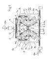
- FIGS. 1, 2 and 3 an inspection machine is shown in which four transport elements are provided, each formed as endless belts 2a, 2b, 2c, 2d.
- the four belts are arranged symmetrically both with respect to a support ring plane A and with respect to the plane spanned by the longitudinal axis of a preform and the transport direction, and in each case have the same angles ⁇ a, ⁇ b, ⁇ c, ⁇ d with respect to the support ring plane A.
- the circulation planes B1-B4 are substantially straight and run parallel to the carrier plate pairs 6a-6d. Between the legs of this X arrangement, there is sufficient space above and below the preform 1 for inspection units 12, 13, 14. With the aid of a camera 12, the mouth areas and possibly the injection points of the preforms are inspected by an imaging method.
- the preforms 1 are illuminated by means of a lamp 13 which is attached laterally and whose light is redirected to the preform 1 by means of a semipermeable mirror 14.
- the belts are 2c and 2d by tension rollers 7 in their clamping force adjust. But it is also possible to use all the belts Machine 2a-2e tighten by tension rollers 7.
- the the Belt 2a, 2b, 2c, 2d, 2e receiving drive wheels 4a ', 4a and the deflection rollers 4 are rotatable on carrier plates 6a-6d stored, in turn, on a base frame 8a-8d are mounted. For orientation, the base frame 8a-8d runs in profile rails 9.
- the two parts of the base frame 8c and 8d, and thus also the belt 2a attached thereto and 2b, are vertical by an adjusting device 10b adjustable, so that the vertical gap S 'between the upper support plate pair 6a, 6c and the lower Support plate pair 6b, 6d is variable.
- the Adjustment device 10b consists of a spindle and a crank. Upon actuation of the crank, the upper Support plate pair 6a and 6c with all attached thereto Elements such as belt 2a, 2b, or drive roller 4a 'to the Profile rails 11 moves along.
- this vertical gap S ' is during transport of preforms 1 of the support ring 1a.
- the setting of the vertical gap S ' is present because the Inspection machine at a grade change different Take preforms 1 with different bearing ring thicknesses 1a can.
- the adjustment of the vertical gap becomes S 'made so that it is a little smaller than that Tragringdicke 1a of the preform 1 to be transported to a frictional engagement of the belts 2a, 2b, 2c and 2d on To ensure support ring 1a.
- the horizontal gap S can with the help of a Adjustment device 10a, which also consists of a crank and a threaded spindle consists, to be adjusted.
- the left 6c, 6d and the right pair of carrier plates 6a, 6c preferably set so that the horizontal gap S between them is slightly smaller than the diameter of the too transporting preforms 1, here too to achieve frictional transport.
- the Adjustment 10a actuated so that the Base frame halves 8a, 8b horizontally across Transport direction apart or move towards each other to make the gap S larger or smaller.
- Both the gap width of the gap S and the gap S ' is in the preform inlet area of the inspection machine greater than in the further course of the inspection machine.
- the propeller shafts 5, the driving force from the engine 3 and the Drive roller 4a 'to the other drive rollers 4a transferred, are designed longitudinally adjustable. This is necessary, because at the horizontal and vertical Adjusting the belts (2a-2d) for the purpose of taking up various preforms 1 with different mouth and Tragringgeometrien, also the distances between the Change drive rollers 4a 'and 4a.
- the belts 2a, 2b, 2c and 2d are with a certain Geometry equipped as well as possible on the support ring 1a of Preforms 1 lie (see Fig. 3).
- the two lower ones Belt 2c and 2d are perpendicular to each other Surfaces on top with the preform 1 at the bottom of the Tragrings are engaged, where this also one right angle between the support ring plane A and its Longitudinal axis forms.
- the two upper belts 2a and 2b Run parallel on the side away from the preform 1 the support ring plane A and the lower belt 2c and 2d. On the the preform 1 side facing the belt 2a and 2b run at an angle between that of the support ring plane A and the corresponds to the upper part of the support ring.
- the insides of the Belt 2a-2d are designed as toothed belts. For the sake of clarity this is not shown here.
- the timing belt side of the Belt 2a-2d is made of HTD, while the applied, profiled side of Linatex ® exists.
- a Ejecting device 15 At the exit of the inspection machine is a Ejecting device 15, the defective or not more usable preforms 1 for further use in withdraws following machine cycle. It is is any commercially available ejection device 15, they are not detailed here for the sake of clarity is shown.
Landscapes
- Engineering & Computer Science (AREA)
- Mechanical Engineering (AREA)
- Manufacturing & Machinery (AREA)
- Biochemistry (AREA)
- General Physics & Mathematics (AREA)
- Life Sciences & Earth Sciences (AREA)
- Chemical & Material Sciences (AREA)
- Analytical Chemistry (AREA)
- Physics & Mathematics (AREA)
- General Health & Medical Sciences (AREA)
- Health & Medical Sciences (AREA)
- Immunology (AREA)
- Pathology (AREA)
- Blow-Moulding Or Thermoforming Of Plastics Or The Like (AREA)
- Investigating Materials By The Use Of Optical Means Adapted For Particular Applications (AREA)
- Structure Of Belt Conveyors (AREA)
- Separation Using Semi-Permeable Membranes (AREA)
Abstract
Description
In einer bevorzugten Ausführungsform ist der Spalt zwischen den oberen und unteren Transportelementen, in dem sich während des Transports des Preforms der Tragring befindet, kleiner als die Dicke des Tragrings, um den Transport reibschlüssig zu vollziehen. Der Spalt zwischen den beiden quer zur Längsachse des Preforms versetzten Transportelementpaaren, die den Preform am Tragring greifen, ist vorzugsweise kleiner als der Durchmesser des Preforms. Auf diese Weise wird auch bezüglich der Preformbreite ein reibschlüssiger Transport gewährleistet.
- Fig. 1:
- Vorderansicht einer Inspektionsmaschine,
- Fig. 2:
- Draufsicht auf eine Inspektionsmaschine und
- Fig. 3:
- Vorderansicht der mit dem Preform in Eingriff stehenden Riemen.
Zwischen den Schenkeln dieser X-Anordnung bietet sich über und unter dem Preform 1 jeweils genügend Platz für Inspektionseinheiten 12, 13, 14. Mit Hilfe einer Kamera 12 werden die Mündungsbereiche und gegebenenfalls die Anspritzpunkte der Preforms durch ein bildgebendes Verfahren inspiziert. Beleuchtet werden die Preforms 1 mit Hilfe einer oberhalb seitlich angebrachten Lampe 13, deren Licht mit Hilfe eines semipermeablen Spiegels 14 zum Preform 1 umgeleitet wird.
Claims (20)
- Inspektionsmaschine mit Inspektionseinheiten (12,13,14) zum Inspizieren von Hohlkörpern (1) die einen Tragring (1a) aufweisen und mit einer Vorrichtung zum Transportieren der Hohlkörper (1), bestehend aus mindestens drei die Hohlkörper (1) führenden Transportelementen (2a bis 2d), von denen mindestens eines antreibbar ist und in einer Umlaufebene (B1 bis B4) umläuft, dadurch gekennzeichnet, dass die mindestens eine Umlaufebene (B1 bis B4) an der vom Hohlkörper (1) wegweisenden Seite in einem Winkel (αa-αd) von größer 0° und kleiner 90° zu einer Tragringebene (A) angeordnet ist.
- Maschine nach Anspruch 1, dadurch gekennzeichnet, dass es sich bei dem mindestens einen antreibbaren Transportelement (2a bis 2d) um ein Endlostransportelement handelt.
- Maschine nach Anspruch 1 oder 2, dadurch gekennzeichnet, dass es sich bei dem mindestens einen antreibbaren Transportelement (2a bis 2d) um einen Riemen handelt.
- Maschine nach den Ansprüchen 1 bis 3, dadurch gekennzeichnet, dass das mindestens eine antreibbare Transportelement (2a bis 2d) an Umlenkrollen (4) und Antriebsrollen (4a,4a') anliegt.
- Maschine nach einem der vorhergehenden Ansprüche, dadurch gekennzeichnet, dass es sich bei mindestens zwei Transportelementen (2a bis 2d) um antreibbare Riemen handelt, die in jeweils einer eigenen Umlaufebene(B1 bis B4) umlaufen.
- Maschine nach Anspruch 5, dadurch gekennzeichnet, dass mindestens ein Transportelement (2a bis 2d) separat antreibbar ist.
- Maschine nach wenigstens einem der vorangegangenen Ansprüche 1 bis 6, dadurch gekennzeichnet, dass die Winkel (αa-αd) zwischen den Umlaufebenen (B1 bis B4) und der Tragringebene (A) gleich sind.
- Maschine nach wenigstens einem der vorangegangenen Ansprüche 1 bis 7, dadurch gekennzeichnet, dass die Winkel (αa bis αd) zwischen 20° und 80°, vorzugsweise zwischen 55° und 65° liegen.
- Maschine nach wenigstens einem der vorangegangenen Ansprüche, dadurch gekennzeichnet, dass vier Transportelemente (2a bis 2d) vorhanden sind, die in jeweils einer Umlaufebene umlaufen (B1 bis B4) und als Riemen ausgebildet sind.
- Maschine nach Anspruch 9, dadurch gekennzeichnet, dass die Riemen (2a bis 2d) jeweils paarweise an gegenüberliegenden Seiten oben und unten am Tragring (1a) angreifen.
- Maschine nach Anspruch 9 und 10, dadurch gekennzeichnet, dass mindestens ein Riemenpaar (2a,2b; 2c,2d), das oben und unten am Tragring (1a) angreift, vertikal verstellbar ist, um einen Spalt S', in dem sich beim Transport der Hohlkörper (1) der Tragring (1a) befindet, variieren zu können.
- Maschine nach Anspruch 11, dadurch gekennzeichnet, dass der Spalt S' kleiner als die Dicke des Tragrings (1a) der Hohlkörper (1) ist und die Riemen (2a bis 2d) somit reibschlüssig am Tragring (1a) angreifen.
- Maschine nach einem der vorhergehenden Ansprüche, dadurch gekennzeichnet, dass mindestens ein Riemenpaar (2a,2d; 2b,2c), das seitlich am Hohlkörper (1) angreift, quer zu einer Transportrichtung (T) verstellbar ist, um Hohlkörper (1) verschiedener Durchmesser aufnehmen zu können.
- Maschine nach den Ansprüchen 9 bis 13 dadurch gekennzeichnet, dass die Umlaufebenen (B1 bis B4)bezüglich der Transportrichtung (T) der Hohlkörper (1) so angeordnet sind, dass sie im Wesentlichen eine symmetrische X-Anordnung bilden.
- Maschine nach einem der vorhergehenden Ansprüche, dadurch gekennzeichnet, dass sich im oberen und/oder unteren Schenkelbereich der X-Anordnung mindestens eine Inspektionseinheit (12,13,14) zum Inspizieren der Hohlkörper (1) befindet.
- Maschine nach einem der vorhergehenden Ansprüche, dadurch gekennzeichnet, dass der Transport der Hohlkörper (1) im Wesentlichen linear und horizontal erfolgt.
- Maschine nach einem der vorhergehenden Ansprüche, dadurch gekennzeichnet, dass die Riemen (2a bis 2d) durch jeweils einen eigenen Motor (3) angetrieben werden.
- Maschine nach einem der vorhergehenden Ansprüche, dadurch gekennzeichnet, dass nur ein Riemen (2a) durch einen Motor (3) angetrieben wird, während der Antrieb der anderen Riemen (2b bis 2d) über Verbindungen (5) zum ersten erfolgt.
- Maschine nach einem der vorhergehenden Ansprüche, dadurch gekennzeichnet, dass nach der Transportstrecke durch die Inspektionsmaschine eine Auswerfvorrichtung (15) für nicht verwendbare Hohlköper (1) angeordnet ist.
- Maschine nach einem der vorangegangenen Ansprüche, dadurch gekennzeichnet, dass die Hohlkörper (1) Gefäße sind, insbesondere Flaschen aus Kunststoff oder Preforms zur Herstellung derselben.
Applications Claiming Priority (2)
| Application Number | Priority Date | Filing Date | Title |
|---|---|---|---|
| DE102004009698 | 2004-02-27 | ||
| DE102004009698A DE102004009698A1 (de) | 2004-02-27 | 2004-02-27 | Inspektionsmaschine mit einer Vorrichtung zum Transportieren von Hohlkörpern |
Publications (2)
| Publication Number | Publication Date |
|---|---|
| EP1568625A1 true EP1568625A1 (de) | 2005-08-31 |
| EP1568625B1 EP1568625B1 (de) | 2006-08-23 |
Family
ID=34745306
Family Applications (1)
| Application Number | Title | Priority Date | Filing Date |
|---|---|---|---|
| EP05003613A Expired - Lifetime EP1568625B1 (de) | 2004-02-27 | 2005-02-19 | Inspektionsmaschine mit einer Vorrichtung zum Transportieren von Hohlkörpern |
Country Status (3)
| Country | Link |
|---|---|
| EP (1) | EP1568625B1 (de) |
| AT (1) | ATE337241T1 (de) |
| DE (2) | DE102004009698A1 (de) |
Cited By (4)
| Publication number | Priority date | Publication date | Assignee | Title |
|---|---|---|---|---|
| WO2012001414A3 (en) * | 2010-06-29 | 2012-02-23 | Constar International Uk Ltd. | Inspection |
| JP2013237567A (ja) * | 2005-09-09 | 2013-11-28 | Sidel Participations Sas | 物体の搬送装置 |
| EP3564006B1 (de) | 2018-05-04 | 2020-10-14 | INTRAVIS Gesellschaft für Lieferungen und Leistungen von bildgebenden und bildverarbeitenden Anlagen und Verfahren mbH | Vorrichtung zum transport und prüfen von vorformlingen |
| IT201900010416A1 (it) * | 2019-06-28 | 2020-12-28 | Sacmi | Dispositivo di ispezione ottica di preforme |
Families Citing this family (1)
| Publication number | Priority date | Publication date | Assignee | Title |
|---|---|---|---|---|
| DE102005060814B4 (de) * | 2005-12-20 | 2014-12-31 | Krones Aktiengesellschaft | Vorrichtung und Verfahren zum Formblasen von Behältern |
Citations (5)
| Publication number | Priority date | Publication date | Assignee | Title |
|---|---|---|---|---|
| US4680463A (en) * | 1983-04-22 | 1987-07-14 | Hajime Industries Ltd. | Apparatus for checking containers |
| EP0466278A1 (de) * | 1990-07-12 | 1992-01-15 | Gerardus Smit | Förderanlage für Flaschen |
| US5553698A (en) * | 1994-12-28 | 1996-09-10 | J And J Container Handling Systems | Conveyor belt apparatus for bottles |
| EP0842875A1 (de) * | 1996-11-13 | 1998-05-20 | Simplimatic Engineering Company | Förderer für ausgerichtete Flaschen |
| JP2000168945A (ja) * | 1998-12-07 | 2000-06-20 | Kirin Techno System:Kk | プリフォーム検査用搬送装置 |
Family Cites Families (2)
| Publication number | Priority date | Publication date | Assignee | Title |
|---|---|---|---|---|
| DE3515353A1 (de) * | 1985-04-27 | 1986-10-30 | Seitz Enzinger Noll Maschinenbau Ag, 6800 Mannheim | Vorrichtung zum foerdern von flaschen in haengender lage |
| JP2001063807A (ja) * | 1999-08-31 | 2001-03-13 | Sakamoto Engineering:Kk | 搬送装置 |
-
2004
- 2004-02-27 DE DE102004009698A patent/DE102004009698A1/de not_active Withdrawn
-
2005
- 2005-02-19 AT AT05003613T patent/ATE337241T1/de active
- 2005-02-19 DE DE502005000061T patent/DE502005000061D1/de not_active Expired - Lifetime
- 2005-02-19 EP EP05003613A patent/EP1568625B1/de not_active Expired - Lifetime
Patent Citations (5)
| Publication number | Priority date | Publication date | Assignee | Title |
|---|---|---|---|---|
| US4680463A (en) * | 1983-04-22 | 1987-07-14 | Hajime Industries Ltd. | Apparatus for checking containers |
| EP0466278A1 (de) * | 1990-07-12 | 1992-01-15 | Gerardus Smit | Förderanlage für Flaschen |
| US5553698A (en) * | 1994-12-28 | 1996-09-10 | J And J Container Handling Systems | Conveyor belt apparatus for bottles |
| EP0842875A1 (de) * | 1996-11-13 | 1998-05-20 | Simplimatic Engineering Company | Förderer für ausgerichtete Flaschen |
| JP2000168945A (ja) * | 1998-12-07 | 2000-06-20 | Kirin Techno System:Kk | プリフォーム検査用搬送装置 |
Non-Patent Citations (1)
| Title |
|---|
| PATENT ABSTRACTS OF JAPAN vol. 2000, no. 09 13 October 2000 (2000-10-13) * |
Cited By (10)
| Publication number | Priority date | Publication date | Assignee | Title |
|---|---|---|---|---|
| JP2013237567A (ja) * | 2005-09-09 | 2013-11-28 | Sidel Participations Sas | 物体の搬送装置 |
| WO2012001414A3 (en) * | 2010-06-29 | 2012-02-23 | Constar International Uk Ltd. | Inspection |
| EP3564006B1 (de) | 2018-05-04 | 2020-10-14 | INTRAVIS Gesellschaft für Lieferungen und Leistungen von bildgebenden und bildverarbeitenden Anlagen und Verfahren mbH | Vorrichtung zum transport und prüfen von vorformlingen |
| IT201900010416A1 (it) * | 2019-06-28 | 2020-12-28 | Sacmi | Dispositivo di ispezione ottica di preforme |
| WO2020261193A1 (en) * | 2019-06-28 | 2020-12-30 | Sacmi Cooperativa Meccanici Imola Societa' Cooperativa | Device for optical inspection of preforms |
| CN114126832A (zh) * | 2019-06-28 | 2022-03-01 | 萨克米伊莫拉机械合作社合作公司 | 对型坯进行光学检查的装置 |
| JP2022538614A (ja) * | 2019-06-28 | 2022-09-05 | サクミ コオペラティヴァ メッカニチ イモラ ソシエタ コオペラティヴァ | プリフォームの光学検査のための装置 |
| US20220307989A1 (en) * | 2019-06-28 | 2022-09-29 | Sacmi Cooperativa Meccanici Imola Societa' Cooperativa | Device for optical inspection of preforms |
| CN114126832B (zh) * | 2019-06-28 | 2024-11-05 | 萨克米伊莫拉机械合作社合作公司 | 对型坯进行光学检查的装置 |
| US12158433B2 (en) * | 2019-06-28 | 2024-12-03 | Sacmi Cooperativa Meccanici Imola Societa′ Cooperativa | Device for optical inspection of preforms |
Also Published As
| Publication number | Publication date |
|---|---|
| DE502005000061D1 (de) | 2006-10-05 |
| ATE337241T1 (de) | 2006-09-15 |
| DE102004009698A1 (de) | 2005-09-15 |
| EP1568625B1 (de) | 2006-08-23 |
Similar Documents
| Publication | Publication Date | Title |
|---|---|---|
| EP1431021B1 (de) | Verfahren und Vorrichtung zum Herstellen von Hohlkörpern aus Kunststoff | |
| EP3635376B1 (de) | Vorrichtung und verfahren zum prüfen von hohlkörpern | |
| EP3678964B1 (de) | Vorrichtung und verfahren zur ausrichtung von gebinden | |
| EP0415154B2 (de) | Verfahren zum Inspizieren von Gegenständen aus unterschiedlichen Blickwinkeln | |
| DE60315138T3 (de) | Vorrichtung und Verfahren zur Qualitätsüberprüfung von Vorformlingen aus Kunststoff | |
| EP0996531B1 (de) | Vorrichtung und verfahren zur herstellung von kunststoffhohlkörpern | |
| EP2112502B1 (de) | Verfahren und Vorrichtung zur Prüfung von Behälter-Preforms | |
| DE69718374T2 (de) | Verfahren und Vorrichtung zum geordneten Abführen von ungeordnet zugeführten Produkten | |
| DE102012102073A1 (de) | Kontrollmodul | |
| DE102008017427B4 (de) | Vorrichtung sowie Verfahren zur Inspektion von Flaschen oder dergleichen Behältern | |
| DE2530886C3 (de) | Vorrichtung zum Ordnen vereinzelter, in entgegengesetzten Richtungen ungeordnet orientierter Gegenstände | |
| DE19737527C2 (de) | Vorrichtung zur Herstellung von Kunststoffhohlkörpern | |
| DE112017007612B4 (de) | Reifenfördervorrichtung, damit ausgestattetes Reifeninspektionssystem sowie Reifenförderverfahren | |
| EP1568625B1 (de) | Inspektionsmaschine mit einer Vorrichtung zum Transportieren von Hohlkörpern | |
| DE60317990T2 (de) | Vorrichtung zur Inspektion flacher Tabletten | |
| DE69426514T2 (de) | Anordnung zur Kontrolle von Hohlglasbehältern | |
| EP2802441A1 (de) | Holzbearbeitungsanlage und verfahren zu deren betrieb | |
| AT518335B1 (de) | Verfahren zum Prüfen eines, aus Druckfolien hergestellten, spritzgussgefertigten, Behälters | |
| DE202004021491U1 (de) | Inspektionsmaschine mit einer Vorrichtung zum Transportieren von Hohlkörpern | |
| DE4418359C2 (de) | Verfahren und Vorrichtung zum Ausrichten von Stückgut | |
| EP3577445B1 (de) | Inspektionsvorrichtung und -verfahren zur seitenwand- und verschlusskopfinspektion von behältern | |
| EP1271123A1 (de) | Verfahren und Vorrichtung zur Qualitätsprüfung elastischer und runder Formteile | |
| EP4548084B1 (de) | Prüfsystem | |
| EP3953261B1 (de) | Band-umreifungsmaschine zum umreifen eines umreifungsgutes mit einem band | |
| DE102023133768A1 (de) | Inspektionsvorrichtung für Behälter |
Legal Events
| Date | Code | Title | Description |
|---|---|---|---|
| PUAI | Public reference made under article 153(3) epc to a published international application that has entered the european phase |
Free format text: ORIGINAL CODE: 0009012 |
|
| AK | Designated contracting states |
Kind code of ref document: A1 Designated state(s): AT BE BG CH CY CZ DE DK EE ES FI FR GB GR HU IE IS IT LI LT LU MC NL PL PT RO SE SI SK TR |
|
| AX | Request for extension of the european patent |
Extension state: AL BA HR LV MK YU |
|
| 17P | Request for examination filed |
Effective date: 20050805 |
|
| GRAP | Despatch of communication of intention to grant a patent |
Free format text: ORIGINAL CODE: EPIDOSNIGR1 |
|
| AKX | Designation fees paid |
Designated state(s): AT BE BG CH CY CZ DE DK EE ES FI FR GB GR HU IE IS IT LI LT LU MC NL PL PT RO SE SI SK TR |
|
| GRAS | Grant fee paid |
Free format text: ORIGINAL CODE: EPIDOSNIGR3 |
|
| GRAA | (expected) grant |
Free format text: ORIGINAL CODE: 0009210 |
|
| AK | Designated contracting states |
Kind code of ref document: B1 Designated state(s): AT BE BG CH CY CZ DE DK EE ES FI FR GB GR HU IE IS IT LI LT LU MC NL PL PT RO SE SI SK TR |
|
| PG25 | Lapsed in a contracting state [announced via postgrant information from national office to epo] |
Ref country code: CZ Free format text: LAPSE BECAUSE OF FAILURE TO SUBMIT A TRANSLATION OF THE DESCRIPTION OR TO PAY THE FEE WITHIN THE PRESCRIBED TIME-LIMIT Effective date: 20060823 Ref country code: PL Free format text: LAPSE BECAUSE OF FAILURE TO SUBMIT A TRANSLATION OF THE DESCRIPTION OR TO PAY THE FEE WITHIN THE PRESCRIBED TIME-LIMIT Effective date: 20060823 Ref country code: LT Free format text: LAPSE BECAUSE OF FAILURE TO SUBMIT A TRANSLATION OF THE DESCRIPTION OR TO PAY THE FEE WITHIN THE PRESCRIBED TIME-LIMIT Effective date: 20060823 Ref country code: IT Free format text: LAPSE BECAUSE OF FAILURE TO SUBMIT A TRANSLATION OF THE DESCRIPTION OR TO PAY THE FEE WITHIN THE PRESCRIBED TIME-LIMIT;WARNING: LAPSES OF ITALIAN PATENTS WITH EFFECTIVE DATE BEFORE 2007 MAY HAVE OCCURRED AT ANY TIME BEFORE 2007. THE CORRECT EFFECTIVE DATE MAY BE DIFFERENT FROM THE ONE RECORDED. Effective date: 20060823 Ref country code: IE Free format text: LAPSE BECAUSE OF FAILURE TO SUBMIT A TRANSLATION OF THE DESCRIPTION OR TO PAY THE FEE WITHIN THE PRESCRIBED TIME-LIMIT Effective date: 20060823 Ref country code: RO Free format text: LAPSE BECAUSE OF FAILURE TO SUBMIT A TRANSLATION OF THE DESCRIPTION OR TO PAY THE FEE WITHIN THE PRESCRIBED TIME-LIMIT Effective date: 20060823 Ref country code: IS Free format text: LAPSE BECAUSE OF FAILURE TO SUBMIT A TRANSLATION OF THE DESCRIPTION OR TO PAY THE FEE WITHIN THE PRESCRIBED TIME-LIMIT Effective date: 20060823 Ref country code: SI Free format text: LAPSE BECAUSE OF FAILURE TO SUBMIT A TRANSLATION OF THE DESCRIPTION OR TO PAY THE FEE WITHIN THE PRESCRIBED TIME-LIMIT Effective date: 20060823 Ref country code: NL Free format text: LAPSE BECAUSE OF FAILURE TO SUBMIT A TRANSLATION OF THE DESCRIPTION OR TO PAY THE FEE WITHIN THE PRESCRIBED TIME-LIMIT Effective date: 20060823 Ref country code: SK Free format text: LAPSE BECAUSE OF FAILURE TO SUBMIT A TRANSLATION OF THE DESCRIPTION OR TO PAY THE FEE WITHIN THE PRESCRIBED TIME-LIMIT Effective date: 20060823 Ref country code: FI Free format text: LAPSE BECAUSE OF FAILURE TO SUBMIT A TRANSLATION OF THE DESCRIPTION OR TO PAY THE FEE WITHIN THE PRESCRIBED TIME-LIMIT Effective date: 20060823 |
|
| REG | Reference to a national code |
Ref country code: GB Ref legal event code: FG4D Free format text: NOT ENGLISH |
|
| REG | Reference to a national code |
Ref country code: CH Ref legal event code: NV Representative=s name: PATENTANWALTSBUERO JEAN HUNZIKER Ref country code: CH Ref legal event code: EP |
|
| REG | Reference to a national code |
Ref country code: IE Ref legal event code: FG4D Free format text: LANGUAGE OF EP DOCUMENT: GERMAN |
|
| REF | Corresponds to: |
Ref document number: 502005000061 Country of ref document: DE Date of ref document: 20061005 Kind code of ref document: P |
|
| GBT | Gb: translation of ep patent filed (gb section 77(6)(a)/1977) |
Effective date: 20061018 |
|
| PG25 | Lapsed in a contracting state [announced via postgrant information from national office to epo] |
Ref country code: SE Free format text: LAPSE BECAUSE OF FAILURE TO SUBMIT A TRANSLATION OF THE DESCRIPTION OR TO PAY THE FEE WITHIN THE PRESCRIBED TIME-LIMIT Effective date: 20061123 Ref country code: BG Free format text: LAPSE BECAUSE OF FAILURE TO SUBMIT A TRANSLATION OF THE DESCRIPTION OR TO PAY THE FEE WITHIN THE PRESCRIBED TIME-LIMIT Effective date: 20061123 Ref country code: DK Free format text: LAPSE BECAUSE OF FAILURE TO SUBMIT A TRANSLATION OF THE DESCRIPTION OR TO PAY THE FEE WITHIN THE PRESCRIBED TIME-LIMIT Effective date: 20061123 |
|
| PG25 | Lapsed in a contracting state [announced via postgrant information from national office to epo] |
Ref country code: ES Free format text: LAPSE BECAUSE OF FAILURE TO SUBMIT A TRANSLATION OF THE DESCRIPTION OR TO PAY THE FEE WITHIN THE PRESCRIBED TIME-LIMIT Effective date: 20061204 |
|
| PG25 | Lapsed in a contracting state [announced via postgrant information from national office to epo] |
Ref country code: PT Free format text: LAPSE BECAUSE OF FAILURE TO SUBMIT A TRANSLATION OF THE DESCRIPTION OR TO PAY THE FEE WITHIN THE PRESCRIBED TIME-LIMIT Effective date: 20070125 |
|
| NLV1 | Nl: lapsed or annulled due to failure to fulfill the requirements of art. 29p and 29m of the patents act | ||
| ET | Fr: translation filed | ||
| PG25 | Lapsed in a contracting state [announced via postgrant information from national office to epo] |
Ref country code: MC Free format text: LAPSE BECAUSE OF NON-PAYMENT OF DUE FEES Effective date: 20070228 |
|
| REG | Reference to a national code |
Ref country code: IE Ref legal event code: FD4D |
|
| PLBE | No opposition filed within time limit |
Free format text: ORIGINAL CODE: 0009261 |
|
| STAA | Information on the status of an ep patent application or granted ep patent |
Free format text: STATUS: NO OPPOSITION FILED WITHIN TIME LIMIT |
|
| 26N | No opposition filed |
Effective date: 20070524 |
|
| BERE | Be: lapsed |
Owner name: KRONES A.G. Effective date: 20070228 |
|
| PG25 | Lapsed in a contracting state [announced via postgrant information from national office to epo] |
Ref country code: BE Free format text: LAPSE BECAUSE OF NON-PAYMENT OF DUE FEES Effective date: 20070228 |
|
| PG25 | Lapsed in a contracting state [announced via postgrant information from national office to epo] |
Ref country code: GR Free format text: LAPSE BECAUSE OF FAILURE TO SUBMIT A TRANSLATION OF THE DESCRIPTION OR TO PAY THE FEE WITHIN THE PRESCRIBED TIME-LIMIT Effective date: 20061124 |
|
| PG25 | Lapsed in a contracting state [announced via postgrant information from national office to epo] |
Ref country code: EE Free format text: LAPSE BECAUSE OF FAILURE TO SUBMIT A TRANSLATION OF THE DESCRIPTION OR TO PAY THE FEE WITHIN THE PRESCRIBED TIME-LIMIT Effective date: 20060823 |
|
| PGRI | Patent reinstated in contracting state [announced from national office to epo] |
Ref country code: IT Effective date: 20090401 |
|
| PG25 | Lapsed in a contracting state [announced via postgrant information from national office to epo] |
Ref country code: CY Free format text: LAPSE BECAUSE OF FAILURE TO SUBMIT A TRANSLATION OF THE DESCRIPTION OR TO PAY THE FEE WITHIN THE PRESCRIBED TIME-LIMIT Effective date: 20060823 Ref country code: LU Free format text: LAPSE BECAUSE OF NON-PAYMENT OF DUE FEES Effective date: 20070219 |
|
| PG25 | Lapsed in a contracting state [announced via postgrant information from national office to epo] |
Ref country code: HU Free format text: LAPSE BECAUSE OF FAILURE TO SUBMIT A TRANSLATION OF THE DESCRIPTION OR TO PAY THE FEE WITHIN THE PRESCRIBED TIME-LIMIT Effective date: 20070224 Ref country code: TR Free format text: LAPSE BECAUSE OF FAILURE TO SUBMIT A TRANSLATION OF THE DESCRIPTION OR TO PAY THE FEE WITHIN THE PRESCRIBED TIME-LIMIT Effective date: 20060823 |
|
| PGFP | Annual fee paid to national office [announced via postgrant information from national office to epo] |
Ref country code: CH Payment date: 20120214 Year of fee payment: 8 |
|
| PGFP | Annual fee paid to national office [announced via postgrant information from national office to epo] |
Ref country code: GB Payment date: 20120215 Year of fee payment: 8 |
|
| PGFP | Annual fee paid to national office [announced via postgrant information from national office to epo] |
Ref country code: AT Payment date: 20120126 Year of fee payment: 8 |
|
| REG | Reference to a national code |
Ref country code: CH Ref legal event code: PL |
|
| REG | Reference to a national code |
Ref country code: AT Ref legal event code: MM01 Ref document number: 337241 Country of ref document: AT Kind code of ref document: T Effective date: 20130228 |
|
| GBPC | Gb: european patent ceased through non-payment of renewal fee |
Effective date: 20130219 |
|
| PG25 | Lapsed in a contracting state [announced via postgrant information from national office to epo] |
Ref country code: LI Free format text: LAPSE BECAUSE OF NON-PAYMENT OF DUE FEES Effective date: 20130228 Ref country code: CH Free format text: LAPSE BECAUSE OF NON-PAYMENT OF DUE FEES Effective date: 20130228 Ref country code: AT Free format text: LAPSE BECAUSE OF NON-PAYMENT OF DUE FEES Effective date: 20130228 |
|
| PG25 | Lapsed in a contracting state [announced via postgrant information from national office to epo] |
Ref country code: GB Free format text: LAPSE BECAUSE OF NON-PAYMENT OF DUE FEES Effective date: 20130219 |
|
| REG | Reference to a national code |
Ref country code: FR Ref legal event code: PLFP Year of fee payment: 11 |
|
| PGFP | Annual fee paid to national office [announced via postgrant information from national office to epo] |
Ref country code: IT Payment date: 20150216 Year of fee payment: 11 Ref country code: DE Payment date: 20150210 Year of fee payment: 11 |
|
| PGFP | Annual fee paid to national office [announced via postgrant information from national office to epo] |
Ref country code: FR Payment date: 20150210 Year of fee payment: 11 |
|
| REG | Reference to a national code |
Ref country code: DE Ref legal event code: R119 Ref document number: 502005000061 Country of ref document: DE |
|
| REG | Reference to a national code |
Ref country code: FR Ref legal event code: ST Effective date: 20161028 |
|
| PG25 | Lapsed in a contracting state [announced via postgrant information from national office to epo] |
Ref country code: IT Free format text: LAPSE BECAUSE OF FAILURE TO SUBMIT A TRANSLATION OF THE DESCRIPTION OR TO PAY THE FEE WITHIN THE PRESCRIBED TIME-LIMIT Effective date: 20160219 |
|
| PG25 | Lapsed in a contracting state [announced via postgrant information from national office to epo] |
Ref country code: FR Free format text: LAPSE BECAUSE OF NON-PAYMENT OF DUE FEES Effective date: 20160229 Ref country code: DE Free format text: LAPSE BECAUSE OF NON-PAYMENT OF DUE FEES Effective date: 20160901 |