EP3953261B1 - Band-umreifungsmaschine zum umreifen eines umreifungsgutes mit einem band - Google Patents
Band-umreifungsmaschine zum umreifen eines umreifungsgutes mit einem band Download PDFInfo
- Publication number
- EP3953261B1 EP3953261B1 EP20711144.4A EP20711144A EP3953261B1 EP 3953261 B1 EP3953261 B1 EP 3953261B1 EP 20711144 A EP20711144 A EP 20711144A EP 3953261 B1 EP3953261 B1 EP 3953261B1
- Authority
- EP
- European Patent Office
- Prior art keywords
- strapping
- camera
- machine
- bundle
- strapping machine
- Prior art date
- Legal status (The legal status is an assumption and is not a legal conclusion. Google has not performed a legal analysis and makes no representation as to the accuracy of the status listed.)
- Active
Links
Images

Classifications
-
- B—PERFORMING OPERATIONS; TRANSPORTING
- B65—CONVEYING; PACKING; STORING; HANDLING THIN OR FILAMENTARY MATERIAL
- B65B—MACHINES, APPARATUS OR DEVICES FOR, OR METHODS OF, PACKAGING ARTICLES OR MATERIALS; UNPACKING
- B65B13/00—Bundling articles
- B65B13/02—Applying and securing binding material around articles or groups of articles, e.g. using strings, wires, strips, bands or tapes
- B65B13/04—Applying and securing binding material around articles or groups of articles, e.g. using strings, wires, strips, bands or tapes with means for guiding the binding material around the articles prior to severing from supply
- B65B13/06—Stationary ducts or channels
-
- B—PERFORMING OPERATIONS; TRANSPORTING
- B65—CONVEYING; PACKING; STORING; HANDLING THIN OR FILAMENTARY MATERIAL
- B65B—MACHINES, APPARATUS OR DEVICES FOR, OR METHODS OF, PACKAGING ARTICLES OR MATERIALS; UNPACKING
- B65B13/00—Bundling articles
- B65B13/18—Details of, or auxiliary devices used in, bundling machines or bundling tools
-
- B—PERFORMING OPERATIONS; TRANSPORTING
- B65—CONVEYING; PACKING; STORING; HANDLING THIN OR FILAMENTARY MATERIAL
- B65B—MACHINES, APPARATUS OR DEVICES FOR, OR METHODS OF, PACKAGING ARTICLES OR MATERIALS; UNPACKING
- B65B27/00—Bundling particular articles presenting special problems using string, wire, or narrow tape or band; Baling fibrous material, e.g. peat, not otherwise provided for
- B65B27/08—Bundling paper sheets, envelopes, bags, newspapers, or other thin flat articles
-
- B—PERFORMING OPERATIONS; TRANSPORTING
- B65—CONVEYING; PACKING; STORING; HANDLING THIN OR FILAMENTARY MATERIAL
- B65B—MACHINES, APPARATUS OR DEVICES FOR, OR METHODS OF, PACKAGING ARTICLES OR MATERIALS; UNPACKING
- B65B57/00—Automatic control, checking, warning, or safety devices
-
- B—PERFORMING OPERATIONS; TRANSPORTING
- B65—CONVEYING; PACKING; STORING; HANDLING THIN OR FILAMENTARY MATERIAL
- B65B—MACHINES, APPARATUS OR DEVICES FOR, OR METHODS OF, PACKAGING ARTICLES OR MATERIALS; UNPACKING
- B65B59/00—Arrangements to enable machines to handle articles of different sizes, to produce packages of different sizes, to vary the contents of packages, to handle different types of packaging material, or to give access for cleaning or maintenance purposes
- B65B59/02—Arrangements to enable adjustments to be made while the machine is running
Definitions
- the invention relates to a strapping machine for strapping a strapping item with a strapping band, which is preferably a weldable plastic band, with the features specified in the preamble of patent claim 1.
- strapped goods is understood in the context of the invention to mean that it includes various, mostly similar goods that are combined into an easily manageable bundle using one or more strapping bands.
- a typical example of a Strapping material is a stack of folding box blanks. Since the individual folding box blanks are difficult to handle and transport without strapping, they are bundled into a bundle using a strapping band.
- a strapping machine comprises a machine table that supports the strapping material during strapping and at least one strapping device.
- Such strapping machines are known, for example, from WO 2012/152626 A2 , the CH 704 537 A2 or the DE 198 21 918 A1 known.
- a modular handling unit is known that can be configured as a removal module, buffer module, corner transfer module or strapping unit. Depending on the desired function, the handling unit is equipped with drives, light barriers, etc.
- the state-of-the-art strapping machines work very reliably and are very efficient. They are usually located at the end of a longer process chain. If everything in this process chain goes as planned, then the strapping machine only contains flawless strapping goods, which are then bundled into a bundle using one or more strapping bands.
- the entire bundle must be removed from the production process, the bundle must be opened and the defective folding box blank replaced with a faultless one.
- the stack of folding box blanks can then be fed back into the strapping machine and bundled into a bundle.
- the quality control of the bundles is carried out after the strapping machine. If a bundle is detected there that contains one or more faulty folding box blanks or other faulty strapping material ("faulty bundle"), it is removed from the production process in a downstream ejection station and sent for further processing.
- faulty bundle faulty folding box blanks or other faulty strapping material
- the DE 10 2017 102 854 B3 describes a bundling device with a permanently installed camera underneath a table or a camera attached to a press beam, which captures the side edges of a bundled product.
- a similar configuration is also known from the DE 10 2008 031 236 A1 known.
- JP 200255512 A shows a strapping device with a fixed camera.
- the invention is based on the object of improving the functionality of a strapping machine and of making the overall space requirement of a process chain, which includes, among other things, the steps of strapping a strapping item into a bundle, quality control and ejecting faulty bundles, more economical, space-saving and reliable.
- a camera in the strapping machine is directed at the strapping material at least temporarily, errors in the strapping material can be detected and a bundle identified as faulty, which contains a faulty product/a faulty folding box blank, can be removed directly in the strapping machine be eliminated from the process chain.
- the camera installed in the strapping machine according to the invention can detect all defects in the products or folding box blanks that can be detected visually. If a defect is detected, the bundle with the defective product/folding box blank can be removed from the process chain. It is irrelevant where in the upstream process chain the defect occurred. This makes the quality control according to the invention very effective and the rate of detected defects is high. Conversely, this means that almost no bundles with defective products or defective folding box blanks reach the end of the process chain and then to the customer undetected.
- the camera can be moved in a direction that is orthogonal to a plane spanned by the machine table.
- the movement device for example in the form of a ball screw guide, makes it possible to "travel" the front, the back and/or one side of the bundle with the camera and to take pictures of the corresponding side of the bundle.
- suitable image analysis faulty bundles can be identified and the faulty bundles can be ejected.
- the camera can be moved in the direction of a Z-axis (i.e. orthogonal to the X-Y plane spanned by the machine table). This makes it possible to move the camera out of the direction of movement or conveying direction (X-axis) of the bundle as soon as the bundle is to be conveyed out of the strapping machine.
- the camera's ability to move also makes it easy to adapt the strapping machine according to the invention to product stacks of different sizes. Further flexibility is achieved if the camera can be moved in a second axis (Y-axis), which preferably extends orthogonally to the first axis of movement. Then, for example, the entire front or back of a bundle can be captured by the camera, even if it can only take pictures of part of the bundle. It is also possible to specifically target individual spots on the front, back or sides of the bundle. This means that the points on the bundle where errors are expected can be targeted and captured by the camera. The rest of the surfaces of the bundle do not then have to be captured by the camera.
- Y-axis second axis
- the strapping material is a stack of several folding box blanks
- the columns of the folding box blanks in the bundle are arranged one above the other.
- the columns of the folding box blanks are arranged along a vertical line (Z-axis).
- the camera is positioned so that it is Movement in the direction of the Z-axis travels through all the gaps of the product stack and takes pictures of the gaps.
- gaps that are too wide or too narrow can be identified. Whenever a gap is identified that lies outside the specified tolerance range, the folding box blank is faulty and the faulty bundle is rejected.
- the term "camera" is very broad in the context of the invention. All image recording devices known from the state of the art can be used as cameras.
- CCD sensors matrix cameras, line cameras or laser triangulation sensors are preferred. It is important that properties of the bundle, in particular parts or the entire surface of the bundle, can be visually recorded by the camera.
- the images obtained are evaluated using an algorithm that can make a statement about whether the products in the product stack are faulty or fault-free. This evaluation can be carried out in a control unit of the strapping machine or a separate processor. If a faulty bundle is detected, a signal is issued which causes this bundle to be rejected.
- the strapping machine has a console arranged above the machine table, at least one press beam arranged movably on the console and at least one Manipulator for redirecting the strapping band, with a movement axis of the manipulator running orthogonal to a plane spanned by the machine table.
- the manipulator is therefore part of the band strapping machine.
- the movement direction of the manipulator and the camera run parallel (in the direction of the Z axis). It is therefore particularly advantageous if the camera or the device for optically capturing the product stack is attached directly or indirectly to the manipulator.
- the camera can then take pictures of the product stack/bundle in parallel to the actual function of the manipulator and at the same time. As soon as the product stack has been bundled into a bundle with a strapping band, it is already clear whether the bundle contains a defective product or not.
- the double use of the manipulator saves costs and installation space.
- the machine table and the console are connected to one another by one or more supports, wherein the distances between the supports in a conveying direction (X-axis) of the strapping material are greater than the length of the strapping material.
- a feeding device for transporting the strapping material to the machine table is arranged upstream of the machine table and/or that a removal device for transporting the strapping material away is arranged downstream of the machine table.
- strapping material from the machine table is arranged in the conveying direction. This ensures that the strapping material can be conveyed into the machine according to the invention and can also be removed from the strapping machine again after strapping.
- Constellations are also conceivable in which, for example, the device arranged in the process chain immediately before the strapping machine takes over the transport of the strapped goods into the strapping machine. In this case, a separate feed device or one assigned to the strapping machine can be omitted.
- this device can transport the bundle away from the strapping machine, a separate device assigned to the strapping machine for transporting it away from the strapping machine is not required.
- an ejection station is integrated in the strapping machine, which can transport a faulty bundle out of the strapping machine in an ejection direction that deviates from the normal transport direction (X-axis) (e.g. in the direction of the Y-axis).
- the machine table and the console are connected to one another by one or more supports and the distance between the supports in the conveying direction (X-axis) of the strapping material is greater than the length of the strapping material. It is then possible to eject a faulty strapping material from the side between the supports from the strapping machine, so that a faulty bundle can be ejected without requiring additional space.
- the ejection device can be designed in a simple and very effective variant as a pusher that is driven pneumatically, electromechanically or hydraulically. As soon as a faulty product stack is detected, the pusher is activated and pushes the product stack sideways out of the strapping machine between the supports that connect the machine table and the console.
- the discharge device into the machine table. It is particularly advantageous if the surface of the machine table is protected by a Ball grid conveyor belt.
- a Ball grid conveyor belt is sold by the company Ammeraal Beltec Holding BV in the Netherlands under the name "uniQNB Ball”. It has the property that the conveying direction of this ball grid conveyor belt can be controlled by the machine control system. If a product stack has been classified as "good”, the ball grid conveyor belt conveys the product stack in the conveying direction (X-axis) out of the strapping machine.
- the ball grid conveyor belt changes the conveying direction by 90° and ejects the product stack identified as faulty laterally out of the strapping machine in the direction of the Y-axis.
- the strapping machine according to the invention can be a longitudinal strapping machine.
- the camera according to the invention can use any technology known and suitable from the prior art.
- these devices can be a matrix camera, a line camera or a laser distance sensor. If in a preferred embodiment the camera is a laser distance sensor, then this laser distance sensor can work according to the principle of triangulation or the principle of the time of flight of light. Both modes of operation are suitable for detecting the shape, contour and position of grooves as well as for detecting the width of gaps.
- the costs of the strapping machine according to the invention with the integrated functionalities are significantly lower than if these three functionalities were implemented in three separate devices.
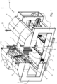
- FIG. 1 is an isometric view of an embodiment of a strapping machine according to the invention.
- the three spatial directions are shown in the form of a Cartesian coordinate system with the axes X, Y and Z.
- the direction of the X axis corresponds to the conveying direction of the strapped goods through the strapping machine.
- the strapping material 3 enters the machine from the rear and leaves it at the front end if the strapping material is free of defects. If a defect in the strapping material is detected in the strapping machine according to the invention, the product stack with the defective product is ejected from the side, ie in the direction of the positive Y-axis, from the strapping machine.
- the strapping machine comprises a machine frame 1 on which a machine table is arranged for receiving the strapping material 3.
- the machine table comprises two conveyor belts 10 which run parallel to each other and are able to To transport strapping material 3 in the conveying direction through the strapping machine.
- the strapping machine comprises several supports 4, of which in the Figure 1 only three are visible. Two supports 4 each carry a console 5. A press beam 6 is arranged on each of the consoles 5. The press beam 6 is used to press the strapping material 3, here a stack of folding box blanks, together before the strapping devices integrated into the consoles 5 place a strapping band around the strapping material 3 and this strapping band is then welded in a welding device 7 to form a closed band.
- the press beams 6 are connected to the consoles 5 via linear drives 9.
- the linear drives 9 can be designed as ball screws or as pneumatic cylinders. In any case, it is necessary that a sufficiently large force can be exerted on the strapping material using the linear drives 9. If, for example, the strapping material consists of folding box blanks stacked on top of one another, these will be pressed together by the press beams before they are bundled into a bundle with the strapping band.
- the strapping machine With the strapping machine according to the invention, it is possible to eject a bundle that has been identified as faulty laterally, i.e. in the direction of the positive Y axis. For this reason, the distance between the supports 4 in the direction of the X axis is greater than the length of the strapped goods.
- This design is very space-saving and enables the integration of the functions of an ejection station into the strapping machine without requiring additional space.
- the ejection can be carried out, for example, by Figure 1 left side of the machine table or the conveyor belts 10 there is a slider (not shown) which is operated pneumatically, electromechanically or hydraulically when a faulty bundle has to be ejected to the side.
- a slider (not shown) which is operated pneumatically, electromechanically or hydraulically when a faulty bundle has to be ejected to the side.
- the slider remains deactivated and the conveyor belts 10 take over the transport of the strapping material 3 through the strapping machine 1 in the direction of the X-axis.
- a strapping machine in this case a longitudinal strapping machine, is well known to the person skilled in the art, so that a detailed description of it is omitted.
- a camera 11 or another optical sensor is arranged on a linear guide 13.
- the linear guide 13 can be designed as a ball screw drive or as a pneumatically operated Linear guides can be used.
- the requirements for the linear guide 13 in terms of precision and speed are relatively low.
- the camera 11 can be moved in the direction of the Z axis in front of the front of the strapping material 3 from top to bottom or from bottom to top using the linear guide 13, so that either the entire front of the strapping material 3 or only a selected area of the strapping material 3 is captured by the camera 11. The same applies if the back or the sides of the strapping material 3 are to be captured by the camera.
- one or two optional light sources are aligned in such a way that they illuminate the image section captured by the camera 11 with sufficient brightness.
- the light sources 15, the camera 11 and the linear guide 13 are shown enlarged and more clearly.
- the optical sensor 11 and the light sources 15 are attached to the linear guide 13 with a carrier so that the light sources 15 and the camera 11 always assume the same relative positions to one another.
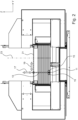
- FIG 2 is a front view of the strapping machine according to the invention.
- the camera 11 with the light sources 15 can be clearly seen. It can also be seen that the camera 11 is arranged at the lower end of the movable part of the linear guide 13. If the camera 11 is moved far enough upwards in the direction of the Z-axis, the camera 11 and the light sources 15 no longer hinder the removal of the bundle from the strapping machine according to the invention.
- the camera 11 and the light source 15 are in the way of the removal of the strapping material 3. It is therefore important that the camera 9 and the light sources 15 can be moved upwards.
- This first direction of movement (parallel to the Z axis) is indicated by a double arrow 17.
- the linear guide 13 is movably mounted on a second linear guide 21.
- the direction of movement of the second linear guide 21 is indicated by a double arrow 19. This means that by controlling the first linear guide 13 and the second linear guide 21, the camera 11 can visually capture every point on the front or back of the strapping material 3 or a bundle.
- the strapping material 3 is a stack of folding box blanks that have a gap. This gap is in the Figure 2 indicated by a small square black area. These columns are arranged in a row in the direction of the Z-axis when several folding box blanks are stacked on top of each other. The central axis of this row is shown as a dotted line 23 in the Figure 2 shown. From For reasons of clarity, the small black areas in the extension of the dash-dotted line 23, which represent the column, are not provided with reference symbols.
- the width of the gap can be determined and any faulty gaps (too large or too small) can be identified.
- any faulty folding box blank is identified in a bundle of folding box blanks, the bundle is ejected to the side and replaced outside of the regular folding box blank process chain.
- FIG 3 is a side view between two supports 4 onto the strapping material 3 and the first Linear guide 13 and the camera 11 are shown.
- the second linear guide 21 is covered by the press beam 6 in this view.
- the second linear guide 21 is screwed at its ends to one of the two press beams 6 or connected in some other way.
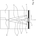
- the Figure 4 shows a detail of a view from above of the arrangement according to the invention.
- the first linear guide 13 with the camera 11 arranged thereon and the light sources 15 can be clearly seen.
- the light cones of the light sources 15 are indicated by lines 24.
- the image section of the camera 11 is indicated by lines 25.
- the strapping material namely folding box blanks
- the folding box blanks have a glue point 27 and a (lead) gap 29.
- the gap 29 is formed by the two edges of the folding box blank that was glued in the area of the glue point 27. If the glue point 27 is faulty, then the gap 29 is either too wide or too narrow. In many cases, both are intolerable, so that the folding box blank has to be sorted out.
- the width of the gap 29 is indicated by the black rectangular areas in the extension of the dot-dash line 23 in the Figure 2 shown.
Landscapes
- Engineering & Computer Science (AREA)
- Mechanical Engineering (AREA)
- Basic Packing Technique (AREA)
Description
- Die Erfindung betrifft eine Band-Umreifungsmaschine zum Umreifen eines Umreifungsgutes mit einem Umreifungsband, das bevorzugt ein verschweißbares Kunststoffband ist, mit den in Oberbegriff des Patentanspruchs 1 angegebenen Merkmalen.
- Der Begriff "Umreifungsgut" wird im Zusammenhang mit der Erfindung dahingehend verstanden, dass es verschiedene, meist gleichartige Güter umfasst, die mit Hilfe eines oder mehrerer Umreifungsbänder zu einem gut handhabbaren Bündel zusammengefasst werden. Ein typisches Beispiel für ein Umreifungsgut ist ein Stapel von Faltschachtelzuschnitten. Da die einzelnen Faltschachtelzuschnitte ohne Umreifung nur schlecht handhabbar und transportierbar sind, werden sie mit Hilfe eines Umreifungsbands zu einem Bündel gebündelt.
- Eine Band-Umreifungsmaschine umfasst einen Maschinentisch, der das Umreifungsgut während der Umreifung trägt, und mindestens eine Umreifungseinrichtung. Solche Umreifungsmaschinen sind beispielsweise aus der
WO 2012/152626 A2 , derCH 704 537 A2 DE 198 21 918 A1 bekannt. Aus derDE 198 21 918 A1 ist eine modular aufgebaute Handhabungseinheit bekannt, die wahlweise als Entnahmemodul, Puffermodul, Eckumsetzmodul oder Umreifungseinheit konfiguriert werden kann. Entsprechend der gewünschten Funktion wird die Handhabungseinheit mit Antrieben, Lichtschranken, etc. ausgerüstet. - Die aus dem Stand der Technik bekannten Band-Umreifungsmaschinen arbeiten sehr zuverlässig und sind sehr leistungsfähig. Sie sind zumeist am hinteren Ende einer längeren Prozesskette angeordnet. Wenn in dieser Prozesskette alles den gewünschten Gang geht, dann befinden sich in der Band-Umreifungsmaschine nur fehlerfreie Umreifungsgüter, die dort mit Hilfe von einem oder mehreren Umreifungsbändern zu einem Bündel gebündelt werden.
- Wenn in einem Bündel von beispielsweise 50 Faltschachtelzuschnitten nur ein einziger, nicht einwandfreier Faltschachtelzuschnitt vorhanden ist, muss das gesamte Bündel aus dem Produktionsprozess ausgeschleust werden, das Bündel muss geöffnet werden und der schadhafte Faltschachtelzuschnitt durch einen fehlerfreien ersetzt werden. Anschließend kann der Stapel von Faltschachtelzuschnitten erneut in die BandUmreifungsmaschine eingeschleust werden und zu einem Bündel gebündelt werden.
- Um zu gewährleisten, dass nur Bündel mit einwandfreien Faltschachtelzuschnitten zum Kunden gelangen, besteht die Notwendigkeit, in Echtzeit jedes Bündel nach dem Umreifen einer 100%ige Qualitätskontrolle zu unterziehen, so dass nur Bündel mit einwandfreien Produkten in der Prozesskette weiterbearbeitet werden und jedes Bündel, das einen fehlerhaften Faltschachtelzuschnitt oder ein anderes fehlerhaftes Produkt enthält, ausgeschleust und einer gesonderten Nachbearbeitung zugeführt wird.
- In der Regel wird die Qualitätskontrolle der Bündel im Anschluss an die Band-Umreifungsmaschine durchgeführt. Wenn dort ein Bündel erkannt wird, das einen oder mehrere fehlerhafte Faltschachtelzuschnitte oder ein anderes fehlerhaftes Umreifungsgut enthält ("fehlerhaftes Bündel"), wird es in einer nachgeschalteten Ausschleus-Station aus dem Produktionsprozess ausgeschleust und einer Nachbearbeitung zugeführt.
- In Summe sind also für das Umreifen, die Qualitätskontrolle und das Ausschleusen drei hintereinander angeordnete Stationen erforderlich. Um die Bündel durch diese Stationen zu befördern, sind Transporteinrichtungen, wie z.B. Förderbänder, notwendig. Diese Konfiguration benötigt sehr viel Platz, ist teuer und wegen der Verkettung auch störanfällig.
- Die
DE 10 2017 102 854 B3 beschreibt Bündelvorrichtung mit einer fest eingebauten Kamera unterhalb eines Tisches oder einer an einem Pressbalken angebrachten Kamera, welche die Seitenränder eines Bündelungsguts erfasst. Eine ähnliche Konfiguration ist auch aus derDE 10 2008 031 236 A1 bekannt. - Die
DE 20 2009 017 138 U1 und dieDE 10 2014 103 336 A1 beschreiben Vorrichtungen zum Längsumreifen mit einer optischen Einrichtung, die von oben die Kontur des Umreifungsguts erfasst. Auch dieJP 200255512 A - Der Erfindung liegt die Aufgabe zugrunde, eine BandUmreifungsmaschine in ihrer Funktionalität zu ertüchtigen und den Gesamtplatzbedarf einer Prozesskette, welche unter anderem die Schritte Umreifen eines Umreifungsgutes zu einem Bündel, Qualitätskontrolle und Ausschleusen fehlerhafter Bündel umfasst, wirtschaftlicher, platzsparender und zuverlässiger zu gestalten.
- Diese Aufgabe wird erfindungsgemäß bei einer gattungsgemäßen Band-Umreifungsmaschine zum Umreifen eines Umreifungsgutes mit einem Umreifungsband mit den kennzeichenden Merkmalen des Anspruchs 1 gelöst.
- Dadurch, dass erfindungsgemäß in der BandUmreifungsmaschine eine Kamera mindestens zeitweise auf das Umreifungsgut gerichtet ist, können Fehler in dem Umreifungsgut erkannt und ein als fehlerhaft erkanntes Bündel, welches ein fehlerhaftes Produkt/einen fehlerhaften Faltschachtelzuschnitt enthält, direkt in der BandUmreifungsmaschine aus der Prozesskette ausgeschleust werden.
- Weil die Band-Umreifungsmaschine relativ weit am Ende der Prozesskette steht, können durch die erfindungsgemäß in der Umreifungsmaschine installierte Kamera alle Fehler der Produkte bzw. der Faltschachtelzuschnitte erkannt werden, die visuell erfassbar sind. Wenn ein Fehler erkannt wurde, kann das Bündel mit dem fehlerhaften Produkt/dem fehlerhaften Faltschachtelzuschnitt aus der Prozesskette ausgeschleust werden. Dabei ist es ohne Bedeutung, wo in der vorgelagerten Prozesskette der Fehler entstanden ist. Dadurch ist die erfindungsgemäße Qualitätskontrolle sehr effektiv und die Quote der erkannten Fehler ist hoch. Im Umkehrschluss ergibt sich daraus, dass nahezu keine Bündel mit fehlerhaften Produkten oder schadhaften Faltschachtelzuschnitten unerkannt bis an das Ende der Prozesskette und anschließend zum Kunden gelangen.
- Erfindungsgemäss ist die Kamera in einer Richtung verfahrbar die orthogonal zu einer von dem Maschinentisch aufgespannten Ebene verläuft. Durch die Verfahreinrichtung, beispielsweise in Form einer Kugelgewindeführung, ist es möglich, die Vorderseite, die Rückseite und/oder eine Seite des Bündels mit der Kamera "abzufahren" und Bilder von der entsprechenden Seite des Bündels zu machen. Durch eine geeignete Bildauswertung können fehlerhafte Bündel erkannt und die fehlerhaften Bündel ausgeschleust werden.
- Die Kamera ist in Richtung einer Z-Achse (d. h. orthogonal zu der von dem Maschinentisch aufgespannten X-Y-Ebene) verfahrbar. Damit ist es möglich, die Kamera aus der Bewegungsrichtung oder Förderrichtung (X-Achse) des Bündels herauszufahren, sobald das Bündel aus der BandUmreifungsmaschine herausgefördert werden soll.
- Durch die Verfahrbarkeit der Kamera ist es auch ohne weiteres möglich, die erfindungsgemäße BandUmreifungsmaschine an verschieden große Produktstapel anzupassen. Eine weitere Flexibilisierung wird erreicht, wenn die Kamera in einer zweiten Achse (Y-Achse), die sich bevorzugt orthogonal zur ersten Bewegungsachse erstreckt, verfahrbar ist. Dann kann zum Beispiel die gesamte Vorderoder Rückseite eines Bündels von der Kamera erfasst werden, selbst wenn diese nur Bilder von einem Teil des Bündels machen kann. Es ist auch möglich, gezielt nur einzelne Stellen auf der Vorderseite, der Rückseite oder den Seiten des Bündels anzufahren. Dadurch können gezielt die Punkte des Bündels angefahren und von der Kamera erfasst werden, an denen Fehler zu erwarten sind. Der Rest der Oberflächen des Bündels muss dann nicht von der Kamera erfasst werden.
- Wenn das Umreifungsgut ein Stapel von mehreren Faltschachtelzuschnitten ist, dann sind die Spalte des Faltschachtelzuschnitts in dem Bündel übereinander angeordnet. Das heißt, die Spalte der Faltschachtelzuschnitte sind entlang einer senkrecht verlaufenden Linie (Z-Achse) angeordnet. Erfindungsgemäß wird die Kamera so positioniert, dass sie mit einer Bewegung in Richtung der Z-Achse alle Spalte des Produktstapels abfährt und dabei Bilder von den Spalten macht. Durch eine geeignete Bildauswertung können zu breite oder zu schmale Spalte erkannt werden. Immer dann, wenn ein Spalt erkannt wird, der außerhalb der vorgegebenen Toleranzbereiche liegt, ist der Faltschachtelzuschnitt fehlerhaft und das fehlerhafte Bündel wird ausgeschleust. Der Begriff einer "Kamera" ist im Zusammenhang mit der Erfindung sehr weit gefasst. Als Kameras können alle Bildaufnahmevorrichtungen, die aus dem Stand der Technik bekannt sind, eingesetzt werden. Bevorzugt werden CCD-Sensoren, Matrixkameras, Zeilenkamera oder auch Laser-Triangulations-Sensoren eingesetzt. Wichtig ist, dass Eigenschaften des Bündels, insbesondere Teile oder die gesamte Oberfläche des Bündels durch die Kamera visuell erfasst werden können. Die dabei gewonnenen Bilder werden mit Hilfe eines Algorithmus ausgewertet, der eine Aussage darüber treffen kann, ob die in dem Produktstapel befindlichen Produkte fehlerhaft oder fehlerfrei sind. Diese Auswertung kann in einem Steuergerät der BandUmreifungsmaschine oder einem separaten Prozessor erfolgen. Wenn ein fehlerhaftes Bündel erkannt wurde, wird ein Signal ausgegeben, das zum Ausschleusen dieses Bündels führt.
- Die erfindungsgemäße Band-Umreifungsmaschine weist eine oberhalb des Maschinentischs angeordnete Konsole, mindestens einen an der Konsole bewegbar angeordneten Pressbalken und mindestens einen an der Konsole bewegbar angeordneten Manipulator zum Umlenken des Umreifungsbands auf, wobei eine Bewegungsachse des Manipulators orthogonal zu einer von dem Maschinentisch aufgespannten Ebene verläuft. Der Manipulator ist somit Teil der Band-Umreifungsmaschine. Die Bewegungsrichtung des Manipulators und der Kamera verlaufen parallel (in Richtung der Z-Achse). Daher ist es besonders vorteilhaft, wenn die Kamera bzw. die Vorrichtung zur optischen Erfassung des Produktstapels direkt oder mittelbar an dem Manipulator befestigt ist. Dann kann die Kamera parallel zu der eigentlichen Funktion des Manipulators und zeitgleich die Bilder von dem Produktstapel/dem Bündel aufnehmen. Sobald der Produktstapel mit einem Umreifungsband zu einem Bündel gebündelt wurde, steht schon fest, ob das Bündel ein fehlerhaftes Produkt enthält oder nicht. Durch die doppelte Nutzung des Manipulators werden Kosten und Bauraum gespart.
- Bei einer besonders bevorzugten Bauweise sind der Maschinentisch und die Konsole durch eine oder mehrere Stützen miteinander verbunden, wobei die Abstände der Stützen in einer Förderrichtung (X-Achse) des Umreifungsguts größer sind als die Länge des Umreifungsguts.
- Es hat sich als vorteilhaft erwiesen, wenn dem Maschinentisch vorgelagert eine Zuführeinrichtung zum Transport des Umreifungsgutes auf den Maschinentisch angeordnet ist, und/oder dass dem Maschinentisch nachgelagert eine Entnahmeeinrichtung zum Abtransport des Umreifungsguts von dem Maschinentisch in der Förderrichtung angeordnet ist. Damit ist sichergestellt, dass das Umreifungsgut in die erfindungsgemäße Maschine befördert werden kann und nach dem Umreifen auch wieder aus der BandUmreifungsmaschine entnommen werden kann.
- Es sind auch Konstellationen denkbar, bei denen beispielsweise die in der Prozesskette unmittelbar vor der Band-Umreifungsmaschine angeordnete Vorrichtung den Transport des Umreifungsgutes in die BandUmreifungsmaschine übernimmt. Dann kann eine separate oder der Band-Umreifungsmaschine zugeordnete Zuführeinrichtung entfallen.
- Entsprechendes gilt für eine Vorrichtung, die sich in der Prozesskette hinter der Band-Umreifungsmaschine befindet.
- Wenn diese Vorrichtung das Bündel aus der BandUmreifungsmaschine wegbefördern kann, ist eine gesonderte, der Band-Umreifungsmaschine zugeordnete Vorrichtung zum Abtransport aus der Band-Umreifungsmaschine nicht erforderlich.
- In weiterer vorteilhafter Ausgestaltung der Erfindung ist in der Band-Umreifungsmaschine eine Ausschleus-Station integriert, welche ein fehlerhaftes Bündel in einer von der normalen Transportrichtung (X-Achse) abweichenden Ausschleus-Richtung (z. B.in Richtung der Y-Achse) aus der Band-Umreifungsmaschine befördern kann.
- Dies bedeutet, dass immer dann, wenn ein Produktstapel mit einem fehlerhaften Produkt erkannt wurde, dieser Produktstapel unmittelbar in der Band-Umreifungsmaschine aus der Prozesskette ausgeschleust wird, indem er seitlich aus der Band-Umreifungsmaschine heraus bewegt wird. Aus praktischen Gründen verläuft die Ausschleus-Richtung (Y-Achse) senkrecht(orthogonal zur Förderrichtung (X-Achse).
- Es hat sich weiter als vorteilhaft erwiesen, wenn der Maschinentisch und die Konsole durch eine oder mehrere Stützen miteinander verbunden sind und die Abstände der Stützen in der Förderrichtung (X-Achse) des Umreifungsgutes größer als die Länge des Umreifungsgutes ist. Dann ist es möglich, ein fehlerhaftes Umreifungsgut seitlich zwischen den Stützen hindurch aus der Band-Umreifungsmaschine auszuschleusen, so dass das Ausschleusen eines fehlerhaften Bündels ohne zusätzlichen Platzbedarf erfolgen kann.
- Die Ausschleus-Einrichtung kann in einer einfachen und sehr effektiven Variante als Schieber ausgebildet sein, der pneumatisch, elektromechanisch oder hydraulisch angetrieben wird. Sobald ein fehlerhafter Produktstapel erkannt wurde, wird der Schieber aktiviert und schiebt den Produktstapel seitlich zwischen den Stützen, welche den Maschinentisch und die Konsole verbinden, aus der Band-Umreifungsmaschine hinaus.
- Alternativ ist es auch möglich, die Ausschleus-Einrichtung in den Maschinentisch zu integrieren. Besonders vorteilhaft ist es, wenn die Oberfläche des Maschinentisches durch ein Kugelraster-Förderband realisiert ist. Ein solches Kugelraster-Förderband wird von der Firma Ammeraal Beltec Holding B.V. in den Niederlanden unter der Bezeichnung "uniQNB Ball" vertrieben. Es hat die Eigenschaft, dass die Förderrichtung dieses Kugelraster-Förderbands von der Maschinensteuerung gesteuert werden kann. Wenn ein Produktstapel als "gut" klassifiziert wurde, dann fördert das Kugelraster-Förderband den Produktstapel in der Förderrichtung (X-Achse) aus der Band-Umreifungsmaschine heraus. Wenn ein Produktstapel als "schlecht" klassifiziert wurde, dann ändert das Kugelraster-Förderband die Förderrichtung um 90° und schleust den als fehlerhaft erkannten Produktstapel in Richtung der Y-Achse seitlich aus der Band-Umreifungsmaschine heraus. Die erfindungsgemäße Band-Umreifungsmaschine kann eine Längsumreifungs-Maschine sein.
- Die erfindungsgemäße Kamera kann jede aus dem Stand der Technik bekannte und geeignete Technik nutzen.
- Beispielsweise können diese Vorrichtungen eine Matrixkamera, eine Zeilenkamera oder ein Laserdistanzsensor sein. Wenn in einer bevorzugten Ausführungsform die Kamera ein Laserdistanzsensor ist, dann kann dieser Laserdistanzsensor nach dem Prinzip der Triangulation oder dem Prinzip der Lichtlaufzeit arbeiten. Beide Funktionsweisen sind geeignet sowohl zum Erfassen von Form, Kontur und Lage von Rillen, als auch zum Erfassen der Breite von Spalten.
- Mit der erfindungsgemäßen Bandumreifungsmaschine sind eine 100%-ige Qualitätskontrolle der Bündel und das Ausschleusen fehlerhafter Bündel in die erfindungsgemäße BandUmreifungsmaschine integriert. Diese Funktionalitäten können - verglichen mit dem Bauraumbedarf einer herkömmlichen Band-Umreifungsmaschine - ohne zusätzlichen Platzbedarf realisiert werden. Dies ist insbesondere bei der Installation von Prozessketten (d. h. mehreren hintereinander angeordneten Vorrichtungen) in bestehenden Gebäuden und bei beengten Platzverhältnissen ein nicht zu unterschätzender Vorteil.
- Außerdem sind die Kosten der erfindungsgemäßen BandUmreifungsmaschine mit den integrierten Funktionalitäten deutlich geringer, als wenn diese drei Funktionalitäten in drei separate Vorrichtungen realisiert werden.
- Weitere Vorteile und vorteilhafte Ausgestaltungen der Erfindung sind der nachfolgenden Zeichnung, deren Beschreibung und den Patentansprüchen entnehmbar.
- Es zeigen:
- Figur 1
- eine Isometrie einer erfindungsgemäßen BandUmreifungsmaschine;
- Figur 2
- eine Ansicht von vorne auf eine erfindungsgemäße Band-Umreifungsmaschine;
- Figur 3
- eine Seitenansicht auf eine erfindungsgemäße Band-Umreifungsmaschine; und
- Figur 4
- einen Ausschnitt einer Ansicht von oben auf die erfindungsgemäße Band-Umreifungsmaschine.
- In der
Figur 1 ist eine Isometrie eines Ausführungsbeispiels einer erfindungsgemäßen BandUmreifungsmaschine dargestellt. Die drei Raumesrichtungen sind in Form eines kartesischen Koordinatensystems mit den Achsen X, Y und Z dargestellt. Die Richtung der X-Achse entspricht der Förderrichtung des Umreifungsgutes durch die Band-Umreifungsmaschine hindurch. - In der
Figur 1 tritt das Umreifungsgut 3 von hinten in die Maschine ein und verlässt diese am vorderen Ende, wenn das Umreifungsgut fehlerfrei ist. Wenn in der erfindungsgemäßen Band-Umreifungsmaschine ein Fehler in dem Umreifungsgut erkannt wurde, wird der Produktstapel mit dem fehlerhaften Produkt seitlich, d.h. in Richtung der positiven Y-Achse aus der Band-Umreifungsmaschine ausgeschleust. - Die Band-Umreifungsmaschine umfasst ein Maschinengestell 1, auf dem ein Maschinentisch zur Aufnahme des Umreifungsgutes 3 angeordnet ist. Bei dem dargestellten Ausführungsbeispiel umfasst der Maschinentisch zwei Förderbänder 10, die parallel zueinander verlaufen und in der Lage sind, das Umreifungsgut 3 in der Förderrichtung durch die BandUmreifungsmaschine zu befördern.
- Selbstverständlich können anstelle der Förderbänder 10 auch andere Ausführungsformen von Maschinentischen, insbesondere Kugelraster-Förderbänder, Rollenbänder oder andere Mittel realisiert werden.
- Die Umreifungsmaschine umfasst mehrere Stützen 4, von denen in der
Figur 1 nur drei sichtbar sind. Jeweils zwei Stützen 4 tragen eine Konsole 5. An den Konsolen 5 ist jeweils ein Pressbalken 6 angeordnet. Der Pressbalken 6 dient dazu, das Umreifungsgut 3, hier ein Stapel von Faltschachtelzuschnitten, zusammenzupressen, bevor die in die Konsolen 5 integrierten Umreifungseinrichtungen ein Umreifungsband um das Umreifungsgut 3 legen und dieses Umreifungsband anschließend in einer Schweißvorrichtung 7 zu einem geschlossenen Band verschweißt wird. - Die Pressbalken 6 sind über Linearantriebe 9 mit den Konsolen 5 verbunden. Die Linearantriebe 9 können als Kugelgewindetriebe oder als Pneumatikzylinder ausgeführt sein. Es ist in jedem Fall erforderlich, dass mit Hilfe der Linearantriebe 9 eine ausreichend große Kraft auf das Umreifungsgut ausgeübt werden kann. Wenn beispielsweise das Umreifungsgut aus übereinander gestapelten Faltschachtelzuschnitten besteht, werden diese von den Pressbalken zusammengedrückt werden, bevor sie mit dem Umreifungsband zu einem Bündel gebündelt werden.
- Bei der erfindungsgemäßen Band-Umreifungsmaschine ist es möglich, seitlich, d.h. in Richtung der positiven Y-Achse, ein als fehlerhaft erkanntes Bündel auszuschleusen. Aus diesem Grund ist der Abstand der Stützen 4 in Richtung der X-Achse voneinander größer als die Länge des Umreifungsgutes. Diese Bauart ist sehr platzsparend und ermöglicht die Integration der Funktionen einer Ausschleus-Station in die Band-Umreifungsmaschine ohne zusätzlichen Platzbedarf.
- Das Ausschleusen kann beispielsweise dadurch erfolgen, dass auf der in der
Figur 1 linken Seite des Maschinentischs bzw. der Förderbänder 10 ein Schieber (nicht dargestellt) vorhanden ist, der pneumatisch, elektromechanisch oder hydraulisch betätigt wird, wenn ein fehlerhaftes Bündel seitlich ausgeschleust werden muss. Im Normalfall, d.h. wenn das Umreifungsgut 3 keinen Fehler aufweist, bleibt der Schieber deaktiviert und die Förderbänder 10 übernehmen den Transport des Umreifungsguts 3 durch die BandUmreifungsmaschine 1 in Richtung der X-Achse. - Die Funktionsweise einer Band-Umreifungsmaschine, hier einer Längsband-Umreifungsmaschine, ist dem Fachmann hinlänglich bekannt, so dass auf eine detaillierte Beschreibung derselben verzichtet wird.
- Im Zusammenhang mit der Erfindung ist von Bedeutung, dass eine Kamera 11 oder ein anderer optischer Sensor an einer Linearführung 13 angeordnet ist. Die Linearführung 13 kann als Kugelgewindetrieb oder auch als pneumatisch betätigte Linearführung ausgebildet sein. Die Anforderungen an die Linearführung 13 bezüglich Präzision und Geschwindigkeit sind relativ gering. Wichtig ist, dass mit Hilfe der Linearführung 13 die Kamera 11 in Richtung der Z-Achse vor der Vorderseite des Umreifungsgutes 3 von oben nach unten bzw. von unten nach oben entlang verfahren werden kann, so dass entweder die gesamte Vorderseite des Umreifungsgutes 3 oder nur ein ausgewählter Bereich des Umreifungsgutes 3 von der Kamera 11 erfasst wird. Entsprechendes gilt, wenn die Rückseite oder die Seiten des Umreifungsgutes 3 von der Kamera erfasst werden sollen.
- Um eine ausreichende Helligkeit und gleichbleibende Lichtbedingungen zu schaffen, sind seitlich von der Kamera 9 eine oder zwei optionale Lichtquellen (ohne Bezugszeichen in der
Figur 1 ) vorgesehen. Die Lichtquellen sind so ausgerichtet, dass sie in den von der Kamera 11 erfassten Bildausschnitt ausreichend hell beleuchten. - In der
Figur 4 sind die Lichtquellen 15, die Kamera 11 sowie die Linearführung 13 vergrößert und deutlicher dargestellt. Der optische Sensor 11 und die Lichtquellen 15 sind mit einem Träger an der Linearführung 13 befestigt, so dass die Lichtquellen 15 und die Kamera 11 stets die gleichen Relativpositionen zueinander einnehmen. - In der
Figur 2 ist eine Ansicht von vorne auf die erfindungsgemäße Band-Umreifungsmaschine dargestellt. In dieser Ansicht ist die Kamera 11 mit den Lichtquellen 15 gut zu erkennen. Es ist auch zu erkennen, dass die Kamera 11 am unteren Ende des beweglichen Teils der Linearführung 13 angeordnet ist. Wenn die Kamera 11 in Richtung der Z-Achse weit genug nach oben verfahren wird, dann behindern die Kamera 11 und die Lichtquellen 15 den Abtransport des Bündels aus der erfindungsgemäßen Band-Umreifungsmaschine nicht mehr. - In der in
Figur 2 dargestellten Position stehen die Kamera 11 und die Lichtquelle 15 dem Abtransport des Umreifungsgutes 3 im Weg. Daher ist es wichtig, dass die Kamera 9 und die Lichtquellen 15 nach oben weggefahren werden können. Diese erste Bewegungsrichtung (parallel zur Z-Achse) ist durch einen Doppelpfeil 17 angedeutet. Zusätzlich ist die Linearführung 13 auf einer zweiten Linearführung 21 verfahrbar gelagert. Die Bewegungsrichtung der zweiten Linearführung 21 ist durch einen Doppelpfeil 19 angedeutet. Dies bedeutet, dass durch eine Ansteuerung der ersten Linearführung 13 und der zweiten Linearführung 21 die Kamera 11 jeden Punkt auf der Vorder- oder Rückseite des Umreifungsgutes 3 bzw. eines Bündels visuell erfassen kann. - In der
Figur 2 ist das Umreifungsgut 3 ein Stapel von Faltschachtelzuschnitten, die einen Spalt aufweisen. Dieser Spalt ist in derFigur 2 durch eine kleine quadratische schwarze Fläche angedeutet. Diese Spalte sind bei mehreren übereinander gestapelten Faltschachtelzuschnitten in einer Reihe angeordnet, die sich in Richtung der Z-Achse erstreckt. Die Mittelachse dieser Reihe ist als strichpunktierte Linie 23 in derFigur 2 dargestellt. Aus Gründen der Übersichtlichkeit sind die kleinen schwarzen Flächen in der Verlängerung der strichpunktierten Linie 23, welche die Spalte darstellen, nicht mit Bezugszeichen versehen. - Es ist nun möglich, die erste Linearführung 13, ausgehend von der in
Figur 2 dargestellten Position nach rechts zu verschieben, bis die Kamera 11 vor den Spalten in den Faltschachtelzuschnitten positioniert ist und anschließend die Kamera 11 von unten nach oben oder von oben nach unten an den Spalten entlang zu fahren und Bilder der Spalte zu erfassen. - Durch eine geeignete Auswertung der von der Kamera 11 erfassten Bilder, kann die Breite der Spalte ermittelt und eventuell fehlerhafte Spalte (zu groß oder zu klein) erkannt werden. Immer dann, wenn in einem Bündel von Faltschachtelzuschnitten ein fehlerhafter Faltschachtelzuschnitt erkannt wird, wird das Bündel seitlich ausgeschleust und außerhalb der regulären Prozesskette der Faltschachtelzuschnitt ausgetauscht.
- Selbstverständlich kann auch beim Auftreten anderer Fehler (zu viele Faltschachtelzuschnitte in einem Bündel, zu wenig Faltschachtelzuschnitte in einem Bündel, Hauptabmessungen des Bündels außerhalb der Toleranz, ...) das fehlerhafte Bündel ausgeschleust werden.
- In der
Figur 3 ist eine Seitenansicht zwischen zwei Stützen 4 hindurch auf das Umreifungsgut 3 sowie die erste Linearführung 13 und die Kamera 11 dargestellt. Die zweite Linearführung 21 ist in dieser Ansicht durch den Pressbalken 6 verdeckt. In der Regel ist die zweite Linearführung 21 an ihren Enden mit jeweils einem der beiden Pressbalken 6 verschraubt oder in anderer Weise verbunden. - Die
Figur 4 zeigt einen Ausschnitt einer Ansicht von oben auf die erfindungsgemäße Anordnung. In dieser Darstellung sind die erste Linearführung 13 mit der daran angeordneten Kamera 11 und den Lichtquellen 15 gut zu sehen. Die Lichtkegel der Lichtquellen 15 sind durch Linien 24 angedeutet. Der Bildausschnitt der Kamera 11 ist durch Linien 25 angedeutet. Im oberen Teil derFigur 4 ist das Umreifungsgut, nämlich Faltschachtelzuschnitte, in einem Ausschnitt dargestellt. Die Faltschachtelzuschnitte weisen eine Klebestelle 27 und einen (Lead-)Spalt 29 auf. Der Spalt 29 wird von den beiden Kanten des Faltschachtelzuschnitts, der im Bereich der Klebestelle 27 verklebt wurde, gebildet. Wenn also die Klebestelle 27 fehlerhaft ist, dann ist der Spalt 29 entweder zu breit oder zu schmal. Beides ist in vielen Fällen nicht tolerierbar, so dass der Faltschachtelzuschnitt aussortiert werden muss. Die Breite des Spalts 29 ist durch die schwarzen rechteckigen Flächen in der Verlängerung der strichpunktierten Linie 23 in derFigur 2 dargestellt.
Claims (6)
- Band-Umreifungsmaschine zum Umreifen eines Umreifungsguts (3) mit einem verschweißbaren Kunststoffband, umfassend einen Maschinentisch zur Aufnahme des Umreifungsguts (3) während der Umreifung und mindestens eine Umreifungseinrichtung, wobei die BandUmreifungsmaschine mindestens eine Kamera (11) umfasst, und wobei die Kamera (11) mindestens zweitweise auf das Umreifungsgut (3) gerichtet ist,
dadurch gekennzeichnet, dass
die Kamera (11) an einer Linearführung (13) angeordnet ist, und dass die mindestens eine Kamera (11) orthogonal (Z-Achse) zu einer von dem Maschinentisch aufgespannten Ebene verfahrbar ist. - Band-Umreifungsmaschine nach Anspruch 1, dadurch gekennzeichnet, dass die Linearführung (13) auf einer zweiten Linearführung 21 verfahrbar gelagert ist, und dass die Kamera (11) zusätzlich in einer zweiten Richtung (Y-Achse) verfahrbar ist.
- Band-Umreifungsmaschine nach einem der vorhergehenden Ansprüche, dadurch gekennzeichnet, dass die mindestens eine Kamera (11) eine Matrixkamera, eine Zeilenkamera, oder ein Laser-Distanzsensor ist.
- Band-Umreifungsmaschine nach einem der vorhergehenden Ansprüche, dadurch gekennzeichnet, dass sie eine Ausschleus-Einrichtung aufweist, welche ein fehlerhaftes Bündel in einer von der normalen Transportrichtung (X-Achse) abweichenden Ausschleus-Richtung (Y-Achse) aus der Band-Umreifungsmaschine befördern kann.
- Band-Umreifungsmaschine nach Anspruch 4, dadurch gekennzeichnet, dass die Ausschleus-Einrichtung als Schieber ausgebildet ist.
- Band-Umreifungsmaschine nach Anspruch 4, dadurch gekennzeichnet, dass die Ausschleus-Einrichtung in den Maschinentisch integriert ist.
Applications Claiming Priority (2)
| Application Number | Priority Date | Filing Date | Title |
|---|---|---|---|
| DE102019109475.5A DE102019109475A1 (de) | 2019-04-10 | 2019-04-10 | Band-Umreifungsmaschine zum Umreifen eines Umreifungsgutes mit einem Band |
| PCT/EP2020/056637 WO2020207694A1 (de) | 2019-04-10 | 2020-03-12 | Band-umreifungsmaschine zum umreifen eines umreifungsgutes mit einem band |
Publications (3)
| Publication Number | Publication Date |
|---|---|
| EP3953261A1 EP3953261A1 (de) | 2022-02-16 |
| EP3953261B1 true EP3953261B1 (de) | 2025-02-12 |
| EP3953261C0 EP3953261C0 (de) | 2025-02-12 |
Family
ID=69810859
Family Applications (1)
| Application Number | Title | Priority Date | Filing Date |
|---|---|---|---|
| EP20711144.4A Active EP3953261B1 (de) | 2019-04-10 | 2020-03-12 | Band-umreifungsmaschine zum umreifen eines umreifungsgutes mit einem band |
Country Status (4)
| Country | Link |
|---|---|
| EP (1) | EP3953261B1 (de) |
| DE (1) | DE102019109475A1 (de) |
| ES (1) | ES3023533T3 (de) |
| WO (1) | WO2020207694A1 (de) |
Citations (2)
| Publication number | Priority date | Publication date | Assignee | Title |
|---|---|---|---|---|
| DE102009053561A1 (de) * | 2009-11-18 | 2010-06-24 | Mondi Ag | Verfahren zur Qualitätsprüfung von Faltschachteln während ihrer Herstellung |
| EP2213449A1 (de) * | 2007-09-26 | 2010-08-04 | Mitsubishi Heavy Industries, Ltd. | Vorrichtung zum entfernen von fehlerhaften produkten für eine schachtelherstellungsmaschine und schachtelherstellungsmaschine |
Family Cites Families (10)
| Publication number | Priority date | Publication date | Assignee | Title |
|---|---|---|---|---|
| DE19821918B4 (de) * | 1998-05-15 | 2005-11-10 | Gämmerler AG | Verfahren zum Fördern von Produkten und Handhabungseinheit zur Durchführung des Verfahrens |
| JP3508606B2 (ja) * | 1999-03-04 | 2004-03-22 | Jfeスチール株式会社 | コイル結束機の結束良否判定装置 |
| JP2002055512A (ja) | 2000-05-30 | 2002-02-20 | Ricoh Co Ltd | 帯電装置および該帯電装置を有する画像形成装置 |
| DE102008031236A1 (de) * | 2008-07-02 | 2010-01-07 | Rwe Power Ag | Verfahren und Vorrichtung zum Umreifen mindestens eines Stapels von Brennstoffformkörpern |
| DE202009017138U1 (de) * | 2009-12-18 | 2010-03-04 | Schneider & Ozga Ohg | Vorrichtung zum Längsumreifen eines Gegenstandes |
| CH704537B1 (de) | 2011-02-18 | 2014-12-31 | Tekpak Corp | Umreifungsmaschine mit herausfahrbarer Umreifungsbaugruppe. |
| DE102011075629B4 (de) | 2011-05-11 | 2016-09-15 | Smb Schwede Maschinenbau Gmbh | Verfahren zur Ansteuerung der Bandantriebseinrichtung einer Umreifungsmaschine sowie entsprechende Umreifungsmaschine |
| DE102014103336A1 (de) * | 2014-03-12 | 2015-09-17 | Mosca Gmbh | Steuerung der Hauptwelle einer Umreifungsmaschine |
| DE102014103334A1 (de) * | 2014-03-12 | 2015-09-17 | Mosca Gmbh | Verfahren zur Steuerung der Parameter eines Umreifungssystems |
| DE102017102854B3 (de) * | 2017-02-13 | 2018-05-30 | Schneider & Ozga GmbH & Co. KG | Umreifungsvorrichtung zum Umreifen eines Packguts |
-
2019
- 2019-04-10 DE DE102019109475.5A patent/DE102019109475A1/de active Pending
-
2020
- 2020-03-12 ES ES20711144T patent/ES3023533T3/es active Active
- 2020-03-12 WO PCT/EP2020/056637 patent/WO2020207694A1/de not_active Ceased
- 2020-03-12 EP EP20711144.4A patent/EP3953261B1/de active Active
Patent Citations (2)
| Publication number | Priority date | Publication date | Assignee | Title |
|---|---|---|---|---|
| EP2213449A1 (de) * | 2007-09-26 | 2010-08-04 | Mitsubishi Heavy Industries, Ltd. | Vorrichtung zum entfernen von fehlerhaften produkten für eine schachtelherstellungsmaschine und schachtelherstellungsmaschine |
| DE102009053561A1 (de) * | 2009-11-18 | 2010-06-24 | Mondi Ag | Verfahren zur Qualitätsprüfung von Faltschachteln während ihrer Herstellung |
Also Published As
| Publication number | Publication date |
|---|---|
| EP3953261A1 (de) | 2022-02-16 |
| DE102019109475A1 (de) | 2020-10-15 |
| ES3023533T3 (en) | 2025-06-02 |
| WO2020207694A1 (de) | 2020-10-15 |
| EP3953261C0 (de) | 2025-02-12 |
Similar Documents
| Publication | Publication Date | Title |
|---|---|---|
| DE68919977T2 (de) | Schachtelschneidevorrichtung und -verfahren. | |
| DE102007036020A1 (de) | Ausrichten von Lebensmittelprodukten | |
| EP2243606B1 (de) | Anlage zur Herstellung von Platten aus Lamellen aus Holz sowie Verfahren zur Herstellung solcher Platten | |
| EP3678964B1 (de) | Vorrichtung und verfahren zur ausrichtung von gebinden | |
| DE102014204695A1 (de) | Verfahren zum Betreiben einer Plattenbearbeitungsanlage | |
| DE102007037250A1 (de) | Vorrichtung zum Transportieren von Gebinden | |
| EP3227210A1 (de) | Vorrichtung und verfahren zur ausrichtung von zu gruppen zusammengefassten artikeln und/oder stueckguetern | |
| DE102018108555A1 (de) | Anlage und Verfahren zum Ver- bzw. Bearbeiten eines Stapels | |
| EP2802441B1 (de) | Holzbearbeitungsanlage und verfahren zu deren betrieb | |
| EP2143671A1 (de) | Paketierungsvorrichtung | |
| EP3953261B1 (de) | Band-umreifungsmaschine zum umreifen eines umreifungsgutes mit einem band | |
| AT516092A1 (de) | Vorrichtung und Verfahren zum Transport von schlauchförmigen Sackkörpern | |
| EP3023193B1 (de) | Werkstückzuführvorrichtung | |
| EP1018410B1 (de) | Verfahren und Vorrichtung zum Puffern von reihenweise angeordneten Schneidgutstapeln aus blättrigem Gut | |
| DE10126876B4 (de) | Verfahren und Vorrichtung zum Sortieren von Stückgütern | |
| DE102018133552B4 (de) | Biegemaschine, Bearbeitungslinie und Verfahren zum Biegen | |
| EP3678792B1 (de) | Vorrichtung und verfahren zum ausschleusen von in einer direktdruckmaschine fehlerhaft bedruckten behältern | |
| EP0282728A2 (de) | Verfahren und Vorrichtung zum Prüfen von Packungen | |
| EP4166485A1 (de) | Transportvorrichtung | |
| DE102005049964A1 (de) | Vorrichtung und Verfahren zum Anordnen von Stapeln flacher Gegenstände auf Paletten | |
| EP4086012A1 (de) | Verfahren und anlage zum sortieren von lamellen | |
| EP2030725B1 (de) | Vorrichtung und Verfahren zum Ausrichten von Werkstücken | |
| DE102018008015A1 (de) | Vorrichtung und Verfahren zum Transport von Werkstoffplatten | |
| EP3875262A2 (de) | Anlage zur herstellung von faltschachteln und verfahren zum betreiben der anlage | |
| EP0724939A1 (de) | Abbundanlage zum Bearbeiten von Werkstücken, insbesondere Brettern, Kanthölzern und dergleichen |
Legal Events
| Date | Code | Title | Description |
|---|---|---|---|
| STAA | Information on the status of an ep patent application or granted ep patent |
Free format text: STATUS: UNKNOWN |
|
| STAA | Information on the status of an ep patent application or granted ep patent |
Free format text: STATUS: THE INTERNATIONAL PUBLICATION HAS BEEN MADE |
|
| PUAI | Public reference made under article 153(3) epc to a published international application that has entered the european phase |
Free format text: ORIGINAL CODE: 0009012 |
|
| STAA | Information on the status of an ep patent application or granted ep patent |
Free format text: STATUS: REQUEST FOR EXAMINATION WAS MADE |
|
| 17P | Request for examination filed |
Effective date: 20211110 |
|
| AK | Designated contracting states |
Kind code of ref document: A1 Designated state(s): AL AT BE BG CH CY CZ DE DK EE ES FI FR GB GR HR HU IE IS IT LI LT LU LV MC MK MT NL NO PL PT RO RS SE SI SK SM TR |
|
| STAA | Information on the status of an ep patent application or granted ep patent |
Free format text: STATUS: EXAMINATION IS IN PROGRESS |
|
| 17Q | First examination report despatched |
Effective date: 20220331 |
|
| DAV | Request for validation of the european patent (deleted) | ||
| DAX | Request for extension of the european patent (deleted) | ||
| REG | Reference to a national code |
Ref country code: DE Ref legal event code: R079 Free format text: PREVIOUS MAIN CLASS: B65B0013060000 Ipc: B31B0050000000 Ref country code: DE Ref legal event code: R079 Ref document number: 502020010372 Country of ref document: DE Free format text: PREVIOUS MAIN CLASS: B65B0013060000 Ipc: B31B0050000000 |
|
| RIC1 | Information provided on ipc code assigned before grant |
Ipc: B31B 50/98 20170101ALI20240610BHEP Ipc: B31B 50/00 20170101AFI20240610BHEP |
|
| GRAP | Despatch of communication of intention to grant a patent |
Free format text: ORIGINAL CODE: EPIDOSNIGR1 |
|
| STAA | Information on the status of an ep patent application or granted ep patent |
Free format text: STATUS: GRANT OF PATENT IS INTENDED |
|
| INTG | Intention to grant announced |
Effective date: 20240805 |
|
| GRAS | Grant fee paid |
Free format text: ORIGINAL CODE: EPIDOSNIGR3 |
|
| GRAA | (expected) grant |
Free format text: ORIGINAL CODE: 0009210 |
|
| STAA | Information on the status of an ep patent application or granted ep patent |
Free format text: STATUS: THE PATENT HAS BEEN GRANTED |
|
| AK | Designated contracting states |
Kind code of ref document: B1 Designated state(s): AL AT BE BG CH CY CZ DE DK EE ES FI FR GB GR HR HU IE IS IT LI LT LU LV MC MK MT NL NO PL PT RO RS SE SI SK SM TR |
|
| REG | Reference to a national code |
Ref country code: GB Ref legal event code: FG4D Free format text: NOT ENGLISH |
|
| REG | Reference to a national code |
Ref country code: CH Ref legal event code: EP |
|
| REG | Reference to a national code |
Ref country code: DE Ref legal event code: R096 Ref document number: 502020010372 Country of ref document: DE |
|
| REG | Reference to a national code |
Ref country code: IE Ref legal event code: FG4D Free format text: LANGUAGE OF EP DOCUMENT: GERMAN |
|
| U01 | Request for unitary effect filed |
Effective date: 20250303 |
|
| U07 | Unitary effect registered |
Designated state(s): AT BE BG DE DK EE FI FR IT LT LU LV MT NL PT RO SE SI Effective date: 20250310 |
|
| U20 | Renewal fee for the european patent with unitary effect paid |
Year of fee payment: 6 Effective date: 20250319 |
|
| REG | Reference to a national code |
Ref country code: ES Ref legal event code: FG2A Ref document number: 3023533 Country of ref document: ES Kind code of ref document: T3 Effective date: 20250602 |
|
| PG25 | Lapsed in a contracting state [announced via postgrant information from national office to epo] |
Ref country code: RS Free format text: LAPSE BECAUSE OF FAILURE TO SUBMIT A TRANSLATION OF THE DESCRIPTION OR TO PAY THE FEE WITHIN THE PRESCRIBED TIME-LIMIT Effective date: 20250512 |
|
| PG25 | Lapsed in a contracting state [announced via postgrant information from national office to epo] |
Ref country code: PL Free format text: LAPSE BECAUSE OF FAILURE TO SUBMIT A TRANSLATION OF THE DESCRIPTION OR TO PAY THE FEE WITHIN THE PRESCRIBED TIME-LIMIT Effective date: 20250212 |
|
| PGFP | Annual fee paid to national office [announced via postgrant information from national office to epo] |
Ref country code: ES Payment date: 20250506 Year of fee payment: 6 |
|
| PG25 | Lapsed in a contracting state [announced via postgrant information from national office to epo] |
Ref country code: NO Free format text: LAPSE BECAUSE OF FAILURE TO SUBMIT A TRANSLATION OF THE DESCRIPTION OR TO PAY THE FEE WITHIN THE PRESCRIBED TIME-LIMIT Effective date: 20250512 Ref country code: IS Free format text: LAPSE BECAUSE OF FAILURE TO SUBMIT A TRANSLATION OF THE DESCRIPTION OR TO PAY THE FEE WITHIN THE PRESCRIBED TIME-LIMIT Effective date: 20250612 |
|
| PG25 | Lapsed in a contracting state [announced via postgrant information from national office to epo] |
Ref country code: HR Free format text: LAPSE BECAUSE OF FAILURE TO SUBMIT A TRANSLATION OF THE DESCRIPTION OR TO PAY THE FEE WITHIN THE PRESCRIBED TIME-LIMIT Effective date: 20250212 |
|
| PG25 | Lapsed in a contracting state [announced via postgrant information from national office to epo] |
Ref country code: GR Free format text: LAPSE BECAUSE OF FAILURE TO SUBMIT A TRANSLATION OF THE DESCRIPTION OR TO PAY THE FEE WITHIN THE PRESCRIBED TIME-LIMIT Effective date: 20250513 |
|
| PGFP | Annual fee paid to national office [announced via postgrant information from national office to epo] |
Ref country code: CH Payment date: 20250505 Year of fee payment: 6 |
|
| PG25 | Lapsed in a contracting state [announced via postgrant information from national office to epo] |
Ref country code: SM Free format text: LAPSE BECAUSE OF FAILURE TO SUBMIT A TRANSLATION OF THE DESCRIPTION OR TO PAY THE FEE WITHIN THE PRESCRIBED TIME-LIMIT Effective date: 20250212 |
|
| PG25 | Lapsed in a contracting state [announced via postgrant information from national office to epo] |
Ref country code: CZ Free format text: LAPSE BECAUSE OF FAILURE TO SUBMIT A TRANSLATION OF THE DESCRIPTION OR TO PAY THE FEE WITHIN THE PRESCRIBED TIME-LIMIT Effective date: 20250212 |
|
| PG25 | Lapsed in a contracting state [announced via postgrant information from national office to epo] |
Ref country code: SK Free format text: LAPSE BECAUSE OF FAILURE TO SUBMIT A TRANSLATION OF THE DESCRIPTION OR TO PAY THE FEE WITHIN THE PRESCRIBED TIME-LIMIT Effective date: 20250212 |