EP1568474B1 - Verfahren und Vorrichtung zur Herstellung von einer optischen Linse - Google Patents
Verfahren und Vorrichtung zur Herstellung von einer optischen Linse Download PDFInfo
- Publication number
- EP1568474B1 EP1568474B1 EP04300102A EP04300102A EP1568474B1 EP 1568474 B1 EP1568474 B1 EP 1568474B1 EP 04300102 A EP04300102 A EP 04300102A EP 04300102 A EP04300102 A EP 04300102A EP 1568474 B1 EP1568474 B1 EP 1568474B1
- Authority
- EP
- European Patent Office
- Prior art keywords
- mold cavity
- mixture
- evacuation
- spout
- injection duct
- Prior art date
- Legal status (The legal status is an assumption and is not a legal conclusion. Google has not performed a legal analysis and makes no representation as to the accuracy of the status listed.)
- Expired - Lifetime
Links
- 238000000034 method Methods 0.000 title claims abstract description 34
- 238000000465 moulding Methods 0.000 title claims abstract description 26
- 238000009434 installation Methods 0.000 title claims abstract description 18
- 230000003287 optical effect Effects 0.000 title claims abstract description 16
- 239000000203 mixture Substances 0.000 claims abstract description 51
- 238000002347 injection Methods 0.000 claims abstract description 48
- 239000007924 injection Substances 0.000 claims abstract description 48
- 239000000376 reactant Substances 0.000 claims abstract description 23
- 238000005266 casting Methods 0.000 claims abstract description 14
- 230000000379 polymerizing effect Effects 0.000 claims abstract description 7
- 230000000750 progressive effect Effects 0.000 claims abstract description 6
- 238000010107 reaction injection moulding Methods 0.000 claims abstract description 6
- 238000007711 solidification Methods 0.000 claims description 8
- 230000008023 solidification Effects 0.000 claims description 8
- 230000006835 compression Effects 0.000 claims description 3
- 238000007906 compression Methods 0.000 claims description 3
- 239000007788 liquid Substances 0.000 description 3
- 230000006911 nucleation Effects 0.000 description 3
- 238000010899 nucleation Methods 0.000 description 3
- 238000003825 pressing Methods 0.000 description 3
- 150000001875 compounds Chemical class 0.000 description 2
- 230000003247 decreasing effect Effects 0.000 description 2
- 229920000642 polymer Polymers 0.000 description 2
- 239000011541 reaction mixture Substances 0.000 description 2
- 238000009826 distribution Methods 0.000 description 1
- 230000000149 penetrating effect Effects 0.000 description 1
- 239000005056 polyisocyanate Substances 0.000 description 1
- 229920001228 polyisocyanate Polymers 0.000 description 1
- 239000004814 polyurethane Substances 0.000 description 1
- 229920002635 polyurethane Polymers 0.000 description 1
- 230000001681 protective effect Effects 0.000 description 1
- 238000004904 shortening Methods 0.000 description 1
Images

Classifications
-
- B—PERFORMING OPERATIONS; TRANSPORTING
- B29—WORKING OF PLASTICS; WORKING OF SUBSTANCES IN A PLASTIC STATE IN GENERAL
- B29C—SHAPING OR JOINING OF PLASTICS; SHAPING OF MATERIAL IN A PLASTIC STATE, NOT OTHERWISE PROVIDED FOR; AFTER-TREATMENT OF THE SHAPED PRODUCTS, e.g. REPAIRING
- B29C67/00—Shaping techniques not covered by groups B29C39/00 - B29C65/00, B29C70/00 or B29C73/00
- B29C67/24—Shaping techniques not covered by groups B29C39/00 - B29C65/00, B29C70/00 or B29C73/00 characterised by the choice of material
- B29C67/246—Moulding high reactive monomers or prepolymers, e.g. by reaction injection moulding [RIM], liquid injection moulding [LIM]
-
- B—PERFORMING OPERATIONS; TRANSPORTING
- B29—WORKING OF PLASTICS; WORKING OF SUBSTANCES IN A PLASTIC STATE IN GENERAL
- B29C—SHAPING OR JOINING OF PLASTICS; SHAPING OF MATERIAL IN A PLASTIC STATE, NOT OTHERWISE PROVIDED FOR; AFTER-TREATMENT OF THE SHAPED PRODUCTS, e.g. REPAIRING
- B29C45/00—Injection moulding, i.e. forcing the required volume of moulding material through a nozzle into a closed mould; Apparatus therefor
- B29C45/0001—Injection moulding, i.e. forcing the required volume of moulding material through a nozzle into a closed mould; Apparatus therefor characterised by the choice of material
-
- B—PERFORMING OPERATIONS; TRANSPORTING
- B29—WORKING OF PLASTICS; WORKING OF SUBSTANCES IN A PLASTIC STATE IN GENERAL
- B29D—PRODUCING PARTICULAR ARTICLES FROM PLASTICS OR FROM SUBSTANCES IN A PLASTIC STATE
- B29D11/00—Producing optical elements, e.g. lenses or prisms
- B29D11/00009—Production of simple or compound lenses
-
- Y—GENERAL TAGGING OF NEW TECHNOLOGICAL DEVELOPMENTS; GENERAL TAGGING OF CROSS-SECTIONAL TECHNOLOGIES SPANNING OVER SEVERAL SECTIONS OF THE IPC; TECHNICAL SUBJECTS COVERED BY FORMER USPC CROSS-REFERENCE ART COLLECTIONS [XRACs] AND DIGESTS
- Y10—TECHNICAL SUBJECTS COVERED BY FORMER USPC
- Y10S—TECHNICAL SUBJECTS COVERED BY FORMER USPC CROSS-REFERENCE ART COLLECTIONS [XRACs] AND DIGESTS
- Y10S425/00—Plastic article or earthenware shaping or treating: apparatus
- Y10S425/808—Lens mold
Definitions
- the present invention relates to a process and an installation for molding an optical element by reaction injection molding.
- Optical elements such as a lens having a substantially circular shape and a substantially regular transversal thickness may be advantageously obtained by molding at least two polymerizing reactants forming a gel in a mold cavity.
- EP-A-748685 US 2004/017610 and US 2002/153 623 all describe methods and installations for molding lenses.
- an optical element and particularly a lens must be homogeneous and it is necessary to avoid a partial solidification of the element.
- the reactants have to remain liquid during the time necessary for filling the mold cavity.
- a first object of the present invention is, thus, to increase the productivity by shortening the time necessary for mixing the reactants and molding the optical element.
- Another object of the invention is to have broader possibilities of choosing the reactants to be molded.
- reaction Injection Molding a process known as "Reaction Injection Molding” (RIM) would be particularly advantageous for forming an optical element.
- mixing of the two reactants is obtained by jet impingement in a mixing head comprising a mixing chamber connected to the mold cavity by an injection duct associated with a piston forcing the required quantity of mixture to fill under pressure the mold cavity.
- a laminated flow of mixture is provided in a spout having a progressive enlarging transversal section between the outlet opening of the injection duct and the casting opening of the mold cavity, for avoiding any turbulent area in said laminated flow of the molding mixture.
- the sealed mold cavity has a substantially circular shape and a transversal thickness corresponding to those of the element and the spout provides a substantially flat space having an axis substantially passing by the center of the mold cavity and being limited by two flat faces and two diverging sides inclined on either side of said axis and tangentially connecting to the circular shape of the mold cavity.
- the said casting opening of the mold cavity largely opens along a sector of the circular shape of the mold cavity and said flat faces of the spout each have a substantially trapezoidal shape with a large curvilinear base extending along said sector of the mold cavity and a short base connecting the outlet opening of the injection duct.
- the process comprises a compression step of the molding mixture after the mold cavity has been filled completely.
- the process comprises the step of trapping a first part of the mixture upwards of the injection flow in a final part of the injection duct provided between the outlet opening and a closed end.
- the mold cavity is limited by two plates between which is inserted a circular seal comprising at least a vent for evacuating air during mold filling and the process advantageously comprises the steps of exerting an increased clamping force, at the end of mold filling, between the plates limiting the mold cavity, for compressing the circular seal and closing the vent, and then applying a post-injection pressure in the molded mixture.
- the present invention covers a molding installation for forming an optical element having a substantially circular shape and a substantially regular transversal thickness, said installation comprising:
- the injection duct extends downwards in the flow direction of the outlet opening until a closed end which is separated from said outlet opening by a space forming a reserve for trapping a first part of the mixture flowing upwards in said injection duct before entering in the enlarging spout.
- Each vent provided on the evacuation side of the mold cavity may be constituted by at least an aperture which is small enough to avoid reactants containing the mixture to flow outside.
- each vent provided on the evacuation side of the mold cavity is closed by a removable valve, said valve being open during mold filling and being closed after air evacuation, for applying a post-injection pressure in said mold cavity.
- a second cavity may be provided on the evacuation side of the mold cavity for trapping air contained in the mixture to be molded, said mold cavity and said second cavity being surrounded by a common continuous seal.
- the mold cavity extends along an inclined median plane making an angle different from zero with the horizontal and comprises a lowest part and a highest part respectively constituting the entry side and the evacuation side of said mold cavity.
- the object of the invention is to produce optical element by reaction injection molding, such a process being very rapid and allowing a larger choice of reactants.
- reaction Injection Molding In the Reaction Injection Molding (RIM) process which is known since many years for producing polymer products, a reaction mixture is produced in a mixhead by jet impingement and immediately injected in a mold.
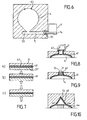
- figure 1 shows schematically a mixhead 1 of the L type comprising two opposed nozzles 11 for injecting two polymerizing reactants in a mixing chamber 12 to obtain a reacting mixture by jet-to-jet impingement of the reactant streams, said mixture being forced by a plunger in a second chamber 13 associated with a second plunger 14 which moves along the chamber 13 for pressing the mixture into a mold via an injection duct.
- the RIM Process may be advantageously used for rapidly molding of polyurethane products, the reactants being a polyisocyanate (NCO) compound and a polyhydroxyle OH compound.
- the reactants being a polyisocyanate (NCO) compound and a polyhydroxyle OH compound.
- the RIM Process will be used for molding an optical element such as a lens 2 having a substantially circular shape and a transversal thickness as shown on figures 2 and 3 .
- the molding device 3 comprises, as represented on figures 4 and 5 , two plates 31, 31' limiting a mold cavity 4 having a circular shape and a transversal thickness corresponding to those of the element 2 to be obtained.
- the mold 3 comprises an injection duct 5 having an inlet opening 51 and an outlet opening 52 connected by a spout 6 to a casting opening 42 provided on an entry side 43 of the mold cavity 4.
- the injection duct 5, the spout 6 and the mold cavity 4 are constituted by opposed recesses provided in the two plates 31, 31' of the mold 3 which are pressed together by screws 32.
- An elongated seal 41 is inserted between the two plates 31, 31' along the side of the mold cavity 4, said seal 41 resisting to the pressure inside the cavity 4 during filling and curing.
- the spout 6 provides a substantially flat space 60 having an axis x'x passing by the center of the circular mold cavity 4 and the center of the outlet opening 52 of the injection duct 5. Said spout 6 is limited by two flat faces 61, 61' and two diverging lateral sides 62, 62' which are symmetrically inclined on either side of the axis x'x and tangentially connect to the circular side 45 of the mold cavity 4.
- the spout has a narrow rectangular section progressively enlarging until the curvilinear casting opening 42 of the mold cavity 4 which widely opens along a sector A of the circular side 45, said sector being, for example of 90°.
- the flat faces 61, 61' of the spout 6 each have a substantially trapezoidal shape with a short base connecting to the outlet opening 52 of the injection duct 5 and a large curvilinear base extending along said sector A of the mold cavity.
- the outlet 15 of the pressing chamber 13 of the mixhead 1 is preferably directly connected to the inlet opening 51 of the injection duct 5, but this is not necessary.
- reaction mixture forced by the plunger 14 flows successively in the injection duct 5, the outlet opening 52 and the spout 6 for filling the mold cavity 4.
- the mixture obtained by jet-impingement of the reactants injected in the mixing chamber 12 contains a small quantity of air producing a bubbles nucleation as pressure drops suddenly in the turbulent flow. Due to the pressure in the pressing chamber 13 and the injection duct 5, such bubbles are dissolved in the mixture but, during curing in the mold cavity, the exothermic polymerizing reaction produces a growing of the bubbles. According to the invention, these bubbles are evacuated before solidification of the mixture, for avoiding entrapment of air bubbles in the lens.
- air evacuation means are provided on the side 44 of the cavity 4 opposed to the entry side 43.
- the mold cavity 4 extends along a median plane P which is preferably vertical or inclined by an angle different from zero, the evacuation side 44 being higher than the entry side 43.
- the flat space 60 of the spout 6 with a progressive enlarging transversal section produces a laminated flow of the mixture which emerges on the whole width of the cavity 4 and fills it without turbulence, thus avoiding air entrapment and permitting an immediate evacuation of the air bubbles which grow progressively in the liquid mixture.
- the air contained in the mixture remains dissolved by the pressure applied until the outlet 52 of the injection duct 5 and then, the progressive enlarging section of the spout 6 provides, between the flat faces 61, 61', a laminated flow with a progressively decreasing pressure.
- the bubbles appearing and growing progressively in this flow during filling the mold cavity 4 are regularly distributed in the mixture and may be immediately evacuated by the upper side 44 of the cavity 4 opposite to the spout 6.
- air evacuation means are provided on the upper side 44 of the cavity 4, for example two small vents 45 provided in the seal 41 surrounding the cavity 4 opening directly in the air or in a space 46 connected to vacuum means.
- FIG. 7 schematically represents the successive steps of the process.
- the mold clamping force is increased ( figure 7b ) and the seal 41 is compressed in order to close the vents 45.
- Flow of reactants by the vents is avoided and a post-injection pressure can be applied by the plunger 14 which, for example, may penetrate in the inlet opening 51 of the injection duct 5.
- the plunger 14 which, for example, may penetrate in the inlet opening 51 of the injection duct 5.
- the clamping force is one more time increased ( figure 7c ) in order to compensate for shrinkage at the surface of the lens 2.
- the molded piece may be withdrawn from the mold 3 and the part corresponding to the spout 6 may be broken, a rounded lens 2 without bubbles being obtained.
- the injection duct 5 is advantageous prolongated by a part 53 extending in the flow direction from the outlet opening 52 until a closed end 54, said part 53 forming a reserve for trapping the first part of the mixture flowing upwards in said injection duct 5 before entering in the enlarging spout 6.
- vent 45 may open in a second cavity 46 provided in the two plates 31, 31' and connected, for example, with vacuum means.
- each vent 45 is constituted by at least an aperture which is small enough to avoid the molded mixture to flow outside, said aperture being provided in the seal 41 and closed by compression of the seal as indicated on figure 7b .
- the mold may be provided with a larger aperture forming a unique vent which may be closed by a removable valve 7, said valve 7 being open during mold filling and being closed after air evacuation, for applying a post injection pressure in the mold cavity 4.
- the invention allows using of the R.I.M. process for obtaining optical lens from polymerized reactants with a high productivity. It should be noted that such a process allows a very broad choice of reactants.
- the aperture 47 may be closed by a plug 71 which is, at the ambient temperature, smaller than the aperture 47 for providing a slight play 72 allowing air evacuation during filling of the mold cavity by the injected mixture, said plug 71 expanding and closing said play 72 by increasing of its temperature when the mold cavity 4 is completely filled by the liquid mixture.
- the air evacuation means could be constituted by a space 73 largely opening on the evacuation side 44 of the mold cavity 4 for trapping air contained in the molded mixture, said mold cavity 4 and said space 73 being surrounded by a common continuous seal 41.
- a part of the mixture eventually penetrating in said space 73 could be eliminated after solidification and withdrawing the lens from the mold.
- the mold cavity 4 is advantageously vertical or inclined during filling and thus comprises the lowest part 43 constituting the entry side of the mixture and a highest part 44 constituting the air evacuation side.
- the mold cavity 4 is advantageously vertical or inclined during filling and thus comprises the lowest part 43 constituting the entry side of the mixture and a highest part 44 constituting the air evacuation side.
- the flat trapezoidal faces 61, 61' of the enlarging spout 6 may be symmetrically inclined by a slide angle on either side of the median plane P of the mold cavity 4, said faces 61, 61' slightly converging from the outlet opening 52 of the injection duct 55 to the inlet opening 42 of the mold cavity 4.
- the progressive decreasing of the pressure in the enlarging spout 6 may be controlled for having a better distribution of the mixture on the whole width of the mold cavity 4.
Landscapes
- Engineering & Computer Science (AREA)
- Mechanical Engineering (AREA)
- Manufacturing & Machinery (AREA)
- Health & Medical Sciences (AREA)
- Ophthalmology & Optometry (AREA)
- Injection Moulding Of Plastics Or The Like (AREA)
- Casting Or Compression Moulding Of Plastics Or The Like (AREA)
- Moulds For Moulding Plastics Or The Like (AREA)
- Eyeglasses (AREA)
Claims (21)
- Verfahren zur Herstellung einer optischen Linse mittels Gießen zweier polymerisierender Edukte, wobei die gegossene Linse erhalten wird mittels eines reaktiven Spritzgußverfahrens, umfassend die folgenden Schritte:Mischen von mindestens zwei polymerisierenden Edukten in einer Mischkammer (12), um eine reaktive Mischung zu erhalten,Erzwingen des Flusses der Mischung über einen Einspritzkanal (5) um unter Druck eine gedichtete Gussform (4) zu fiillen, die über eine Einlassseite (43), mit einer Abgussöffnung (42) und eine Auslass-Seite (44) gegenüber zu der Einlass-Seite (43) verfiigt, unddie Auslass-Seite (44) der Gussform (4) ist mit Mitteln (45) versehen ist, um während des Befüllens der Form, Luft, die eventuell in der Mischung enthalten ist, vor Verfestigung der Linse abzuziehen, dadurch gekennzeichnet, dasseine laminare Strömung der Mischung in einem Einfüllstutzen (6) bereitgestellt wird,wobei der Einfüllstutzen (6) einen sukzessiv anwachsenden transversalen Querschnitt aufweist zwischen einer Auslassöffnung (52) des Einspritzkanals (5) und der Abgussöffnung (42) der Gussform (4); um jeglichen Turbulenzenbereich innerhalb der laminaren Strömung zu vermeiden, wobei der Einspritzkanal (5) die Mischkammer (12) mit dem Einfüllstutzen (6) verbindet.
- Verfahren gemäß Anspruch 1 zur Herstellung einer optischen Linse, die im Wesentlichen von runder Form ist und im Wesentlichen eine gleichbleibende transversale Stärke hat, wobei die gedichtete Gussform (4) von im Wesentlichen runder Form ist und eine transversale Stärke entsprechend zu jener der Linse aufweist und wobei der Einfiillstutzen (6) einen im Wesentlichen flachen Raum (60) bereitstellt, welcher eine Achse (X'X) aufweist, die im Wesentlichen durch das Zentrum der Gussform (4) verläuft und durch zwei ebene Flächen (61, 61') begrenzt wird, und zwei auseinander laufende Seiten (62, 62') aufweist, die an jeder Seite der genannten Achse (X'X) geneigt ist und tangential verbunden mit der runden Form (45) der Gussform (4) ist.
- Verfahren gemäß Anspruch 2, wobei die Abgussöffnung (42) der Gussform (4) sich hauptsächlich entlang eines Sektors (A) der runden Form (45) der Gussform (4) öffnet, wobei die ebenen Flächen (61, 61') des Einfüllstutzens (6) jeweils von im Wesentlichen trapezförmiger Form sind mit einer großen krummlinigen Basis, die sich entlang des Sektors (A) der Gussform (4) erstreckt und eine kurze Basis, die verbunden ist mit der Auslassöffnung (52) des Einspritzkanals (5).
- Verfahren gemäß einem der Ansprüche 1 bis 3, wobei die Gussform (4) und der Einfüllstutzen (6) gegen die Horizontale geneigt sind, wobei die Gussform (4) eine tiefstliegende Einlass-Seite und eine am höchstliegende Auslass-Seite aufweist.
- Verfahren gemäß einem der vorhergegangenen Ansprüche, umfassend einen Schritt zur Kompression der gegossenen Mischung, nachdem die Gussform (4) vollständig gefüllt worden ist.
- Verfahren gemäß einem der vorangegangenen Ansprüche umfassend den Schritt des Einschließens eines ersten Teils der Mischung flussanwärts im Einspritzfluß in einen Endabschnitt (53) des Einspritzkanals, der zwischen der Auslassöffnung (52) und einem geschlossenen Ende (54) vorgesehen ist.
- Verfahren gemäß einem der vorangegangenen Ansprüche, wobei die Gussform von zwei Platten (31, 31') begrenzt wird, zwischen welchen eine runde Dichtung (41) eingesetzt wird, die zumindest eine Abzugsöffnung (45) zum Auslassen der Luft während des Befüllens der Form, wobei das Verfahren die Schritte umfasst der Ausübung einer erhöhten Klemmkraft zwischen den Platten (31, 31'), welche die Gussform (4) begrenzen, am Ende des Befüllens der Form, zum Komprimieren der runden Dichtung und Schließen der Abzugöffnung (45) und dann Anwenden eines Post-EinspritzDrucks in die gegossene Mischung.
- Verfahren gemäß Anspruch 7, wobei die Klemmkraft, welche die runde Dichtung (41) zusammenpresst, während dem Ausheilen der Edukte erhöht wird, um Schrumpf auszugleichen.
- Verfahren gemäß einem der vorangegangenen Ansprüche, umfassend den Schritt des Ansammelns der ausgelassenen Luft in einem Raum (73), der auf der Auslass-Seite (44) vorgesehen ist.
- Verfahren gemäß einem der Ansprüche 1 bis 8, umfassend die Schritte des Auslassens der Luft mittels einer Öffnung (47), die auf der Auslass-Seite (44) der Gussform (4) vorgesehen ist und Verschließen der Öffnung (47) wenn die Gussform (4) vollständig gefüllt ist mit der eingespritzten Mischung.
- Prozess gemäß einem der vorangegangenen Ansprüche, wobei ein Post-Einspritzdruck auf die Spritzform (4) ausgeübt wird, nach dem vollständigen Befüllen und Luft-Auslassen, wobei der Druck die Dichtung (41) komprimiert, und Schließen der Abzugsöffnung (45).
- Gußwerkzeug zur Herstellung einer optischen Linse (2), die im Wesentlichen von runder Form ist und im Wesentlichen eine regelmäßige transversale Stärke aufweist, wobei das Gußwerkzeug umfasst:- eine Mischkammer (12) zur Vorbereitung einer Mischung die gegossen werden soll,- eine gedichtete Gussform (4) mit einer im Wesentlichen runden Form, welche ein Zentrum und eine transversale Stärke aufweist, die jener der Linse, die erhalten werden soll, entspricht, wobei die Gussform (4) begrenzt wird durch zwei Platten (31,31') zwischen welchen eine längliche Dichtung (41) eingesetzt wird, welche die Gussform (4) umgibt und eine Einlass-Seite (43) aufweist, die mit einer Abgussöffnung (42) versehen ist, und eine Auslass-Seite (44), welche der Einlass-Seite (43) gegenüberliegt,- einen Einspritzkanal (5), der die Mischkammer (12) mit der Gussform (4) verbindet, wobei der Einspritzkanal eine Auslassöffnung (52) aufweist,- ein Einfüllstutzen (6), welcher die Auslassöffnung (52) des Einspritzkanals (5) mit der Abgussöffnung (41) der Gussform (4) verbindet,- Mittel zum Befüllen (14) zum Erzwingen des Flusses der Mischung von der Mischkammer (12) zu der Gussform (4) über den Einspritzkanal (5) den Einfüllstutzen (6) zum Befüllen der Gussform (4) unter Druck,- mindestens eine Abzugsöffnung (45), die an der Auslass-Seite (44) der Gussform (4) vorgesehen ist und verbunden ist mit Luftauslassmitteln (7), und dadurch gekennzeichnet, dass- der Einfüllstutzen (6) einen im Wesentlichen flachen Raum (60) bereitstellt, der eine Achse (X'X) aufweist, die im Wesentlichen durch das Zentrum der Gussform (4) reicht und begrenzt wird durch zwei ebene Flächen (61, 61') sowie zwei auseinander laufende Seiten (62, 62'), die an jeder Seite der Achse (X'X) geneigt sind und tangential verbunden sind mit der runden Form (45) der Gussform (4).
- Gußwerkzeug gemäß Anspruch 12, wobei der Einspritzkanal durch einen Abschnitt (53) verlängert wird, welcher sich in Flussrichtung von der Auslassöffnung (52) bis zu einem geschlossenen Ende (54) erstreckt, wobei der Abschnitt (53) einen Rückhalt zum Einschließen eines ersten Abschnitts der Mischung, die flussanwärts in den Einspritzkanal (5) fließt.
- Gußwerkzeug gemäß einem der Ansprüche 12 und 13, wobei jede Abzugsöffnung (45), die auf der Auslass-Seite (44) der Gussform (4) vorgesehen ist, zumindest aus einer Öffnung besteht, die klein genug ist um zu verhindern, dass Edukte, die in der Mischung enthalten sind, nach außen fließen.
- Gußwerkzeug gemäß einem der Ansprüche 12 und 13, wobei jede Abzugsöffnung (45), die an der Auslass-Seite der Gussform (4) vorgesehen ist, geschlossen wird durch ein entfernbares Ventil (7), wobei das Ventil während des Befüllens der Form geöffnet ist und geschlossen wird nach Luftauslass, um einen Post-Einspritzdruck in der Gussform (4) auszuüben.
- Gußwerkzeug gemäß einem der Ansprüche 12 bis 15, umfassend einen Raum (73), der sich auf der Auslass-Seite (44) der Gussform (4) öffnet, zum Einschließen von Luft, die in der zu gießenden Mischung enthalten ist, wobei die Gussform (4) und der Raum (73) umgeben sind von einer gemeinsamen durchgehenden Dichtung.
- Gußwerkzeug gemäß einem der Ansprüche 12 bis 16, wobei jede der Abzugsöffnungen eine Öffnung (45) aufweist, die in der Dichtung (41) auf der Auslass-Seite (44) der Gussform (4) vorgesehen ist und verbunden mit den Luftauslassmitteln ist.
- Gußwerkzeug gemäß Anspruch 17, wobei die Öffnung mittels eines Stöpsels (71) verschlossen wird, der ein geringfügiges Spiel (72) hat, um Luftauslass während dem Befüllen der Gussform (4) mit der eingespritzten Mischung zu erlauben, wobei der Stöpsel (71) sich ausdehnt und das Spiel (72) mit zunehmen seiner Temperatur schließt, wenn die Gussform (4) vollständig gefüllt ist.
- Gußwerkzeug gemäß einem der Ansprüche 12 bis 18, wobei die Gussform (4) sich entlang einer geneigten Mittenebene erstreckt, die einen von Null verschiedenen Winkel mit der Horizontalen einschließt und einen tiefsten Abschnitt und einen höchsten Abschnitt umfasst, welche jeweils die Einlass-Seite (43) und die Auslass-Seite (44) der Gussform (4) darstellen.
- Gußwerkzeug gemäß Anspruch 19, wobei die ebenen trapezförmigen Flächen (61, 61') des anwachsenden Einfüllstutzens (6) im Wesentlichen parallel zu der dritten Mittenebene (P) der Gussform (4) sind.
- Gußwerkzeug gemäß Anspruch 19, wobei die ebenen trapezförmigen Flächen (61, 61') des anwachsenden Einfüllstutzens (6) symmetrisch geneigt sind um einen kleinen Winkel auf jeder Seite der Mittenebene (P) der Gussform (4), wobei die ebenen Flächen leicht auseinander laufen von der Auslassöffnung (52) des Einspritzkanals (5) zu der Einlassöffnung (42) der Gussform (4).
Priority Applications (6)
| Application Number | Priority Date | Filing Date | Title |
|---|---|---|---|
| EP04300102A EP1568474B1 (de) | 2004-02-27 | 2004-02-27 | Verfahren und Vorrichtung zur Herstellung von einer optischen Linse |
| DE602004015240T DE602004015240D1 (de) | 2004-02-27 | 2004-02-27 | Verfahren und Vorrichtung zur Herstellung von einer optischen Linse |
| AT04300102T ATE402006T1 (de) | 2004-02-27 | 2004-02-27 | Verfahren und vorrichtung zur herstellung von einer optischen linse |
| US10/598,357 US7950917B2 (en) | 2004-02-27 | 2005-02-25 | Process and installation for molding an optical lens |
| PCT/EP2005/002104 WO2005084927A1 (en) | 2004-02-27 | 2005-02-25 | Process and installation for molding an optical lens |
| EP05715608A EP1720695A1 (de) | 2004-02-27 | 2005-02-25 | Verfahren und anlage zum formen einer optischen linse |
Applications Claiming Priority (1)
| Application Number | Priority Date | Filing Date | Title |
|---|---|---|---|
| EP04300102A EP1568474B1 (de) | 2004-02-27 | 2004-02-27 | Verfahren und Vorrichtung zur Herstellung von einer optischen Linse |
Publications (2)
| Publication Number | Publication Date |
|---|---|
| EP1568474A1 EP1568474A1 (de) | 2005-08-31 |
| EP1568474B1 true EP1568474B1 (de) | 2008-07-23 |
Family
ID=34746170
Family Applications (2)
| Application Number | Title | Priority Date | Filing Date |
|---|---|---|---|
| EP04300102A Expired - Lifetime EP1568474B1 (de) | 2004-02-27 | 2004-02-27 | Verfahren und Vorrichtung zur Herstellung von einer optischen Linse |
| EP05715608A Withdrawn EP1720695A1 (de) | 2004-02-27 | 2005-02-25 | Verfahren und anlage zum formen einer optischen linse |
Family Applications After (1)
| Application Number | Title | Priority Date | Filing Date |
|---|---|---|---|
| EP05715608A Withdrawn EP1720695A1 (de) | 2004-02-27 | 2005-02-25 | Verfahren und anlage zum formen einer optischen linse |
Country Status (5)
| Country | Link |
|---|---|
| US (1) | US7950917B2 (de) |
| EP (2) | EP1568474B1 (de) |
| AT (1) | ATE402006T1 (de) |
| DE (1) | DE602004015240D1 (de) |
| WO (1) | WO2005084927A1 (de) |
Families Citing this family (9)
| Publication number | Priority date | Publication date | Assignee | Title |
|---|---|---|---|---|
| US7731872B2 (en) | 2006-05-31 | 2010-06-08 | Coopervision International Holding Company, Lp | Methods and systems for forming ophthalmic lens mold assemblies |
| EP1967258A1 (de) * | 2007-03-06 | 2008-09-10 | Interglass Technology AG | Verfahren zum Mischen einer Flüssigkeit mit mindestens einer weiteren Substanz und Entgasen des Gemisches und für die Abgabe des Gemisches |
| FR2920109A1 (fr) * | 2007-08-22 | 2009-02-27 | Automatic System Sarl | Installation pour l'elaboration de pieces a base d'une matiere moulable a au moins deux composants |
| EP2237945B1 (de) * | 2008-01-08 | 2020-04-01 | LG Innotek Co., Ltd. | Kameramodul und verfahren zur herstellung eines kameramoduls |
| EP2345625A1 (de) * | 2008-11-13 | 2011-07-20 | Sumitomo Electric Industries, Ltd. | Bauteil für ein formelement, verfahren zur herstellung des elements und element |
| JP2010264652A (ja) * | 2009-05-14 | 2010-11-25 | Fujifilm Corp | 造形物の製造方法及び製造装置 |
| US20120286435A1 (en) * | 2011-03-04 | 2012-11-15 | Ppg Industries Ohio, Inc. | Process for preparing molded optical articles |
| WO2017023351A1 (en) * | 2015-07-31 | 2017-02-09 | Gentex Optics, Inc. | System, mold and method for forming an ophthalmic lens |
| CN116001209A (zh) * | 2022-12-29 | 2023-04-25 | 歌尔光学科技有限公司 | 一种注胶模具及注胶系统 |
Family Cites Families (17)
| Publication number | Priority date | Publication date | Assignee | Title |
|---|---|---|---|---|
| US3368245A (en) * | 1965-04-05 | 1968-02-13 | Henry J. Witkowski | Plastic mold |
| US3894710A (en) * | 1973-08-29 | 1975-07-15 | George M J Sarofeen | Mold forms coating synthetic resin lenses |
| JPS5849170B2 (ja) * | 1977-10-25 | 1983-11-02 | 旭化成株式会社 | コ−トハンガ−型ゲ−トを有する射出成形用金型 |
| US5523045A (en) * | 1983-04-13 | 1996-06-04 | American National Can Company | Methods for injection molding and blow-molding multi-layer plastic articles |
| US4693446A (en) * | 1985-09-20 | 1987-09-15 | Techna Vision, Inc. | Gasket for molding plastic lenses |
| JP2872247B2 (ja) * | 1988-06-21 | 1999-03-17 | 久司 小嶋 | パルス射出圧縮成形法 |
| DE3833868A1 (de) * | 1988-10-05 | 1990-04-12 | Hofstetter Ag Otto | Verfahren zum spritzgiessen von pet-formlingen und anguss-system |
| US5656210A (en) * | 1995-03-31 | 1997-08-12 | Johnson & Johnson Vision Products, Inc. | Reaction injection molding as a process to prepare contact lenses |
| US6214261B1 (en) * | 1998-03-23 | 2001-04-10 | Ppg Industries Ohio, Inc. | Method for forming a molded edge seal |
| US7002744B2 (en) * | 1999-11-22 | 2006-02-21 | Younger Mfg. Co. Dba Younger Optics | Polarized optical part using high impact polyurethane-based material |
| ATE317758T1 (de) * | 2001-01-24 | 2006-03-15 | Novartis Pharma Gmbh | Verfahren zur herstellung von linsen |
| EP1372524B1 (de) * | 2001-03-16 | 2006-09-20 | Novartis AG | Verfahren zum giessformen von opthalmischen linsen |
| US6416689B1 (en) * | 2001-03-21 | 2002-07-09 | Essilor International Compagnie General D'optique | Method for molding plastic lenses |
| JP3981808B2 (ja) * | 2001-11-19 | 2007-09-26 | 信越化学工業株式会社 | 射出成形金型及びそれを用いた射出成形品の製造方法 |
| US6872335B2 (en) * | 2002-03-12 | 2005-03-29 | Technology Resource International Corporation | Method and apparatus for holding a mold assembly and molding an optical lens using the same |
| US7682531B2 (en) * | 2002-04-08 | 2010-03-23 | Hoya Corporation | Process for producing optical member |
| US6843940B2 (en) * | 2002-08-05 | 2005-01-18 | Essilor International Compagnie Generale D'optique | Method and mold for molding plastic lenses |
-
2004
- 2004-02-27 EP EP04300102A patent/EP1568474B1/de not_active Expired - Lifetime
- 2004-02-27 AT AT04300102T patent/ATE402006T1/de not_active IP Right Cessation
- 2004-02-27 DE DE602004015240T patent/DE602004015240D1/de not_active Expired - Lifetime
-
2005
- 2005-02-25 EP EP05715608A patent/EP1720695A1/de not_active Withdrawn
- 2005-02-25 US US10/598,357 patent/US7950917B2/en not_active Expired - Fee Related
- 2005-02-25 WO PCT/EP2005/002104 patent/WO2005084927A1/en not_active Ceased
Also Published As
| Publication number | Publication date |
|---|---|
| WO2005084927A1 (en) | 2005-09-15 |
| EP1568474A1 (de) | 2005-08-31 |
| EP1720695A1 (de) | 2006-11-15 |
| US7950917B2 (en) | 2011-05-31 |
| DE602004015240D1 (de) | 2008-09-04 |
| US20080230931A1 (en) | 2008-09-25 |
| ATE402006T1 (de) | 2008-08-15 |
Similar Documents
| Publication | Publication Date | Title |
|---|---|---|
| EP1568474B1 (de) | Verfahren und Vorrichtung zur Herstellung von einer optischen Linse | |
| KR101555376B1 (ko) | 주조 장치 | |
| US6365083B1 (en) | Method of forming molded product from three or more semi-molded products and mold assembly therefor | |
| CN118510643A (zh) | 用于生产多单元部件的方法 | |
| US4377197A (en) | Apparatus and method for casting lead into plastic for side terminal batteries | |
| US6666999B1 (en) | Gas assisted moulding | |
| WO2007029101A3 (en) | Vessel and method of manufacture thereof | |
| US7108823B2 (en) | Staged compression molding process | |
| US20160067892A1 (en) | Method and device for producing a drainage element and drainage element produced thereby | |
| CN118238357B (zh) | 一种多细长部位塑料件的注塑模具及注塑方法 | |
| CN219254061U (zh) | 一种铝控制臂铸件砂芯的制作模具 | |
| US4158382A (en) | Apparatus for casting lead into plastic for side terminal batteries | |
| CN216912042U (zh) | 一种方便脱模的高密封性压铸模具 | |
| CN210702392U (zh) | 一种汽车飞轮罩用铸造模具 | |
| CN115150538A (zh) | 车载摄像装置、外壳压铸模具以及整形模具 | |
| CN209649403U (zh) | 一种注塑模具的抽芯机构 | |
| CN223720076U (zh) | 一种具有顶出排料功能的模具 | |
| CN221968844U (zh) | 一种柜体盖板成型模具 | |
| EP3609671B1 (de) | Formverfahren und vorrichtung | |
| CN119502244B (zh) | 一种扬声器支架生产用注塑成型设备及其使用方法 | |
| CN222178523U (zh) | 一种用于母座连接器的注塑模具 | |
| US5670233A (en) | Acoustic window and method for making the same | |
| WO2007078356A2 (en) | Staged compression molding process | |
| CN218429717U (zh) | 一种转换方向的滑块抽芯结构 | |
| CN213919374U (zh) | 一种应用于高抗冲高耐光氧老化户外桌的注塑模具 |
Legal Events
| Date | Code | Title | Description |
|---|---|---|---|
| PUAI | Public reference made under article 153(3) epc to a published international application that has entered the european phase |
Free format text: ORIGINAL CODE: 0009012 |
|
| AK | Designated contracting states |
Kind code of ref document: A1 Designated state(s): AT BE BG CH CY CZ DE DK EE ES FI FR GB GR HU IE IT LI LU MC NL PT RO SE SI SK TR |
|
| AX | Request for extension of the european patent |
Extension state: AL LT LV MK |
|
| 17P | Request for examination filed |
Effective date: 20060228 |
|
| AKX | Designation fees paid |
Designated state(s): AT BE BG CH CY CZ DE DK EE ES FI FR GB GR HU IE IT LI LU MC NL PT RO SE SI SK TR |
|
| 17Q | First examination report despatched |
Effective date: 20070726 |
|
| GRAP | Despatch of communication of intention to grant a patent |
Free format text: ORIGINAL CODE: EPIDOSNIGR1 |
|
| GRAS | Grant fee paid |
Free format text: ORIGINAL CODE: EPIDOSNIGR3 |
|
| GRAA | (expected) grant |
Free format text: ORIGINAL CODE: 0009210 |
|
| AK | Designated contracting states |
Kind code of ref document: B1 Designated state(s): AT BE BG CH CY CZ DE DK EE ES FI FR GB GR HU IE IT LI LU MC NL PT RO SE SI SK TR |
|
| REG | Reference to a national code |
Ref country code: GB Ref legal event code: FG4D |
|
| REG | Reference to a national code |
Ref country code: CH Ref legal event code: EP |
|
| REG | Reference to a national code |
Ref country code: IE Ref legal event code: FG4D |
|
| REF | Corresponds to: |
Ref document number: 602004015240 Country of ref document: DE Date of ref document: 20080904 Kind code of ref document: P |
|
| NLV1 | Nl: lapsed or annulled due to failure to fulfill the requirements of art. 29p and 29m of the patents act | ||
| PG25 | Lapsed in a contracting state [announced via postgrant information from national office to epo] |
Ref country code: ES Free format text: LAPSE BECAUSE OF FAILURE TO SUBMIT A TRANSLATION OF THE DESCRIPTION OR TO PAY THE FEE WITHIN THE PRESCRIBED TIME-LIMIT Effective date: 20081103 Ref country code: NL Free format text: LAPSE BECAUSE OF FAILURE TO SUBMIT A TRANSLATION OF THE DESCRIPTION OR TO PAY THE FEE WITHIN THE PRESCRIBED TIME-LIMIT Effective date: 20080723 Ref country code: PT Free format text: LAPSE BECAUSE OF FAILURE TO SUBMIT A TRANSLATION OF THE DESCRIPTION OR TO PAY THE FEE WITHIN THE PRESCRIBED TIME-LIMIT Effective date: 20081223 |
|
| PG25 | Lapsed in a contracting state [announced via postgrant information from national office to epo] |
Ref country code: BG Free format text: LAPSE BECAUSE OF FAILURE TO SUBMIT A TRANSLATION OF THE DESCRIPTION OR TO PAY THE FEE WITHIN THE PRESCRIBED TIME-LIMIT Effective date: 20081023 Ref country code: AT Free format text: LAPSE BECAUSE OF FAILURE TO SUBMIT A TRANSLATION OF THE DESCRIPTION OR TO PAY THE FEE WITHIN THE PRESCRIBED TIME-LIMIT Effective date: 20080723 Ref country code: FI Free format text: LAPSE BECAUSE OF FAILURE TO SUBMIT A TRANSLATION OF THE DESCRIPTION OR TO PAY THE FEE WITHIN THE PRESCRIBED TIME-LIMIT Effective date: 20080723 Ref country code: SI Free format text: LAPSE BECAUSE OF FAILURE TO SUBMIT A TRANSLATION OF THE DESCRIPTION OR TO PAY THE FEE WITHIN THE PRESCRIBED TIME-LIMIT Effective date: 20080723 |
|
| PG25 | Lapsed in a contracting state [announced via postgrant information from national office to epo] |
Ref country code: BE Free format text: LAPSE BECAUSE OF FAILURE TO SUBMIT A TRANSLATION OF THE DESCRIPTION OR TO PAY THE FEE WITHIN THE PRESCRIBED TIME-LIMIT Effective date: 20080723 |
|
| PG25 | Lapsed in a contracting state [announced via postgrant information from national office to epo] |
Ref country code: DK Free format text: LAPSE BECAUSE OF FAILURE TO SUBMIT A TRANSLATION OF THE DESCRIPTION OR TO PAY THE FEE WITHIN THE PRESCRIBED TIME-LIMIT Effective date: 20080723 Ref country code: EE Free format text: LAPSE BECAUSE OF FAILURE TO SUBMIT A TRANSLATION OF THE DESCRIPTION OR TO PAY THE FEE WITHIN THE PRESCRIBED TIME-LIMIT Effective date: 20080723 |
|
| PG25 | Lapsed in a contracting state [announced via postgrant information from national office to epo] |
Ref country code: RO Free format text: LAPSE BECAUSE OF FAILURE TO SUBMIT A TRANSLATION OF THE DESCRIPTION OR TO PAY THE FEE WITHIN THE PRESCRIBED TIME-LIMIT Effective date: 20080723 Ref country code: SK Free format text: LAPSE BECAUSE OF FAILURE TO SUBMIT A TRANSLATION OF THE DESCRIPTION OR TO PAY THE FEE WITHIN THE PRESCRIBED TIME-LIMIT Effective date: 20080723 Ref country code: CZ Free format text: LAPSE BECAUSE OF FAILURE TO SUBMIT A TRANSLATION OF THE DESCRIPTION OR TO PAY THE FEE WITHIN THE PRESCRIBED TIME-LIMIT Effective date: 20080723 |
|
| PLBE | No opposition filed within time limit |
Free format text: ORIGINAL CODE: 0009261 |
|
| STAA | Information on the status of an ep patent application or granted ep patent |
Free format text: STATUS: NO OPPOSITION FILED WITHIN TIME LIMIT |
|
| 26N | No opposition filed |
Effective date: 20090424 |
|
| PG25 | Lapsed in a contracting state [announced via postgrant information from national office to epo] |
Ref country code: IT Free format text: LAPSE BECAUSE OF FAILURE TO SUBMIT A TRANSLATION OF THE DESCRIPTION OR TO PAY THE FEE WITHIN THE PRESCRIBED TIME-LIMIT Effective date: 20080723 |
|
| PG25 | Lapsed in a contracting state [announced via postgrant information from national office to epo] |
Ref country code: MC Free format text: LAPSE BECAUSE OF NON-PAYMENT OF DUE FEES Effective date: 20090228 |
|
| REG | Reference to a national code |
Ref country code: CH Ref legal event code: PL |
|
| PG25 | Lapsed in a contracting state [announced via postgrant information from national office to epo] |
Ref country code: CH Free format text: LAPSE BECAUSE OF NON-PAYMENT OF DUE FEES Effective date: 20090228 Ref country code: LI Free format text: LAPSE BECAUSE OF NON-PAYMENT OF DUE FEES Effective date: 20090228 |
|
| PG25 | Lapsed in a contracting state [announced via postgrant information from national office to epo] |
Ref country code: IE Free format text: LAPSE BECAUSE OF NON-PAYMENT OF DUE FEES Effective date: 20090227 Ref country code: SE Free format text: LAPSE BECAUSE OF FAILURE TO SUBMIT A TRANSLATION OF THE DESCRIPTION OR TO PAY THE FEE WITHIN THE PRESCRIBED TIME-LIMIT Effective date: 20081023 |
|
| PG25 | Lapsed in a contracting state [announced via postgrant information from national office to epo] |
Ref country code: GR Free format text: LAPSE BECAUSE OF FAILURE TO SUBMIT A TRANSLATION OF THE DESCRIPTION OR TO PAY THE FEE WITHIN THE PRESCRIBED TIME-LIMIT Effective date: 20081024 |
|
| PG25 | Lapsed in a contracting state [announced via postgrant information from national office to epo] |
Ref country code: LU Free format text: LAPSE BECAUSE OF NON-PAYMENT OF DUE FEES Effective date: 20090227 |
|
| PGFP | Annual fee paid to national office [announced via postgrant information from national office to epo] |
Ref country code: FR Payment date: 20110311 Year of fee payment: 8 |
|
| PG25 | Lapsed in a contracting state [announced via postgrant information from national office to epo] |
Ref country code: HU Free format text: LAPSE BECAUSE OF FAILURE TO SUBMIT A TRANSLATION OF THE DESCRIPTION OR TO PAY THE FEE WITHIN THE PRESCRIBED TIME-LIMIT Effective date: 20090124 |
|
| PGFP | Annual fee paid to national office [announced via postgrant information from national office to epo] |
Ref country code: GB Payment date: 20110201 Year of fee payment: 8 |
|
| PG25 | Lapsed in a contracting state [announced via postgrant information from national office to epo] |
Ref country code: TR Free format text: LAPSE BECAUSE OF FAILURE TO SUBMIT A TRANSLATION OF THE DESCRIPTION OR TO PAY THE FEE WITHIN THE PRESCRIBED TIME-LIMIT Effective date: 20080723 |
|
| PG25 | Lapsed in a contracting state [announced via postgrant information from national office to epo] |
Ref country code: CY Free format text: LAPSE BECAUSE OF FAILURE TO SUBMIT A TRANSLATION OF THE DESCRIPTION OR TO PAY THE FEE WITHIN THE PRESCRIBED TIME-LIMIT Effective date: 20080723 |
|
| PGFP | Annual fee paid to national office [announced via postgrant information from national office to epo] |
Ref country code: DE Payment date: 20120424 Year of fee payment: 9 |
|
| GBPC | Gb: european patent ceased through non-payment of renewal fee |
Effective date: 20120227 |
|
| REG | Reference to a national code |
Ref country code: FR Ref legal event code: ST Effective date: 20121031 |
|
| PG25 | Lapsed in a contracting state [announced via postgrant information from national office to epo] |
Ref country code: GB Free format text: LAPSE BECAUSE OF NON-PAYMENT OF DUE FEES Effective date: 20120227 Ref country code: FR Free format text: LAPSE BECAUSE OF NON-PAYMENT OF DUE FEES Effective date: 20120229 |
|
| REG | Reference to a national code |
Ref country code: DE Ref legal event code: R119 Ref document number: 602004015240 Country of ref document: DE Effective date: 20130903 |
|
| PG25 | Lapsed in a contracting state [announced via postgrant information from national office to epo] |
Ref country code: DE Free format text: LAPSE BECAUSE OF NON-PAYMENT OF DUE FEES Effective date: 20130903 |