EP1568441B1 - Vorrichtung zur Herstellung von Zahnriemenformen - Google Patents
Vorrichtung zur Herstellung von Zahnriemenformen Download PDFInfo
- Publication number
- EP1568441B1 EP1568441B1 EP05007364A EP05007364A EP1568441B1 EP 1568441 B1 EP1568441 B1 EP 1568441B1 EP 05007364 A EP05007364 A EP 05007364A EP 05007364 A EP05007364 A EP 05007364A EP 1568441 B1 EP1568441 B1 EP 1568441B1
- Authority
- EP
- European Patent Office
- Prior art keywords
- profile
- trimming
- workpiece
- grinding wheel
- grinding
- Prior art date
- Legal status (The legal status is an assumption and is not a legal conclusion. Google has not performed a legal analysis and makes no representation as to the accuracy of the status listed.)
- Expired - Lifetime
Links
- 238000004519 manufacturing process Methods 0.000 title description 5
- 238000000227 grinding Methods 0.000 claims abstract description 86
- 238000000034 method Methods 0.000 claims abstract description 16
- 239000010432 diamond Substances 0.000 claims description 16
- 229910003460 diamond Inorganic materials 0.000 claims description 16
- 230000002093 peripheral effect Effects 0.000 claims description 5
- 238000009966 trimming Methods 0.000 claims 13
- 238000000465 moulding Methods 0.000 abstract 1
- 238000005520 cutting process Methods 0.000 description 3
- 238000003801 milling Methods 0.000 description 3
- 239000007921 spray Substances 0.000 description 3
- 239000000463 material Substances 0.000 description 2
- 229920013648 Perbunan Polymers 0.000 description 1
- 229910000831 Steel Inorganic materials 0.000 description 1
- 230000006978 adaptation Effects 0.000 description 1
- 238000010276 construction Methods 0.000 description 1
- 238000001816 cooling Methods 0.000 description 1
- 238000003754 machining Methods 0.000 description 1
- 239000011159 matrix material Substances 0.000 description 1
- 239000007787 solid Substances 0.000 description 1
- 239000010959 steel Substances 0.000 description 1
Images

Classifications
-
- B—PERFORMING OPERATIONS; TRANSPORTING
- B24—GRINDING; POLISHING
- B24B—MACHINES, DEVICES, OR PROCESSES FOR GRINDING OR POLISHING; DRESSING OR CONDITIONING OF ABRADING SURFACES; FEEDING OF GRINDING, POLISHING, OR LAPPING AGENTS
- B24B5/00—Machines or devices designed for grinding surfaces of revolution on work, including those which also grind adjacent plane surfaces; Accessories therefor
- B24B5/02—Machines or devices designed for grinding surfaces of revolution on work, including those which also grind adjacent plane surfaces; Accessories therefor involving centres or chucks for holding work
- B24B5/04—Machines or devices designed for grinding surfaces of revolution on work, including those which also grind adjacent plane surfaces; Accessories therefor involving centres or chucks for holding work for grinding cylindrical surfaces externally
-
- B—PERFORMING OPERATIONS; TRANSPORTING
- B24—GRINDING; POLISHING
- B24B—MACHINES, DEVICES, OR PROCESSES FOR GRINDING OR POLISHING; DRESSING OR CONDITIONING OF ABRADING SURFACES; FEEDING OF GRINDING, POLISHING, OR LAPPING AGENTS
- B24B19/00—Single-purpose machines or devices for particular grinding operations not covered by any other main group
- B24B19/02—Single-purpose machines or devices for particular grinding operations not covered by any other main group for grinding grooves, e.g. on shafts, in casings, in tubes, homokinetic joint elements
-
- B—PERFORMING OPERATIONS; TRANSPORTING
- B24—GRINDING; POLISHING
- B24B—MACHINES, DEVICES, OR PROCESSES FOR GRINDING OR POLISHING; DRESSING OR CONDITIONING OF ABRADING SURFACES; FEEDING OF GRINDING, POLISHING, OR LAPPING AGENTS
- B24B5/00—Machines or devices designed for grinding surfaces of revolution on work, including those which also grind adjacent plane surfaces; Accessories therefor
- B24B5/02—Machines or devices designed for grinding surfaces of revolution on work, including those which also grind adjacent plane surfaces; Accessories therefor involving centres or chucks for holding work
- B24B5/04—Machines or devices designed for grinding surfaces of revolution on work, including those which also grind adjacent plane surfaces; Accessories therefor involving centres or chucks for holding work for grinding cylindrical surfaces externally
- B24B5/045—Machines or devices designed for grinding surfaces of revolution on work, including those which also grind adjacent plane surfaces; Accessories therefor involving centres or chucks for holding work for grinding cylindrical surfaces externally with the grinding wheel axis perpendicular to the workpiece axis
-
- B—PERFORMING OPERATIONS; TRANSPORTING
- B24—GRINDING; POLISHING
- B24B—MACHINES, DEVICES, OR PROCESSES FOR GRINDING OR POLISHING; DRESSING OR CONDITIONING OF ABRADING SURFACES; FEEDING OF GRINDING, POLISHING, OR LAPPING AGENTS
- B24B53/00—Devices or means for dressing or conditioning abrasive surfaces
- B24B53/04—Devices or means for dressing or conditioning abrasive surfaces of cylindrical or conical surfaces on abrasive tools or wheels
- B24B53/047—Devices or means for dressing or conditioning abrasive surfaces of cylindrical or conical surfaces on abrasive tools or wheels equipped with one or more diamonds
-
- B—PERFORMING OPERATIONS; TRANSPORTING
- B24—GRINDING; POLISHING
- B24B—MACHINES, DEVICES, OR PROCESSES FOR GRINDING OR POLISHING; DRESSING OR CONDITIONING OF ABRADING SURFACES; FEEDING OF GRINDING, POLISHING, OR LAPPING AGENTS
- B24B53/00—Devices or means for dressing or conditioning abrasive surfaces
- B24B53/06—Devices or means for dressing or conditioning abrasive surfaces of profiled abrasive wheels
- B24B53/07—Devices or means for dressing or conditioning abrasive surfaces of profiled abrasive wheels by means of forming tools having a shape complementary to that to be produced, e.g. blocks, profile rolls
-
- B—PERFORMING OPERATIONS; TRANSPORTING
- B24—GRINDING; POLISHING
- B24B—MACHINES, DEVICES, OR PROCESSES FOR GRINDING OR POLISHING; DRESSING OR CONDITIONING OF ABRADING SURFACES; FEEDING OF GRINDING, POLISHING, OR LAPPING AGENTS
- B24B53/00—Devices or means for dressing or conditioning abrasive surfaces
- B24B53/06—Devices or means for dressing or conditioning abrasive surfaces of profiled abrasive wheels
- B24B53/08—Devices or means for dressing or conditioning abrasive surfaces of profiled abrasive wheels controlled by information means, e.g. patterns, templets, punched tapes or the like
- B24B53/085—Devices or means for dressing or conditioning abrasive surfaces of profiled abrasive wheels controlled by information means, e.g. patterns, templets, punched tapes or the like for workpieces having a grooved profile, e.g. gears, splined shafts, threads, worms
Definitions
- a device with the features a) - e) is, for example, from the GB-A-1 253 685 known.
- Timing belt forms are usually steel tube rolls which are straight-toothed on their shell circumference and used as an inner core in the manufacture of toothed belts, e.g. from Perbunan gum or plastic, needed.
- the heated toothed belt material is pressed into the toothing of the toothed belt shape.
- the toothing of the toothed belt forms thus forms the die of the toothed belt toothing.
- timing belt shapes It is known to produce timing belt shapes by milling from cylindrical blanks.
- the requirements for the accuracy of the tooth geometries of timing belts has increased enormously.
- the tooth surface should be as smooth as possible, i. if possible, have no illustrations of existing in the timing belt shapes Fräsriefen.
- the device according to the invention allows a method for the production of toothed belt forms in which by means of at least one rotating grinding wheel with a profiled circumference in the pre-machining substantially cylindrical circumference of a workpiece, a die of the desired toothed belt toothing is incorporated, wherein the circumferential profile of the profile of a complete tooth groove of desired timing belt shape corresponds.
- the die for the timing belt is not milled but by grinding with specially profiled grinding wheels with a grinding motion parallel to Longitudinal axis of the workpiece generated.
- Tooth groove is understood to mean the full area from the head of a tooth to the head of the adjacent tooth. The grinding of two adjacent tooth grooves thus leads to a complete tooth of the toothed belt shape being produced, ie also the outer diameter of the toothed belt shape is ground.
- the shrinkage of the toothed belt material during cooling in the manufacturing process must be considered.
- profiled grinding wheels also allows to easily create the finest substructures in the tooth profile, z. B. a wavy sub-profile in the tooth flanks. For this purpose, for. B. running parallel to the toothed belt axis forming channels in the profile. Timing belts with such sub-profiles are in the DE 199 08 672 C1 disclosed.
- the dressing is required due to the gradual wear of the grinding wheel.
- the use of a profile dressing with profiled dressing area has the advantage that a complex CNC control for the movement of other dressing means, such as a dressing pin, is not required because the profiled dressing area predetermines a solid profile.
- a profile dressing element is therefore particularly useful if variations of the profile shape are not needed and high quantities are to be produced with identical gearing geometries.
- the device according to the invention can also be designed such that the at least one profile dressing element is positioned and adjustable relative to the workpiece holder such that viewed in the direction of the longitudinal center axis of the at least one clamped workpiece, the projection of the profile of the dressing area on a workpiece face the profile of the cross section of corresponds to a grinding process aspired cut.
- the profile of the profile of the dressing area of the dressing element specifies the cutting path exactly for each grinding operation, i.
- the dressing area must be exactly in alignment with the desired cutting process. Thus, it is completely irrelevant how much was removed during the dressing process from the diameter of the grinding wheel.
- the workpiece is rotated about an angle corresponding to the pitch circle pitch of the toothing geometry.
- the grinding wheel is fed to the workpiece for re-dressing over the dressing area of the dressing element and in continuation of a straight-line translational movement for the next grinding operation. Assuming that the dressing area has not been significantly worn, the dressing wheel is always at the correct relative height after dressing, relative to the workpiece. Any signs of wear on the dressing area can be compensated by a manual or automated adjustment.
- the relative movement between the grinding wheel and the workpiece can be achieved by a movement of the grinding wheel with respect to a machine frame or a movement of a tool holder.
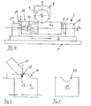
- Fig. 1 shows a grinding device with a machine frame 1, on which a horizontally movable grinding table 2 is mounted.
- the grinding table 2 carries a workpiece holder 3, in which the roller-shaped blank 4 is clamped for a toothed belt shape between a dividing head 16 and an abutment 17.
- the blank 4 can be controlled by a turntable 6 about a horizontal axis of rotation 7 is rotated.
- the axis of rotation 7 simultaneously forms the longitudinal center axis of the blank 4 in the blank 4.
- the workpiece holder 3 comprises a high-precision direct measuring system, not separately shown here, which permits an exact rotational angle adjustment.
- Above the workpiece holder 3, a grinding wheel 9 is rotatably fixed to a grinding wheel holder 8.
- the grinding wheel holder 8 is highly precisely controlled in the vertical direction movable.
- the counter profile of the toothed belt toothing must be incorporated in the circumference of the blank 4, the toothing being rectilinear and constant in the direction of the longitudinal central axis of the blank 4.
- the circumference now forms, seen in cross-section, the die for the toothed belt toothing.
- the grinding wheel 9 has on its circumference a profile 10, which is visible in an enlarged view in Fig. 2.
- the circumferential profile 10 of the grinding wheel 9 corresponds the desired profile of a Zahnnut the timing belt shape.
- the circumferential profile 10 of the grinding wheel 9 can be re-dressed with a dressing pin 11 before each grinding operation. This is done with the help of a CNC-controlled process.
- the Abrichtit 11 is axially movable relative to the axis of rotation of the grinding wheel as well as in the radial direction.
- the dressing pin 11 also has a dressing pivot axis 12, which extends substantially perpendicular to the axial and radial directions and through the center of a round diamond 13 at the tip of the dressing pin 11. Equipped with such degrees of freedom, almost any profile can be entered into the circumference of the grinding wheel 9 with the dressing pin 11.
- Accuracies of up to +/- 0.01 mm can be achieved.
- a virtual diamond radius can be specified for the CNC control. In this way, e.g. a constant deviation from the ideal line in the course of the profile can be easily corrected without having to change the entire CNC programming.
- the grinding wheel is constantly cleaned by means of a spray nozzle pair 14 (Fig.1), which reaches both edges of the peripheral profile 10 sufficiently uniform.
- a further spray nozzle pair 15 is used, which cleans the grinding wheel 9 at high pressure and thus prevents their clogging.
- the nozzle pair 15 is arranged in the immediate vicinity of the grinding papers 9.
- Fig. 4 shows an alternative construction of a grinding device. Corresponding parts in different figures are provided with the same reference numerals.
- the blank 4a is shorter in FIG. 4 than in FIG. 1.
- the tool holder 3 has the same spacing in its dividing devices 16 and 17 as in FIG. 1.
- a length adapter 18 provided with struts 20 is provided. With the help of one or more length adapters 18, it is also possible to avoid adjusting the divisors 16 and 17 of the workpiece holder 3, even with different lengths of blanks 4a, in order to obtain a high degree of exactness once achieved in a costly manner.
- a profile diamond 19 is arranged, which serves for dressing the grinding wheel 9 and is shown enlarged in Figure 5.
- the profile diamond 19 has a dressing edge 21 whose profile corresponds to the profile of the desired Zahnnut the timing belt shape.
- the profile diamond 19 is oriented such that by a further process of the grinding table 2, the grinding wheel 9 without vertical position change in the correct working position reaches the workpiece 4a and produces in a single grinding process, the die for a complete tooth of the belt including tooth root.
- the grinding wheel holder 8 is raised and the grinding table 2 moved back to the starting position.
- the grinding wheel holder 8 is lowered again, but because of the given during grinding wear by a small distance further than before the previous passage. In this way, the circumference of the grinding wheel 9 is re-dressed before each grinding.
- the profile diamond 19 is mounted in the vertical direction in its position changeable, so that any wear can be compensated or adaptation to different workpiece diameter is possible.
Landscapes
- Engineering & Computer Science (AREA)
- Mechanical Engineering (AREA)
- Grinding And Polishing Of Tertiary Curved Surfaces And Surfaces With Complex Shapes (AREA)
- Grinding-Machine Dressing And Accessory Apparatuses (AREA)
- Moulds For Moulding Plastics Or The Like (AREA)
- Finish Polishing, Edge Sharpening, And Grinding By Specific Grinding Devices (AREA)
- Devices For Conveying Motion By Means Of Endless Flexible Members (AREA)
- Heating, Cooling, Or Curing Plastics Or The Like In General (AREA)
- Fish Paste Products (AREA)
- Seal Device For Vehicle (AREA)
- Preliminary Treatment Of Fibers (AREA)
- Preparation Of Compounds By Using Micro-Organisms (AREA)
Description
- Die Erfindung betrifft eine Vorrichtung zur Herstellung von Zahnriemenformen, umfassend
- a) eine Werkstückhalterung,
- b) Drehmittel, mit denen mindestens ein in der Werkstückhalterung eingespanntes, im Wesentlichen zylindrisches Werkstück um vorgegebene Winkel um seine Längsmittelachse kontrolliert drehbar ist, und
- c) ein relativ zur Werkstückhalterung verfahrbares spangebendes Werkzeug, wobei
- d) das mindestens eine Werkzeug eine Schleifscheibe ist, und
- e) Abrichtmittel zum Abrichten eines bestimmten Umfangprofils der mindestens einen Schleifscheibe vorgesehen sind, wobei das Umfangsprofil der Schleifscheibe derart abrichtbar ist, dass es dem Profil einer vollständigen Zahnnut der gewünschten Zahnriemenform entspricht.
- Eine Vorrichtung mit den Merkmalen a) - e) ist z.B, aus der
GB - A - 1 253 685 - Zahnriemenformen sind in der Regel Stahlrohrwalzen, die auf ihrem Mantelumfang geradlinig verzahnt sind und als Innenkern bei der Herstellung von Zahnriemen, z.B. aus Perbunangummi oder Kunststoff, benötigt werden. Das erhitzte Zahnriemenmaterial wird in die Verzahnung der Zahnriemenform gedrückt. Die Verzahnung der Zahnriemenformen bildet somit die Matrize der Zahnriemenverzahnung.
- Es ist bekannt, Zahnriemenformen durch Fräsen aus zylinderförmigen Rohlingen herzustellen. Die Anforderungen an die Exaktheit der Zahngeometrien von Zahnriemen ist enorm gestiegen. So soll die Zahnoberfläche möglichst glatt sein, d.h. nach Möglichkeit keine Abbildungen von in den Zahnriemenformen vorhandenen Fräsriefen aufweisen. Beim Fräsen von Zahnriemenformen ist es daher in der Regel erforderlich, die Oberfläche der Zahnriemenform nachzubehandeln.
- Zudem hat die Vielfalt an Zahngeometrien zugenommen, die den Ansprüchen an hoher Leistungsfähigkeit und Laufruhe genügen sollen.
- Es ist bekannt (König, W. u. Meijboom, H. M.; Abrichten von Profilschleifscheiben für das Zahnflankenschleifen; VDI - Z 121, 1979, Nr. 21, Seiten 1087 bis 1092) eine Vorrichtung mit den technischen Merkmalen der eingangs genannten Vorrichtung für das Formschleifen von Zahnrädern einzusetzen. Dabei werden die Schleifscheiben entlang diamantbesetzter Flächen geführt, zum Beispiel entlang einem diamantbesetzten Abrichtband. Derart flächige Abrichtelemente haben den Nachteil, dass sie es unmöglich machen, gezielt feinste Strukturen in das Umfangsprofil der Schleifscheibe einzuarbeiten. Aus der
DE 1 577 534 A ist eine Abrichteinrichtung für profilierte Schleifscheiben bekannt, bei der als Abrichtwerkzeug ein Diamanthalter mit einem einzelnen Diamanten, eine drehbare Diamantscheibe oder Profilrollen offenbart sind. - Es ist nun Aufgabe der vorliegenden Erfindung eine Vorrichtung der eingangs genannten Art bereitzustellen, mit der neben einer hohen geometrischen Präzision eine hohe Oberflächenqualität der Zahnriemenform ermöglicht wird.
- Die vorgenannte Aufgabe wird mit einer Vorrichtung gemäß Anspruch 1 gelöst.
- Die erfindungsgemäße Vorrichtung erlaubt ein Verfahren zur Herstellung von Zahnriemenformen, bei dem mittels mindestens einer rotierenden Schleifscheibe mit einem profilierten Umfang in den vor der Bearbeitung im Wesentlichen zylinderförmigen Umfang eines Werkstücks eine Matrize der gewünschten Zahnriemenverzahnung eingearbeitet wird, wobei das Umfangsprofil dem Profil einer vollständigen Zahnnut der gewünschten Zahnriemenform entspricht.
- Somit wird die Matrize für die Zahnriemen nicht gefräst sondern durch Schleifen mit speziell profilierten Schleifscheiben mit einer Schleifbewegung parallel zur Längsmittelachse des Werkstückes erzeugt. Hierdurch kann eine Qualität der Oberfläche des fertigen Werkstückes erreicht werden, die eine Nachbehandlung erübrigt. Als Zahnnut wird der vollständige Bereich vom Kopf eines Zahnes zum Kopf des benachbarten Zahnes verstanden. Das Schleifen zweier benachbarter Zahnnuten führt somit dazu, dass ein vollständiger Zahn der Zahnriemenform erzeugt wird, d. h. auch der Außendurchmesser der Zahnriemenform wird geschliffen. Für die Geometrie der Zahnnut der Zahnriemenform muss die Schrumpfung des Zahnriemenmaterials während der Erkaltung beim Herstellungsprozess berücksichtigt werden.
- Die Verwendung profilierter Schleifscheiben erlaubt zudem, auf einfache Weise feinste Unterstrukturen im Zahnprofil zu erzeugen, z. B. ein wellenförmiges Unterprofil im Bereich der Zahnflanken. Hierfür können z. B. parallel zur Zahnriemenformachse verlaufende Kanäle in das Profil eingebracht werden. Zahnriemen mit derartigen Unterprofilen sind in der
DE 199 08 672 C1 offenbart. - Das Abrichten ist aufgrund der allmählichen Abnutzung der Schleifscheibe erforderlich. Der Einsatz eines Profilabrichtelements mit profiliertem Abrichterbereich hat den Vorteil, dass eine aufwendige CNC-Steuerung für die Bewegung anderer Abrichtmittel, wie zum Beispiel eines Abrichtstiftes, nicht erforderlich ist, da der profilierte Abrichterbereich ein festes Profil vorgibt. Ein Profilabrichtelement ist daher insbesondere dann sinnvoll, wenn Variationen der Profilform nicht benötigt werden und hohe Stückzahlen mit identischen Verzahnungsgeometrien herzustellen sind.
- Schließlich kann die erfindungsgemäße Vorrichtung auch so ausgebildet sein, dass das mindestens eine Profilabrichtelement relativ zum Werkstückhalter derart positioniert und justierbar ist, dass in Richtung der Längsmittelachse des mindestens einen eingespannten Werkstücks betrachtet die Projektion des Profils des Abrichterbereichs auf einer Werkstückstirnseite dem Profil des Querschnitts des bei einem Schleifvorgang erstrebten Schnittes entspricht.
- Bei einer solchen Anordnung ist es möglich, die rotierende Schleifscheibe mit einer einzigen geradlinigen Translationsbewegung zunächst am Profilhartkörper entlang zu führen und dabei die gewünschte Abrichtung des Umfangprofils der Schleifscheibe zu reichen und anschließend den Schleifvorgang am Werkstück durchzuführen. Eine Justage der Schleifscheibe hin zur Längsmittelachse des Werkstückes radialer Richtung ist somit für den Schleifvorgang nicht mehr erforderlich.
- Ist eine hochpräzise Positionierung und Justage des Profilabrichtelements relativ zum Werkstück erfolgt, gibt der Verlauf des Profils des Abrichterbereichs des Abrichtelements den Schnittverlauf exakt für jeden Schleifvorgang vor, d.h. der Abrichterbereich muss genau in der Flucht des gewünschten Schnittverlaufs liegen. Damit ist es auch völlig unerheblich, wie viel beim Abrichtvorgang vom Durchmesser der Schleifscheibe entfernt wurde. Nachdem die Geometrie einer Zahnnut in das Werkstück geschliffen wurde, wird das Werkstück um einen der Teilkreisteilung der Verzahnungsgeometrie entsprechenden Winkel gedreht. Die Schleifscheibe wird zum erneuten Abrichten über den Abrichterbereich des Abrichtelements und in Fortsetzung einer geradlinigen Translationsbewegung für den nächsten Schleifvorgang zum Werkstück geführt. Ausgehend von der Annahme, dass der Abrichterbereich nicht in erheblichem Maße abgenutzt wurde, befindet sich die Schleifscheibe nach dem Abrichten immer relativ zum Werkstück in der korrekten relativen Höhe. Eventuelle Abnutzungserscheinungen am Abrichterbereich können durch eine manuelle oder auch automatisierte Justage kompensiert werden.
- Die Relativbewegung zwischen Schleifscheibe und Werkstück kann durch eine Bewegung der Schleifscheibe in Bezug auf ein Maschinengestell oder eine Bewegung einer Werkzeughalterung erreicht werden.
- Im Folgenden wird die Erfindung anhand von Figuren erläutert.
- Es zeigt schematisch
- Fig. 1:
- eine Schleifvorrichtung in Seitenansicht,
- Fig. 2:
- ausschnittsweise eine Schleifscheibe und eine Zahnriemenform während des Schleifvorgangs,
- Fig. 3:
- ausschnittsweise eine Schleifscheibe während des Abrichtens,
- Fig. 4:
- eine weitere Schleifvorrichtung mit feststehendem Profildiamanten, und
- Fig.5:
- ausschnittsweise einen Profildiamanten.
- Fig. 1 zeigt eine Schleifvorrichtung mit einem Maschinengestell 1, an dem ein horizontal verfahrbarer Schleiftisch 2 angebracht ist. Der Schleiftisch 2 trägt eine Werkstückhalterung 3, in der der walzenförmige Rohling 4 für eine Zahnriemenform zwischen einem Teilapparat 16 und einem Gegenlager 17 eingespannt ist. Über einen Drehmitnehmer 5 kann der Rohling 4 mittels eines Drehtellers 6 um eine horizontale Drehachse 7 kontrolliert gedreht werden. Die Drehachse 7 bildet im Rohling 4 gleichzeitig die Längsmittelachse des Rohlings 4. Die Werkstückhalterung 3 umfasst ein hier nicht gesondert dargestelltes hochpräzises Direktmesssystem, das eine genaue Drehwinkeleinstellung erlaubt. Oberhalb der Werkstückhalterung 3 ist an einer Schleifscheibenhalterung 8 eine Schleifscheibe 9 drehbar fixiert. Die Schleifscheibenhalterung 8 ist hochpräzise in vertikaler Richtung kontrolliert verfahrbar. Um aus dem Rohling 4 eine Zahnriemenform zu erhalten, muss in den Umfang des Rohlings 4 das Gegenprofil der Zahnriemenverzahnung eingearbeitet werden, wobei die Verzahnung in Richtung der Längsmittelachse des Rohlings 4 geradlinig und konstant ist. Der Umfang bildet nunmehr im Querschnitt betrachtet die Matrize für die Zahnriemenverzahnung.
- Die Schleifscheibe 9 weist auf ihrem Umfang ein Profil 10 auf, das in einer vergrößerten Darstellung in Fig. 2 sichtbar ist. Das Umfangsprofil 10 der Schleifscheibe 9 entspricht dem gewünschten Profil einer Zahnnut der Zahnriemenform. Für die Herstellung der Zahnriemenform wird der Rohling 4 mittels des Schleiftisches 2 bei abgesenkter Schleifscheibe 9 derart verfahren, dass die Schleifscheibe 9 über die ganze Länge des Rohlings 4 hinweg in den Rohling 4 die Matrize für einen kompletten Zahn des Zahnriemens einschneidet. Hiernach wird der Rohling 4 um einen vorgegebenen Winkel α gedreht und die nächste Zahnmatrize erzeugt. Bei jedem Schleifvorgang wird auch der Außendurchmesser des Rohlings 4 mitgeschliffen, so dass bei einer fertigen Zahnriemenform die gesamte Mantelfläche geschliffen ist.
- Da die Schleifscheibe 9 bei zunehmendem Einsatz abnutzt, kann das Umfangsprofil 10 der Schleifscheibe 9 mit einem Abrichtstift 11 vor jedem Schleifvorgang neu abgerichtet werden. Dies erfolgt mit Hilfe eines CNC-gesteuerten Prozesses. Der Abrichtstift 11 ist zum einem in Bezug zur Drehachse der Schleifscheibe axialer als auch in radialer Richtung verfahrbar. Zudem weist der Abrichtstift 11 noch eine Abrichtschwenkachse 12 auf, die im Wesentlichen senkrecht zur axialen und radialen Richtung und durch den Mittelpunkt eines runden Diamanten 13 an der Spitze des Abrichtstiftes 11 verläuft. Mit derartigen Freiheitsgraden ausgestattet, kann mit dem Abrichtstift 11 nahezu jedes beliebige Profil in den Umfang der Schleifscheibe 9 eingegeben werden. Insbesondere ist es möglich, feine Unterstrukturen in das Umfangsprofil 10 einzuarbeiten. Es können Genauigkeiten von bis zu +/- 0,01 mm erzielt werden. Um diese Genauigkeit erreichen zu können, kann es sinnvoll sein, eine variable Vorschubgeschwindigkeit des Abrichtstiftes 11 vorzusehen, so dass z.B. in Bereichen kleiner Radien im Umfangsprofil 10 mit geringerer Vorschubgeschwindigkeit gearbeitet wird. Des Weiteren kann ein virtueller Diamantradius für die CNC-Steuerung vorgegeben werden. Auf diese Weise kann z.B. eine konstante Abweichung von der Ideallinie im Profilverlauf leicht korrigiert werden, ohne die gesamte CNC-Programmierung ändern zu müssen.
- Für den Abrichtvorgang wird die Schleifscheibe ständig mit Hilfe eines Spritz-Düsenpaares 14 (Fig.1) gereinigt, das beide Flanken des Umfangprofils 10 hinreichend gleichmäßig erreicht.
- Während des Schleifvorganges wird ein weiteres Spritzdüsenpaar 15 eingesetzt, das mit Hochdruck die Schleifscheibe 9 reinigt und somit deren Zusetzen verhindert. Das Düsenpaar 15 ist in unmittelbarer Nähe der Schleifscheine 9 angeordnet.
- Um den Gesamtprozess wirtschaftlich zu gestalten, kann es sinnvoll sein, den Rohling 4 mit bekannten Fräsmaschinen vorzubereiten, so dass die Schleifscheibe 9 weniger verschleißt.
- Fig. 4 zeigt einen alternativen Aufbau einer Schleifvorrichtung. Einander entsprechende Teile in verschiedenen Figuren sind mit den gleichen Bezugszahlen versehen. Der Rohling 4a ist in Fig. 4 kürzer als in Fig. 1. Die Werkzeughalterung 3 weist in ihren Teilapparaten 16 und 17 den gleichen Abstand auf wie in Fig. 1. Es ist jedoch ein mit Streben 20 versehener Längenadapter 18 vorgesehen. Mit Hilfe eines oder mehrerer Längenadapter 18 kann man auch bei unterschiedlichen Längen von Rohlingen 4a ein Verstellen der Teilapparate 16 und 17 der Werkstückhalterung 3 vermeiden, um eine einmal aufwendig erzielte hohe Exaktheit im Abstand zu erhalten.
- Auf dem Gegenlager 17 ist ein Profildiamant 19 angeordnet, der zum Abrichten der Schleifscheibe 9 dient und in Fig.5 vergrößert dargestellt ist. Der Profildiamant 19 weist eine Abrichtkante 21 auf, deren Profil dem Profil der gewünschten Zahnnut der Zahnriemenform entspricht. Vor einem Schleifvorgang wird der Schleiftisch 2 in eine Ausgangsposition gebracht, bei der die Schleifscheibe 9 in Fig. 4 links vom Profildiamanten 19 positioniert ist. Die Schleifscheibenhalterung 8 wird dann soweit abgesenkt, dass bei einem Verfahren des Schleiftisches 2 nach links (in Fig. 4) der äußere Umfang der rotierenden Schleifscheibe 9 von der Abrichtkante 21 des Profildiamanten 9 mit dem entsprechenden Gegenprofil versehen wird. Somit erhält der äußere Umfang der Schleifscheibe 9 das Profil einer kompletten Zahnnut der gewünschten Zahnriemenform.
- Der Profildiamant 19 ist derart ausgerichtet, dass durch ein weiteres Verfahren des Schleiftisches 2 die Schleifscheibe 9 ohne vertikale Positionsveränderung in korrekter Arbeitsposition das Werkstück 4a erreicht und in einem einzigen Schleifvorgang die Matrize für einen kompletten Zahn des Zahnriemens inklusive Zahnfuß herstellt. Hiernach wird die Schleifscheibenhalterung 8 angehoben und der Schleiftisch 2 wieder in die Ausgangsposition verfahren. Die Schleifscheibenhalterung 8 wird wieder abgesenkt, jedoch wegen der beim Schleifvorgang gegebenen Abnutzung um eine geringe Strecke weiter als vor dem vorhergehenden Durchgang. Auf diese Weise wird der Umfang der Schleifscheibe 9 vor jedem Schleifen neu abgerichtet. Da die Position der Abrichtkante 21 relativ zur Drehachse 7 unverändert geblieben ist, ist zudem gewährleistet, dass die Schleifscheibe 9 das Werkstück 4a wieder in korrekter Arbeitsposition erreicht und die in das Werkstück 4a geschliffenen Matrizen der Zahnriemenzähne hinsichtlich der Zahngeometrie und der Zahnhöhe exakt gleich sind. Auf diese Weise wird der komplette Umfang der Zahnriemenform inklusive Außendurchmesser mit der Schleifscheibe 9 geschliffen.
- Der Profildiamant 19 ist in der vertikalen Richtung in seiner Position veränderbar angebracht, damit eventuelle Abnutzungen kompensiert werden können oder eine Anpassung an unterschiedliche Werkstückdurchmesser möglich ist.
-
- 1.
- Maschinengestell
- 2.
- Schleiftisch
- 3.
- Werkstückhalterung
- 4.
- Rohling
- 5.
- Drehmitnehmer
- 6.
- Drehteller
- 7.
- Drehachse
- 8.
- Schleifscheibenhalterung
- 9.
- Schleifscheibe
- 10.
- Umfangsprofil
- 11.
- Abrichtstift
- 12.
- Abrichtschwenkachse
- 13.
- Diamant
- 14.
- Spritzdüsenpaar
- 15.
- Düse
- 16.
- Teilapparat
- 17.
- Gegenstück
- 18.
- Längenadapter
- 19.
- Profildiamant
- 20.
- Strebe
- 21.
- Abrichtkante
Claims (2)
- Vorrichtung zur Herstellung von Zahnriemenformen, umfassenda) eine Werkstückhalterung (3),b) Drehmittel (6,5), mit denen mindestens ein in der Werkstückhalterung (3) eingespanntes, im Wesentlichen zylindrisches Werkstück (4,4a) um vorgegebene Winkel um seine Längsmittelachse kontrolliert drehbar ist, undc) ein relativ zur Werkstückhalterung (3) verfahrbares spangebendes Werkzeug,
wobeid) das mindestens eine Werkzeug eine Schleifscheibe (9) ist, unde) Abrichtmittel zum Abrichten eines bestimmten Umfangprofils (10) der mindestens einen Schleifscheibe (9) vorgesehen sind, wobei das Umfangsprofil (10) der Schleifscheibe (9) derart abrichtbar ist, dass es dem Profil einer vollständigen Zahnnut der gewünschten Zahnriemenform entspricht,
dadurch gekennzeichnet, dassf) die Abrichtmittel mindestens ein Profilabrichtelement (19) mit einem profilierten Abrichterbereich (21) umfassen, wobei das Profil des Abrichterbereichs (21) das Gegenprofil von zumindest einem Teil des gewünschten Umfangprofils der mindestens einen Schleifscheibe (9) ist, undg) das Profilabrichtelement (19) ein während des Abrichtens feststehender Abrichthartkörper, beispielsweise aus Diamant, mit einem kantenartigen Abrichterbereich ist. - Vorrichtung nach Anspruch 1, dadurch gekennzeichnet, dass das mindestens eine Profilabrichtelement relativ zum Werkstückhalter derart positioniert und justierbar ist, dass in Richtung der Längsmittelachse des mindestens einen eingespannten Werkstücks betrachtet die Projektion des Profils des Abrichterbereichs auf einer Werkstückstirnseite dem Profil des Querschnitts des bei einem Schleifvorgang erstrebten Schnittes entspricht.
Applications Claiming Priority (3)
| Application Number | Priority Date | Filing Date | Title |
|---|---|---|---|
| DE10059067A DE10059067A1 (de) | 2000-11-28 | 2000-11-28 | Verfahren und Vorrichtung zur Herstellung von Zahnriemenformen und Zahnrädern |
| DE10059067 | 2000-11-28 | ||
| EP01995545A EP1339527B2 (de) | 2000-11-28 | 2001-11-28 | Verfahren zur herstellung von zahnriemenformen |
Related Parent Applications (2)
| Application Number | Title | Priority Date | Filing Date |
|---|---|---|---|
| EP01995545.9 Division | 2001-11-28 | ||
| EP01995545A Division EP1339527B2 (de) | 2000-11-28 | 2001-11-28 | Verfahren zur herstellung von zahnriemenformen |
Publications (2)
| Publication Number | Publication Date |
|---|---|
| EP1568441A1 EP1568441A1 (de) | 2005-08-31 |
| EP1568441B1 true EP1568441B1 (de) | 2007-08-15 |
Family
ID=7664981
Family Applications (2)
| Application Number | Title | Priority Date | Filing Date |
|---|---|---|---|
| EP01995545A Expired - Lifetime EP1339527B2 (de) | 2000-11-28 | 2001-11-28 | Verfahren zur herstellung von zahnriemenformen |
| EP05007364A Expired - Lifetime EP1568441B1 (de) | 2000-11-28 | 2001-11-28 | Vorrichtung zur Herstellung von Zahnriemenformen |
Family Applications Before (1)
| Application Number | Title | Priority Date | Filing Date |
|---|---|---|---|
| EP01995545A Expired - Lifetime EP1339527B2 (de) | 2000-11-28 | 2001-11-28 | Verfahren zur herstellung von zahnriemenformen |
Country Status (15)
| Country | Link |
|---|---|
| US (1) | US7125316B2 (de) |
| EP (2) | EP1339527B2 (de) |
| JP (1) | JP2004524169A (de) |
| KR (1) | KR100783206B1 (de) |
| CN (1) | CN1216721C (de) |
| AT (2) | ATE369939T1 (de) |
| AU (1) | AU2002226281A1 (de) |
| BR (1) | BR0115685A (de) |
| DE (3) | DE10059067A1 (de) |
| ES (2) | ES2243593T5 (de) |
| MX (1) | MXPA03004648A (de) |
| PL (1) | PL201008B1 (de) |
| PT (2) | PT1568441E (de) |
| SI (2) | SI1568441T1 (de) |
| WO (1) | WO2002043919A1 (de) |
Families Citing this family (11)
| Publication number | Priority date | Publication date | Assignee | Title |
|---|---|---|---|---|
| WO2012037584A1 (de) * | 2010-09-23 | 2012-03-29 | Inova Lisec Technologiezentrum Gmbh | Verfahren und anordnung zum nachschärfen von schleifscheiben |
| JP5748582B2 (ja) * | 2011-07-12 | 2015-07-15 | 三菱重工業株式会社 | ねじ状工具の製作方法 |
| CN103465134B (zh) * | 2013-09-03 | 2016-09-14 | 宁波菲仕运动控制技术有限公司 | 一种定子割槽设备 |
| CN103692353A (zh) * | 2013-12-13 | 2014-04-02 | 江苏飞船股份有限公司 | 外圆磨床砂轮修整器 |
| US10384326B2 (en) * | 2015-12-21 | 2019-08-20 | General Electric Company | Surface treatment of turbomachinery |
| DE102016204273B4 (de) * | 2016-03-15 | 2023-11-30 | Erwin Junker Maschinenfabrik Gmbh | Verfahren zur schleif-komplettbearbeitung von wellenförmigen werkstücken mit zylindrischen und profilierten abschnitten |
| US10096460B2 (en) * | 2016-08-02 | 2018-10-09 | Semiconductor Components Industries, Llc | Semiconductor wafer and method of wafer thinning using grinding phase and separation phase |
| CN111941284B (zh) * | 2020-07-27 | 2022-01-07 | 西安理工大学 | 一种辊环复合平面研磨修整装置 |
| CN113263401A (zh) * | 2021-06-16 | 2021-08-17 | 无锡微研股份有限公司 | 一种冲头备件的加工方法 |
| CN114290133A (zh) * | 2022-01-13 | 2022-04-08 | 无锡微研股份有限公司 | 一种空调模波纹刀批量加工方法 |
| CN114871867A (zh) * | 2022-05-23 | 2022-08-09 | 扬州市职业大学(扬州开放大学) | 具有砂轮自修整功能的数控磨床 |
Family Cites Families (32)
| Publication number | Priority date | Publication date | Assignee | Title |
|---|---|---|---|---|
| US1753707A (en) * | 1923-03-07 | 1930-04-08 | Chrysler Corp | Process of grinding toothed articles |
| US1780747A (en) * | 1926-06-16 | 1930-11-04 | Gen Motors Corp | Finishing spline shafts |
| US3299577A (en) | 1964-04-14 | 1967-01-24 | Nat Broach & Mach | Method and apparatus for trimming grinding wheels |
| GB1082418A (en) | 1966-07-22 | 1967-09-06 | Toolmasters Ltd | Improvements relating to grinding wheels |
| DE1577534A1 (de) * | 1966-09-03 | 1970-03-19 | Zahnradfabrik Friedrichshafen | Abrichteinrichtung |
| GB1253685A (en) | 1968-03-04 | 1971-11-17 | Heald Machine Co | Grinding machine |
| US3819405A (en) * | 1970-12-09 | 1974-06-25 | Porosan Interests Inc | A method of producing a volatilizing article of manufacture |
| US3877179A (en) | 1973-02-13 | 1975-04-15 | Cincinnati Milacron Inc | Work locating device for grinding machines |
| JPS5431992A (en) | 1977-08-16 | 1979-03-09 | Tokyo Optical | Slit lamp having binocular real microscope |
| US4322916A (en) * | 1978-03-13 | 1982-04-06 | Dayco Corporation | Apparatus for making multiple rib belts |
| JPS5537201A (en) | 1978-08-29 | 1980-03-15 | Isao Tomizawa | Grinder wheel shaping method at orifice of small-diameter tube |
| US4343666A (en) * | 1978-11-02 | 1982-08-10 | Dayco Corporation | Method of making toothed belt |
| US4359841A (en) * | 1979-11-08 | 1982-11-23 | Trw Inc. | Grinding wheel wear detection and dressing method |
| US4329192A (en) * | 1981-01-19 | 1982-05-11 | Dayco Corporation | Apparatus and method for making a belt construction |
| DE3200063C2 (de) * | 1982-01-04 | 1984-06-28 | Breco Kunststoffverarbeitungs-Gesellschaft mbH & Co KG, 4952 Porta Westfalica | Verfahren zur Herstellung eines armierten Zahnriemens mit Gewebeauflage |
| DE3239914A1 (de) * | 1982-10-28 | 1984-05-03 | Montanwerke Walter GmbH, 7400 Tübingen | Schleifmaschine zum schleifen der spanflaeche von spiralgenuteten werkzeugen |
| DE3438917A1 (de) * | 1984-10-24 | 1986-04-24 | Wilhelm Herm. Müller GmbH & Co KG, 3000 Hannover | Vorrichtung zur herstellung von endlosen zahnriemen |
| JPS61197161A (ja) | 1985-02-25 | 1986-09-01 | Amada Co Ltd | ドレツシング装置 |
| CH671912A5 (de) * | 1987-01-25 | 1989-10-13 | Tschudin Werkzeugmasch | |
| DE3825465A1 (de) * | 1987-08-04 | 1989-02-16 | Hauni Werke Koerber & Co Kg | Verfahren und vorrichtung zum bahngesteuerten abrichten eines schleifscheibenprofils |
| JP2510649B2 (ja) | 1988-01-22 | 1996-06-26 | 株式会社梅谷製作所 | 段ロ−ルの製法 |
| US4971602A (en) * | 1989-09-26 | 1990-11-20 | Crawford Robert B | Method for grinding gear teeth |
| JP2532954B2 (ja) | 1989-12-13 | 1996-09-11 | ユニッタ株式会社 | 両歯歯付無端ベルトおよびその製造方法 |
| JPH0463619A (ja) * | 1990-07-02 | 1992-02-28 | Mitsubishi Materials Corp | 総形研削砥石 |
| JPH07102500B2 (ja) * | 1991-09-20 | 1995-11-08 | 三ツ星ベルト株式会社 | Vリブドベルトの研磨方法 |
| DE4302353A1 (en) * | 1993-01-28 | 1993-08-19 | Kapp Werkzeugmasch | Grinding machine for shaping and profiling workpiece e.g. toothed wheel - uses computer to redress grinding wheel controlled by differences between stored profile and measured workpiece profile |
| DE4446275A1 (de) * | 1994-01-10 | 1995-07-13 | White Hydraulics Inc | Verfahren zum Herstellen von Gerotor-Rotoren |
| US5486133A (en) | 1994-05-31 | 1996-01-23 | Russell; Jerry | Timing belt grinding apparatus and method |
| US5595528A (en) * | 1994-10-19 | 1997-01-21 | Vermont Rebuild, Inc. | Grinding wheel dresser |
| EP1000706B1 (de) * | 1996-06-15 | 2008-05-07 | Cinetic Landis Grinding Limited | Flexible verbindung einer schleifmaschinenspindel zu einer plattform |
| US6113474A (en) * | 1997-10-01 | 2000-09-05 | Cummins Engine Company, Inc. | Constant force truing and dressing apparatus and method |
| US6425807B2 (en) | 1999-04-29 | 2002-07-30 | White Hydraulics, Inc. | Method and apparatus for grinding rotors for hydraulic motors and apparatus therefor |
-
2000
- 2000-11-28 DE DE10059067A patent/DE10059067A1/de not_active Withdrawn
-
2001
- 2001-11-28 DE DE50112885T patent/DE50112885D1/de not_active Expired - Fee Related
- 2001-11-28 PT PT05007364T patent/PT1568441E/pt unknown
- 2001-11-28 ES ES01995545T patent/ES2243593T5/es not_active Expired - Lifetime
- 2001-11-28 CN CN018196292A patent/CN1216721C/zh not_active Expired - Fee Related
- 2001-11-28 SI SI200130785T patent/SI1568441T1/sl unknown
- 2001-11-28 EP EP01995545A patent/EP1339527B2/de not_active Expired - Lifetime
- 2001-11-28 DE DE50106409T patent/DE50106409D1/de not_active Expired - Lifetime
- 2001-11-28 KR KR1020037007092A patent/KR100783206B1/ko not_active Expired - Fee Related
- 2001-11-28 PT PT01995545T patent/PT1339527E/pt unknown
- 2001-11-28 ES ES05007364T patent/ES2291996T3/es not_active Expired - Lifetime
- 2001-11-28 AU AU2002226281A patent/AU2002226281A1/en not_active Abandoned
- 2001-11-28 BR BR0115685-3A patent/BR0115685A/pt active Search and Examination
- 2001-11-28 US US10/432,476 patent/US7125316B2/en not_active Expired - Fee Related
- 2001-11-28 AT AT05007364T patent/ATE369939T1/de not_active IP Right Cessation
- 2001-11-28 PL PL366126A patent/PL201008B1/pl unknown
- 2001-11-28 MX MXPA03004648A patent/MXPA03004648A/es active IP Right Grant
- 2001-11-28 JP JP2002545882A patent/JP2004524169A/ja active Pending
- 2001-11-28 WO PCT/DE2001/004471 patent/WO2002043919A1/de not_active Ceased
- 2001-11-28 AT AT01995545T patent/ATE296711T1/de not_active IP Right Cessation
- 2001-11-28 SI SI200130403T patent/SI1339527T2/sl unknown
- 2001-11-28 EP EP05007364A patent/EP1568441B1/de not_active Expired - Lifetime
Also Published As
| Publication number | Publication date |
|---|---|
| DE50112885D1 (de) | 2007-09-27 |
| PL201008B1 (pl) | 2009-02-27 |
| DE50106409D1 (de) | 2005-07-07 |
| DE10059067A1 (de) | 2002-06-06 |
| KR20040028687A (ko) | 2004-04-03 |
| KR100783206B1 (ko) | 2007-12-06 |
| PT1339527E (pt) | 2005-11-30 |
| EP1339527A1 (de) | 2003-09-03 |
| PT1568441E (pt) | 2007-11-13 |
| ES2291996T3 (es) | 2008-03-01 |
| CN1216721C (zh) | 2005-08-31 |
| CN1501851A (zh) | 2004-06-02 |
| SI1568441T1 (sl) | 2008-02-29 |
| ATE296711T1 (de) | 2005-06-15 |
| MXPA03004648A (es) | 2004-10-14 |
| SI1339527T2 (sl) | 2011-06-30 |
| AU2002226281A1 (en) | 2002-06-11 |
| BR0115685A (pt) | 2003-09-09 |
| EP1339527B1 (de) | 2005-06-01 |
| EP1568441A1 (de) | 2005-08-31 |
| SI1339527T1 (sl) | 2005-12-31 |
| US7125316B2 (en) | 2006-10-24 |
| WO2002043919A1 (de) | 2002-06-06 |
| ATE369939T1 (de) | 2007-09-15 |
| US20040029497A1 (en) | 2004-02-12 |
| JP2004524169A (ja) | 2004-08-12 |
| PL366126A1 (en) | 2005-01-24 |
| ES2243593T3 (es) | 2005-12-01 |
| ES2243593T5 (es) | 2011-08-30 |
| EP1339527B2 (de) | 2011-04-27 |
Similar Documents
| Publication | Publication Date | Title |
|---|---|---|
| EP2823924B2 (de) | Doppelabrichter | |
| DE69526851T2 (de) | Schneckenförmige schleifscheibe, verfahren zum abrichten und schleifen eines werkstückes | |
| EP2895290B1 (de) | Verfahren zum modifizieren der flanken eines zahns eines zahnrads mit hilfe eines werkzeugs | |
| DE19619401C1 (de) | Verfahren, Werkzeug und Vorrichtung zum Profilieren von Schleifschnecken für das kontinuierliche Wälzschleifen | |
| DE10330474B4 (de) | Vorrichtung zur Herstellung eines Zahnrads aus einem Zahnradrohling | |
| EP1987920B1 (de) | Schleifmaschine zum Schleifen eines Zahnrades | |
| DE3320042C2 (de) | ||
| EP0485339B1 (de) | Verfahren und Vorrichtung zum Profilieren von Schleifscheiben | |
| DE69127833T2 (de) | Verfahren und vorrichtung zur herstellung gerad- und schrägzahnstirnräder | |
| DE102006061759A1 (de) | Verzahnungsschleifmaschine, Verfahren zum Abrichten eines Profilschleifrads und Verfahren zum Schleifen eines Werkstücks | |
| EP3388179A1 (de) | Verfahren zur verzahnbearbeitung eines werkstücks | |
| EP1568441B1 (de) | Vorrichtung zur Herstellung von Zahnriemenformen | |
| EP3299105A1 (de) | Kegelrad-verzahnmaschine zum anfasen von kegelradzahnkanten und verfahren zum anfasen der zahnkanten von kegelrädern | |
| EP2036673B1 (de) | Verfahren zum Abrichten eines für die Feinbearbeitung der Zähne eines Zahnrades bestimmten Werkzeugs | |
| DE69426111T2 (de) | Verfahren und Maschine zum Herstellen von Kronenrädern | |
| DE20320294U1 (de) | Vorrichtung zur Herstellung eines Zahnrads | |
| DE102007043404A1 (de) | Verfahren zum Abrichten eines für die Feinbearbeitung der Zähne eines Zahnrades bestimmten Werkzeugs | |
| DE102007043384B4 (de) | Verfahren zum Abrichten eines für die Feinbearbeitung der Zähne eines Zahnrades bestimmten Werkzeugs | |
| EP2570221B1 (de) | Verfahren zum Schleifbearbeiten von einer als Außen- oder Innenverzahnung ausgebildeten Verzahnung eines Werkstücks | |
| DE102007043402B4 (de) | Verfahren zum Abrichten eines für die Feinbearbeitung der Zähne eines Zahnrades bestimmten Werkzeugs | |
| DE4340608A1 (de) | Schneidmesser | |
| DE10113301B4 (de) | Verfahren und Vorrichtung zum Hinterschleifen der Schneidzähne von zylindrisch oder kegelig geformten Abwalzfräsern sowie Abwalzfräser | |
| DE10131060A1 (de) | Vorrichtung zum Herstellen und Bearbeiten der Gerad- bzw. Schrägverzahnung von Werkstücken | |
| EP4066974A1 (de) | Verfahren zum erzeugen von verschränkungen an den zahnflanken eines innenverzahnten werkstücks | |
| DE2644331B2 (de) | Vorrichtung zum Herstellen oder Bearbeiten von Stirnrädern |
Legal Events
| Date | Code | Title | Description |
|---|---|---|---|
| PUAI | Public reference made under article 153(3) epc to a published international application that has entered the european phase |
Free format text: ORIGINAL CODE: 0009012 |
|
| AC | Divisional application: reference to earlier application |
Ref document number: 1339527 Country of ref document: EP Kind code of ref document: P |
|
| AK | Designated contracting states |
Kind code of ref document: A1 Designated state(s): AT BE CH CY DE DK ES FI FR GB GR IE IT LI LU MC NL PT SE TR |
|
| 17P | Request for examination filed |
Effective date: 20060225 |
|
| AKX | Designation fees paid |
Designated state(s): AT BE CH CY DE DK ES FI FR GB GR IE IT LI LU MC NL PT SE TR |
|
| AXX | Extension fees paid |
Extension state: SI Payment date: 20060225 |
|
| 17Q | First examination report despatched |
Effective date: 20060711 |
|
| GRAP | Despatch of communication of intention to grant a patent |
Free format text: ORIGINAL CODE: EPIDOSNIGR1 |
|
| GRAS | Grant fee paid |
Free format text: ORIGINAL CODE: EPIDOSNIGR3 |
|
| GRAA | (expected) grant |
Free format text: ORIGINAL CODE: 0009210 |
|
| AC | Divisional application: reference to earlier application |
Ref document number: 1339527 Country of ref document: EP Kind code of ref document: P |
|
| AK | Designated contracting states |
Kind code of ref document: B1 Designated state(s): AT BE CH CY DE DK ES FI FR GB GR IE IT LI LU MC NL PT SE TR |
|
| AX | Request for extension of the european patent |
Extension state: SI |
|
| REG | Reference to a national code |
Ref country code: GB Ref legal event code: FG4D Free format text: NOT ENGLISH |
|
| REG | Reference to a national code |
Ref country code: CH Ref legal event code: EP |
|
| REG | Reference to a national code |
Ref country code: IE Ref legal event code: FG4D Free format text: LANGUAGE OF EP DOCUMENT: GERMAN |
|
| REF | Corresponds to: |
Ref document number: 50112885 Country of ref document: DE Date of ref document: 20070927 Kind code of ref document: P |
|
| REG | Reference to a national code |
Ref country code: PT Ref legal event code: SC4A Free format text: AVAILABILITY OF NATIONAL TRANSLATION Effective date: 20071026 |
|
| GBT | Gb: translation of ep patent filed (gb section 77(6)(a)/1977) |
Effective date: 20071122 |
|
| PG25 | Lapsed in a contracting state [announced via postgrant information from national office to epo] |
Ref country code: FI Free format text: LAPSE BECAUSE OF FAILURE TO SUBMIT A TRANSLATION OF THE DESCRIPTION OR TO PAY THE FEE WITHIN THE PRESCRIBED TIME-LIMIT Effective date: 20070815 Ref country code: NL Free format text: LAPSE BECAUSE OF FAILURE TO SUBMIT A TRANSLATION OF THE DESCRIPTION OR TO PAY THE FEE WITHIN THE PRESCRIBED TIME-LIMIT Effective date: 20070815 |
|
| NLV1 | Nl: lapsed or annulled due to failure to fulfill the requirements of art. 29p and 29m of the patents act | ||
| REG | Reference to a national code |
Ref country code: ES Ref legal event code: FG2A Ref document number: 2291996 Country of ref document: ES Kind code of ref document: T3 |
|
| ET | Fr: translation filed | ||
| PG25 | Lapsed in a contracting state [announced via postgrant information from national office to epo] |
Ref country code: GR Free format text: LAPSE BECAUSE OF FAILURE TO SUBMIT A TRANSLATION OF THE DESCRIPTION OR TO PAY THE FEE WITHIN THE PRESCRIBED TIME-LIMIT Effective date: 20071116 Ref country code: DK Free format text: LAPSE BECAUSE OF FAILURE TO SUBMIT A TRANSLATION OF THE DESCRIPTION OR TO PAY THE FEE WITHIN THE PRESCRIBED TIME-LIMIT Effective date: 20070815 |
|
| PLBI | Opposition filed |
Free format text: ORIGINAL CODE: 0009260 |
|
| PLAX | Notice of opposition and request to file observation + time limit sent |
Free format text: ORIGINAL CODE: EPIDOSNOBS2 |
|
| 26 | Opposition filed |
Opponent name: ZAHNRADFABRICK FRIEDRICH HOELTJE Effective date: 20080515 |
|
| PG25 | Lapsed in a contracting state [announced via postgrant information from national office to epo] |
Ref country code: MC Free format text: LAPSE BECAUSE OF NON-PAYMENT OF DUE FEES Effective date: 20071130 Ref country code: SE Free format text: LAPSE BECAUSE OF FAILURE TO SUBMIT A TRANSLATION OF THE DESCRIPTION OR TO PAY THE FEE WITHIN THE PRESCRIBED TIME-LIMIT Effective date: 20071115 |
|
| PLAB | Opposition data, opponent's data or that of the opponent's representative modified |
Free format text: ORIGINAL CODE: 0009299OPPO |
|
| PG25 | Lapsed in a contracting state [announced via postgrant information from national office to epo] |
Ref country code: LI Free format text: LAPSE BECAUSE OF NON-PAYMENT OF DUE FEES Effective date: 20071130 Ref country code: CH Free format text: LAPSE BECAUSE OF NON-PAYMENT OF DUE FEES Effective date: 20071130 |
|
| REG | Reference to a national code |
Ref country code: CH Ref legal event code: PL |
|
| R26 | Opposition filed (corrected) |
Opponent name: ZAHNRADFABRICK FRIEDRICH HOELTJE Effective date: 20080515 |
|
| PLBB | Reply of patent proprietor to notice(s) of opposition received |
Free format text: ORIGINAL CODE: EPIDOSNOBS3 |
|
| PGFP | Annual fee paid to national office [announced via postgrant information from national office to epo] |
Ref country code: IE Payment date: 20081118 Year of fee payment: 8 |
|
| PG25 | Lapsed in a contracting state [announced via postgrant information from national office to epo] |
Ref country code: AT Free format text: LAPSE BECAUSE OF NON-PAYMENT OF DUE FEES Effective date: 20071128 |
|
| PGFP | Annual fee paid to national office [announced via postgrant information from national office to epo] |
Ref country code: ES Payment date: 20081121 Year of fee payment: 8 Ref country code: PT Payment date: 20081120 Year of fee payment: 8 |
|
| PGFP | Annual fee paid to national office [announced via postgrant information from national office to epo] |
Ref country code: BE Payment date: 20081203 Year of fee payment: 8 Ref country code: IT Payment date: 20081124 Year of fee payment: 8 |
|
| PGFP | Annual fee paid to national office [announced via postgrant information from national office to epo] |
Ref country code: FR Payment date: 20081118 Year of fee payment: 8 |
|
| PGFP | Annual fee paid to national office [announced via postgrant information from national office to epo] |
Ref country code: DE Payment date: 20081130 Year of fee payment: 8 |
|
| PGFP | Annual fee paid to national office [announced via postgrant information from national office to epo] |
Ref country code: GB Payment date: 20081121 Year of fee payment: 8 |
|
| PG25 | Lapsed in a contracting state [announced via postgrant information from national office to epo] |
Ref country code: CY Free format text: LAPSE BECAUSE OF FAILURE TO SUBMIT A TRANSLATION OF THE DESCRIPTION OR TO PAY THE FEE WITHIN THE PRESCRIBED TIME-LIMIT Effective date: 20070815 |
|
| PG25 | Lapsed in a contracting state [announced via postgrant information from national office to epo] |
Ref country code: LU Free format text: LAPSE BECAUSE OF NON-PAYMENT OF DUE FEES Effective date: 20071128 |
|
| BERE | Be: lapsed |
Owner name: BAUMLER, PETER Effective date: 20091130 |
|
| REG | Reference to a national code |
Ref country code: PT Ref legal event code: MM4A Free format text: LAPSE DUE TO NON-PAYMENT OF FEES Effective date: 20100528 |
|
| GBPC | Gb: european patent ceased through non-payment of renewal fee |
Effective date: 20091128 |
|
| PG25 | Lapsed in a contracting state [announced via postgrant information from national office to epo] |
Ref country code: PT Free format text: LAPSE BECAUSE OF NON-PAYMENT OF DUE FEES Effective date: 20100528 |
|
| REG | Reference to a national code |
Ref country code: FR Ref legal event code: ST Effective date: 20100730 |
|
| REG | Reference to a national code |
Ref country code: SI Ref legal event code: KO00 Effective date: 20100713 |
|
| PG25 | Lapsed in a contracting state [announced via postgrant information from national office to epo] |
Ref country code: IE Free format text: LAPSE BECAUSE OF NON-PAYMENT OF DUE FEES Effective date: 20091130 Ref country code: FR Free format text: LAPSE BECAUSE OF NON-PAYMENT OF DUE FEES Effective date: 20091130 Ref country code: BE Free format text: LAPSE BECAUSE OF NON-PAYMENT OF DUE FEES Effective date: 20091130 |
|
| PG25 | Lapsed in a contracting state [announced via postgrant information from national office to epo] |
Ref country code: DE Free format text: LAPSE BECAUSE OF NON-PAYMENT OF DUE FEES Effective date: 20100601 |
|
| PG25 | Lapsed in a contracting state [announced via postgrant information from national office to epo] |
Ref country code: GB Free format text: LAPSE BECAUSE OF NON-PAYMENT OF DUE FEES Effective date: 20091128 |
|
| PG25 | Lapsed in a contracting state [announced via postgrant information from national office to epo] |
Ref country code: IT Free format text: LAPSE BECAUSE OF NON-PAYMENT OF DUE FEES Effective date: 20091128 |
|
| PGFP | Annual fee paid to national office [announced via postgrant information from national office to epo] |
Ref country code: TR Payment date: 20081120 Year of fee payment: 8 |
|
| REG | Reference to a national code |
Ref country code: ES Ref legal event code: FD2A Effective date: 20111116 |
|
| PG25 | Lapsed in a contracting state [announced via postgrant information from national office to epo] |
Ref country code: ES Free format text: LAPSE BECAUSE OF NON-PAYMENT OF DUE FEES Effective date: 20091129 |
|
| PG25 | Lapsed in a contracting state [announced via postgrant information from national office to epo] |
Ref country code: TR Free format text: LAPSE BECAUSE OF NON-PAYMENT OF DUE FEES Effective date: 20091128 |
|
| PLBD | Termination of opposition procedure: decision despatched |
Free format text: ORIGINAL CODE: EPIDOSNOPC1 |
|
| PLBM | Termination of opposition procedure: date of legal effect published |
Free format text: ORIGINAL CODE: 0009276 |
|
| STAA | Information on the status of an ep patent application or granted ep patent |
Free format text: STATUS: OPPOSITION PROCEDURE CLOSED |
|
| 27C | Opposition proceedings terminated |
Effective date: 20130424 |