EP1568337B1 - Orthèse pour la correction de la position d'une articulation anatomique - Google Patents
Orthèse pour la correction de la position d'une articulation anatomique Download PDFInfo
- Publication number
- EP1568337B1 EP1568337B1 EP05003742A EP05003742A EP1568337B1 EP 1568337 B1 EP1568337 B1 EP 1568337B1 EP 05003742 A EP05003742 A EP 05003742A EP 05003742 A EP05003742 A EP 05003742A EP 1568337 B1 EP1568337 B1 EP 1568337B1
- Authority
- EP
- European Patent Office
- Prior art keywords
- ring
- orthosis
- bearing
- joint
- leg
- Prior art date
- Legal status (The legal status is an assumption and is not a legal conclusion. Google has not performed a legal analysis and makes no representation as to the accuracy of the status listed.)
- Active
Links
- 210000001255 hallux Anatomy 0.000 claims description 32
- 210000002683 foot Anatomy 0.000 claims description 23
- 210000000629 knee joint Anatomy 0.000 claims description 19
- 238000005452 bending Methods 0.000 claims description 15
- 210000003789 metatarsus Anatomy 0.000 claims description 15
- 210000000689 upper leg Anatomy 0.000 claims description 8
- 210000002414 leg Anatomy 0.000 description 75
- 210000003371 toe Anatomy 0.000 description 28
- 210000000452 mid-foot Anatomy 0.000 description 7
- 210000003414 extremity Anatomy 0.000 description 5
- 210000001872 metatarsal bone Anatomy 0.000 description 3
- 238000006073 displacement reaction Methods 0.000 description 2
- 230000000694 effects Effects 0.000 description 2
- 210000003127 knee Anatomy 0.000 description 2
- 239000000463 material Substances 0.000 description 2
- 229920000049 Carbon (fiber) Polymers 0.000 description 1
- 230000006978 adaptation Effects 0.000 description 1
- 239000004917 carbon fiber Substances 0.000 description 1
- 238000010276 construction Methods 0.000 description 1
- 238000001816 cooling Methods 0.000 description 1
- 230000002349 favourable effect Effects 0.000 description 1
- 238000010438 heat treatment Methods 0.000 description 1
- 238000012423 maintenance Methods 0.000 description 1
- VNWKTOKETHGBQD-UHFFFAOYSA-N methane Chemical compound C VNWKTOKETHGBQD-UHFFFAOYSA-N 0.000 description 1
- 210000004417 patella Anatomy 0.000 description 1
- 238000005096 rolling process Methods 0.000 description 1
- 238000001356 surgical procedure Methods 0.000 description 1
- 230000001225 therapeutic effect Effects 0.000 description 1
Images

Classifications
-
- A—HUMAN NECESSITIES
- A61—MEDICAL OR VETERINARY SCIENCE; HYGIENE
- A61F—FILTERS IMPLANTABLE INTO BLOOD VESSELS; PROSTHESES; DEVICES PROVIDING PATENCY TO, OR PREVENTING COLLAPSING OF, TUBULAR STRUCTURES OF THE BODY, e.g. STENTS; ORTHOPAEDIC, NURSING OR CONTRACEPTIVE DEVICES; FOMENTATION; TREATMENT OR PROTECTION OF EYES OR EARS; BANDAGES, DRESSINGS OR ABSORBENT PADS; FIRST-AID KITS
- A61F5/00—Orthopaedic methods or devices for non-surgical treatment of bones or joints; Nursing devices; Anti-rape devices
- A61F5/01—Orthopaedic devices, e.g. splints, casts or braces
- A61F5/0102—Orthopaedic devices, e.g. splints, casts or braces specially adapted for correcting deformities of the limbs or for supporting them; Ortheses, e.g. with articulations
- A61F5/0123—Orthopaedic devices, e.g. splints, casts or braces specially adapted for correcting deformities of the limbs or for supporting them; Ortheses, e.g. with articulations for the knees
- A61F5/0125—Orthopaedic devices, e.g. splints, casts or braces specially adapted for correcting deformities of the limbs or for supporting them; Ortheses, e.g. with articulations for the knees the device articulating around a single pivot-point
-
- A—HUMAN NECESSITIES
- A61—MEDICAL OR VETERINARY SCIENCE; HYGIENE
- A61F—FILTERS IMPLANTABLE INTO BLOOD VESSELS; PROSTHESES; DEVICES PROVIDING PATENCY TO, OR PREVENTING COLLAPSING OF, TUBULAR STRUCTURES OF THE BODY, e.g. STENTS; ORTHOPAEDIC, NURSING OR CONTRACEPTIVE DEVICES; FOMENTATION; TREATMENT OR PROTECTION OF EYES OR EARS; BANDAGES, DRESSINGS OR ABSORBENT PADS; FIRST-AID KITS
- A61F5/00—Orthopaedic methods or devices for non-surgical treatment of bones or joints; Nursing devices; Anti-rape devices
- A61F5/01—Orthopaedic devices, e.g. splints, casts or braces
- A61F5/019—Toe correcting or spreading devices
Definitions
- the invention relates to a correction of the position of a body joint serving orthosis, which extends over the joint connected by the two limbs and is provided with two legs forming the orthosis, which are held on the members by a respective fastening means and by a Body joint adjacent pivot joint are interconnected.
- the two legs of the orthosis are here formed by a two-part rail having a respect to the knee joint in adjustment to the movement set back joint with an axis that rotatably connects the two rail parts due to an eccentric bearing in a pivot bearing and the rotation of the pivot bearing Shifts the axis of the joint so as to give this a position that is largely adapted to the movement of the knee joint.
- the mobility of the big toe in the natural flexion extension direction ie the flexion required forêtrollollen the big toe is not limited by the fact that the known orthosis to a Has axis rotatable joint that allows this diffraction or extension.
- the invention is therefore an object of the invention to provide an orthosis for the correction of the position of a body joint, with the maintenance of the normal Beugebewegige the joint optionally a desired, recognized as necessary adjustment of Beugebewegtsebene can be made, which then later without further am Patient is readjustable.
- US-B-6,254,559 discloses an orthotic with two legs and with a hinge which comprises two wedge discs, wherein by relative rotation of the wedge discs to each other one leg can be pivoted with respect to another leg.
- the hinge for a normal movement required diffraction is formed by an axle ring encompassed by the one leg, which is fixedly connected to a central bearing ring eccentric to the axle ring, which ring bearing forms a rotary bearing encompassed by the other leg for this leg and the rotational plane to the plane of rotation of the axle ring by turning of the adjusting ring is pivotable about such an angle that the leg supported by the axle ring and with it the member held by him depending on the angle of rotation of the adjusting ring against the leg connected to the ring bearing assumes a pivotal position of this member relative to the straight normal position.
- the orthosis according to the invention can be used in conjunction with all body joints which have to perform a bending movement in which the bending movement plane is to be adjusted, if necessary, with respect to its angle to the normal bending movement plane. This is e.g. to correct the position of the big toe or the correction of the position of the knee joint required, but of course also possible on other body joints.
- An orthosis for correcting the position of the big toe with two legs that extend from the metatarsus to the great toe on the inside of the foot and are held at the metatarsus and on the big toe by a respective cuff it is expedient designed such that the hinge for a whorollollen required diffraction is formed by the axle ring encompassed by the one leg and the ring bearing encompassed by the other leg determines, depending on the angle of rotation of the adjusting ring, a pivotal position of the first leg relative to the straight normal position.
- the rotation of the adjusting ring can then bring about an adjustment of the Beugebewegtsebene in the required for the correction of the position of the big toe area and thus correct a malposition of the big toe accordingly. It is particularly advantageous that this setting can be carried out with applied orthosis.
- orthosis Another example of the use of the orthosis according to the invention is the correction of the position of the knee joint by means of two legs of the orthosis, which extend from the thigh via the knee joint to the lower leg, are held on the thigh and lower leg by a respective cuff and by a hinge adjacent to the knee joint connected to each other.
- this orthosis is designed such that the hinge for a required in the knee joint movement diffraction is formed by the one leg comprised of the axle ring and that encompassed by the other leg Ring bearing determined depending on the angle of rotation of the adjusting a pivotal position of the former leg relative to the straight normal position.
- the respective setting of the adjusting ring can be a both the X-leg and the O-leg counteracting adjustment of the orthosis allow, even in the case with applied orthosis.
- the axle comprising the leg can be provided with a ring scale indicating the angle of rotation of the ring bearing and thus the pivotal position of the adjacent to the big toe thigh ,
- the rotation of the ring bearing, in which the axle ring slidably rotates in the limb comprising it, can be easily performed with any tool that somehow engages in the ring bearing. An example will be given below.
- a spreader ring pressed into the axle ring which ensures through the spreading in the sense of the axle ring or the ring bearing that the connection of said parts can not come loose, as long as the expansion ring is pressed.
- This spreader ring can also be used to intervene with its edge in recesses in the ring bearing, as is done in a known manner in electronic devices by means of a coin. With the spreader ring the respectively desired angle of rotation of the ring bearing is adjusted, whereby then the necessary pivotal position of the voltage applied to the big toe leg is set. Thereafter, the spreader ring is then pressed into the axle ring, whereby the whole connection is secured.
- This can be done for example by any selectively engageable gearing. This ensures that while maintaining the desired pivotal position of the adjacent to the big toe thigh that can not be rotated about its axle ring, so the big toe is held in its adjusted position, which then happens as long as the rotation is appropriate.
- axle ring and the ring bearing are integrally formed.
- This may in particular be a plastic injection-molded part, which can be produced easily and which also has the necessary strength or elasticity for securing measures.
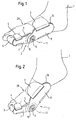
- FIG. 1 attached to a right foot 1 orthosis 2 is shown in a position in which the orthosis 2 is created by the fixable bandage 3 on the metatarsus 28 and also fixable bandage 4 on the big toe 5 in the normal position of the foot.
- the orthosis 2 is provided with the approximately located in its center joint 6, which divides the orthosis 2 in the toe leg 7 and the metatarsus 8.
- Both the toe leg 7 and the metatarsus 8 are provided on their side facing the foot with a padding 9 and 10, which ensure a complaint-free wearing of the brace 2.
- the two bandages 3 and 4 are known designs.
- the bandage 3 provides for the support of the midfoot leg 8 and the bandage 4 for the holder of the toe leg. 7
- the joint 6 allows the orthosis 2, when rolling the foot 1, as shown in Figure 2, the toes and thus the big toe 5 against the midfoot 28 to bend.
- the joint 6 has for this purpose a rotatable design, which will be discussed in more detail in connection with the figures 4 to 6.
- the effect as a pivot bearing is shown in Figures 1 and 2 by the drawn in the joint 6 dash-dotted line 11.
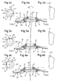
- the design of the joint 6 according to Figures 1 and 2 is shown in more detail in Figures 4 to 6, wherein various settings of the joint 6 are drawn.
- the joint 6 includes an adjustment ring 12, in which the ring bearing 13 for the metatarsus 8 are combined with the axle ring 14 for the toe leg 7.
- the adjusting ring 12 is for this purpose integrally connected to the axle ring 14 and the ring bearing 13.
- the merger Toe leg 7 and metatarsal 8 in the adjustment ring 12 takes place in that the respective leg on the respective storage, so axle ring 14 and ring bearing 13, are snapped, due to a corresponding elasticity of the adjustment ring 12 of the relevant overlapping edge recedes, the purpose is provided with an externally applied bevel, so that the two legs 7 and 8 can be connected to the adjusting ring 12 so that the adjusting ring 12, the two legs 7 and 8 fixed, but against the adjusting ring 12 rotatably holds.
- the adjusting ring 12 can be adjusted with respect to the Mittelfußschenkel 8 by rotation of the ring bearing 13 selectively, resulting in a respective pivoting angle of the toe leg 7 due to the eccentricity of ring bearing 13 to the axle ring 14 and an inclination of the plane of rotation 15 of the ring bearing 13 to the plane of rotation 16 of the axle ring 14 , as shown in the sequence of Figures 4 a, 5 a and 6 a, and of + 10 ° to an angle of -10 ° for the support of the toe leg 7, the case of a pointing away from the foot in Figure 4 b spread position 5 b is displaced over its normal position according to FIG. 5 b into a spread-in position directed towards the foot according to FIG. 6 b.
- This resulting displacement of the plane of rotation 15 results in the above-described adjustment of the toe leg 7, the thus pivoted due to its fixed abutment on the big toe 5 this in a corresponding position.
- the toe leg 7 is thereby pivoted accordingly (see the relevant grade information in Figures 4 b, 5 b and 6 b) and then retains this setting also, regardless of whether due to a flexion of the toes, a rotation of the adjusting ring 12 relative to the toe leg 7 results, which takes place in the region of the axle ring 14.
- the structure of the joint 6 is shown in an exploded view, wherein side by side of the midfoot leg 8 and the toe leg 7 is shown, which are held together with their aligned recesses 19 and 20.
- This is done by the adjusting ring 12, which consists of the ring bearing 13 and the axle ring 14.
- toe leg 7 and metatarsal 8 passes through the ring bearing 13, the recesses 20 and 19, until finally locked due to the elasticity of the individual ribs 21 of the ring bearing 13 behind the relevant edge of the recess 19 in the metatarsal leg 8, which said three parts are interconnected.
- the spreader ring 22 is provided, which fits into the bore in the ring bearing 13 and thereby pushes its individual ribs to the outside.
- the spreader ring 22 also ensures that a set angular position of the adjustment ring 12 remains secured to the metatarsus leg 8. This happens because in the recess 19 of the midfoot leg.
- 8 Vossprünge 23 are provided which engage in the gaps between the individual ribs 21 in the ring bearing 13. This engagement is achieved by removing the spreader ring 22, so that when the spreader ring 22 is removed, the setting of the adjusting ring 12, which is illustrated in connection with FIGS. 4, 5 and 6, can be made possible. After making the adjustment of the spreader ring 22 is then used, whereby the set Verschwenkungsgrad for the toe leg 7 is maintained.
- the orthosis according to the invention which is illustrated in the figures with reference to a right foot, can of course also be transferred to a left foot, in a sense mirror image of the orthosis is to be attached to a left foot, without changing the internal structure of the orthosis something.
- the apparent from Figures 4 c, 5 c and 6 c rotation of the adjusting ring 12 extends over the drawn in the figures upper part of the scale 18 and was thus based on a right foot.
- the lower part of the scale is used for the use of the scale, which to a certain extent is a mirror image of the upper part.
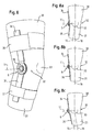
- FIGS. 8 and 8a to c show a further exemplary embodiment of the use of the orthosis according to the invention.
- It is a knee brace, which is applied to the thigh 30 and lower leg 31 of the leg, which contains the knee joint 32, to which the kneecap is indicated schematically by the reference numeral 33.
- the knee brace has the two legs 34 and 35, which are respectively strapped by the cuffs 36 and 37 formed fasteners on the thigh 30 and the lower leg 31.
- the cuffs are known designs.
- the two legs 34 and 35 are interconnected by the rotary joint 6, which corresponds completely to the pivot bearing 6 according to Figures 1 to 7 in terms of its internal configuration.
- FIGS. 4 a, 4 c, 5 a, 5 c, 6 a, 6 c With regard to the flexion movement of the knee joint 32 and the respective lateral pivoting of the knee joint 32, reference is made to the illustrations in FIGS. 4 a, 4 c, 5 a, 5 c, 6 a, 6 c.
- FIGS. 8a, 8b and 8c the planes of rotation 15 and 16 shown in FIGS. 4 a, 5 a and 6 a are also reproduced, but offset laterally in the direction of the center of the knee joint 32 8 c shown displacement results from a corresponding rotation of the twisted in the pivot 6 adjusting ring, whereby the position of the leg 35 relative to the leg 34 is adjusted accordingly, as a comparison of Figure 8 a and 8 c clearly shows.
- the plane of rotation 15 in the normal position according to FIG. 8 b coincides with the plane of rotation 16, which is responsible for the normal flexion movement of the knee joint 32.
Landscapes
- Health & Medical Sciences (AREA)
- Nursing (AREA)
- Orthopedic Medicine & Surgery (AREA)
- Engineering & Computer Science (AREA)
- Biomedical Technology (AREA)
- Heart & Thoracic Surgery (AREA)
- Vascular Medicine (AREA)
- Life Sciences & Earth Sciences (AREA)
- Animal Behavior & Ethology (AREA)
- General Health & Medical Sciences (AREA)
- Public Health (AREA)
- Veterinary Medicine (AREA)
- Orthopedics, Nursing, And Contraception (AREA)
- Prostheses (AREA)
- Rehabilitation Tools (AREA)
Claims (8)
- Orthèse (2) servant à corriger la position d'une articulation du corps, ladite orthèse s'étendant sur les deux membres (5, 28 ; 30, 31) reliés par l'articulation du corps et étant munie de deux plaques (7, 8 ; 34, 35) qui forment l'orthèse (2) et qui sont maintenues contre chacun des membres (5, 28 ; 30, 31) par un moyen de fixation (3, 4 ; 36, 37) et sont reliées entre elles par une articulation tournante (6) voisine de l'articulation du corps, caractérisée en ce que l'articulation tournante (6) assurant la flexion requise en déplacement normal est formée par une bague axiale (14) entourée par l'une des plaques (7, 35) et solidarisée à un palier annulaire (13) excentré par rapport à la bague axiale (14) pour former une bague centrale de réglage (12), ledit palier annulaire (13) formant un pivot destiné à l'autre plaque (8, 34) et entouré par celle-ci, et son plan de rotation (15) pouvant pivoter par rapport au plan de rotation (16) de la bague axiale (14) en tournant la bague de réglage (12) d'un angle tel que, en fonction de l'angle de rotation de la bague de réglage (12), la plaque (7, 35) portée par la bague axiale (14) et, avec elle, le membre (5, 31) maintenu par celle-ci adoptent, par rapport à la plaque (8, 34) reliée au palier annulaire (13), une position de pivotement de ce membre (5, 31) par rapport à la position normale tendue.
- Orthèse selon la revendication 1 pour corriger la position du gros orteil (5), comprenant deux plaques (7, 8) qui, à l'état appliqué, s'étendent du métatarse (28) au gros orteil (5) contre la face interne du pied (1) et sont chacune maintenues contre le métatarse (28) et contre le gros orteil (5) par un manchon (3, 4).
- Orthèse selon la revendication 1 pour corriger la position de l'articulation du genou (32), comprenant deux plaques (34, 35) qui, à l'état appliqué, s'étendent de la cuisse (30) à la jambe (31) en passant par l'articulation du genou (32), sont chacune maintenues contre 1a cuisse (30) et la jambe (31) par l'intermédiaire d'un manchon (36, 37) et sont reliées entre elles par l'intermédiaire d'une articulation tournante (6) voisine de l'articulation du genou (32).
- Orthèse selon une des revendications 1 à 3, caractérisée en ce que la plaque (7, 35) entourant 1a bague axiale (14) est munie d'une graduation annulaire (18) qui indique l'angle de rotation du palier annulaire (13) et ainsi la position de pivotement de l'autre plaque (8, 34).
- Orthèse selon une des revendications 1 à 4, caractérisée en ce que la liaison articulée des deux plaques (7, 8 ; 34, 35) et de la bague de réglage (12) est sécurisée par une bague d'écartement (22) enfoncée dans la bague axiale.
- Orthèse selon une des revendications 1 à 5, caractérisée en ce que la plaque (7, 35) entourant la bague axiale (14) est munie d'un moyen de blocage en rotation (24) pouvant être mis en place de manière quelconque.
- Orthèse selon une des revendications 1 à 6, caractérisée en ce que, sur leur côté tourné vers le membre, les plaques (7, 8 ; 34, 35) sont pourvues d'un rembourrage (9, 10).
- Orthèse selon une des revendications 1 à 7, caractérisée en ce que la bague axiale (14) et le palier annulaire (13) sont réalisés d'un seul tenant.
Applications Claiming Priority (2)
| Application Number | Priority Date | Filing Date | Title |
|---|---|---|---|
| DE102004008909A DE102004008909A1 (de) | 2004-02-24 | 2004-02-24 | Orthese zur Korrektur der Stellung eines Körpergelenks |
| DE102004008909 | 2004-02-24 |
Publications (2)
| Publication Number | Publication Date |
|---|---|
| EP1568337A1 EP1568337A1 (fr) | 2005-08-31 |
| EP1568337B1 true EP1568337B1 (fr) | 2006-11-15 |
Family
ID=34745259
Family Applications (1)
| Application Number | Title | Priority Date | Filing Date |
|---|---|---|---|
| EP05003742A Active EP1568337B1 (fr) | 2004-02-24 | 2005-02-22 | Orthèse pour la correction de la position d'une articulation anatomique |
Country Status (7)
| Country | Link |
|---|---|
| US (1) | US7322951B2 (fr) |
| EP (1) | EP1568337B1 (fr) |
| JP (1) | JP4660225B2 (fr) |
| CN (1) | CN100428921C (fr) |
| AT (1) | ATE345102T1 (fr) |
| DE (2) | DE102004008909A1 (fr) |
| ES (1) | ES2273292T3 (fr) |
Cited By (1)
| Publication number | Priority date | Publication date | Assignee | Title |
|---|---|---|---|---|
| DE102008009273A1 (de) | 2008-02-15 | 2009-08-20 | Bauerfeind Ag | Orthese zur Korrektur der Stellung eines Körpergelenks |
Families Citing this family (32)
| Publication number | Priority date | Publication date | Assignee | Title |
|---|---|---|---|---|
| DE102005035106A1 (de) * | 2005-07-27 | 2007-02-01 | Ps-Design+Prototyping Gmbh & Co. Kg | Orthese |
| DE102006019858A1 (de) * | 2006-04-28 | 2007-10-31 | Bauerfeind Ag | Knieprothesengelenk |
| DE202008004214U1 (de) * | 2008-03-27 | 2009-08-13 | Hallufix Ag | Orthopädische Vorrichtung zur Korrektur von Zehenfehlstellungen |
| DE102008049854B4 (de) | 2008-10-01 | 2013-07-25 | Albrecht Gmbh | Orthese zur Korrektur von Fehlstellungen und zum Redressieren von Körpergliedern in Abduktions- oder Adduktionsrichtung |
| US8111809B2 (en) * | 2009-01-29 | 2012-02-07 | The Invention Science Fund I, Llc | Diagnostic delivery service |
| US8130904B2 (en) * | 2009-01-29 | 2012-03-06 | The Invention Science Fund I, Llc | Diagnostic delivery service |
| JP5302111B2 (ja) * | 2009-06-09 | 2013-10-02 | 悦蔵 福田 | 外反母趾矯正具 |
| US9414952B2 (en) * | 2009-10-06 | 2016-08-16 | Dynasplint Systems, Inc. | Device for treating hallux varus |
| WO2011086716A1 (fr) * | 2010-01-15 | 2011-07-21 | 独立行政法人科学技術振興機構 | Dispositif de correction de valgus du gros orteil et procédé de fabrication du dispositif de correction de valgus du gros orteil |
| GB2477281B (en) * | 2010-01-27 | 2012-04-04 | Meditex Ltd | Podiatric device |
| JP5185458B1 (ja) * | 2012-06-29 | 2013-04-17 | 恒子 望月 | 変形性膝関節症矯正兼歩行補助具 |
| CN102824244B (zh) * | 2012-08-31 | 2014-02-12 | 邹旭 | 无创动态指骨牵引支具 |
| JP6241180B2 (ja) * | 2013-10-01 | 2017-12-06 | セイコーエプソン株式会社 | 指アシスト装置 |
| CA2926018A1 (fr) * | 2013-10-07 | 2015-04-16 | Albert CIESIELSKI | Dispositif orthopedique pour la correction d'hallux valgus |
| US11793660B2 (en) * | 2013-12-12 | 2023-10-24 | Yoel Schlesinger | Emergency limb fixation or restraining device |
| CN104887364B (zh) * | 2014-03-03 | 2018-11-02 | 精工爱普生株式会社 | 指关节驱动装置 |
| JP6432140B2 (ja) * | 2014-03-19 | 2018-12-05 | セイコーエプソン株式会社 | 指関節駆動装置 |
| WO2017041136A1 (fr) * | 2015-09-07 | 2017-03-16 | Anodynic Pty Ltd | Attelle orthopédique de bursite des orteils |
| ITUB20155355A1 (it) * | 2015-10-30 | 2017-04-30 | Fgp Srl | Snodo eccentrico tensionatore per ortesi o tutori ortopedici adibiti alla riabilitazione di articolazioni |
| DE102016212760B4 (de) | 2016-02-19 | 2021-09-09 | Fraunhofer-Gesellschaft zur Förderung der angewandten Forschung e.V. | Vorrichtung zur Prävention oder Behandlung einer Schiefstellung eines großen Zehens einer Person |
| DE102016216862A1 (de) * | 2016-09-06 | 2018-03-08 | Bauerfeind Ag | Kippbare Orthesengelenkschiene |
| KR102047331B1 (ko) * | 2017-10-19 | 2019-11-21 | 이휘경 | 엄지 발가락 교정구 |
| CN108992225A (zh) * | 2018-06-20 | 2018-12-14 | 深圳市福尔泰医疗科技有限公司 | 万向马蹄足矫形器 |
| CN109044585B (zh) * | 2018-08-28 | 2020-11-24 | 黄鑫 | 一种轻便型跟腱靴 |
| TWI698218B (zh) * | 2018-11-08 | 2020-07-11 | 施萬喜 | 關節變形之矯正裝置 |
| DE102019130391A1 (de) * | 2019-11-11 | 2021-05-12 | Ottobock Se & Co. Kgaa | Orthopädietechnische einrichtung |
| CN111728753A (zh) * | 2020-07-28 | 2020-10-02 | 杜伟 | 一种新型拇指外翻矫正器 |
| CN214342831U (zh) * | 2020-11-30 | 2021-10-08 | 杭州懒师兄健康科技有限公司 | 一种可调节脚趾矫正器 |
| KR102458544B1 (ko) * | 2020-12-30 | 2022-10-24 | 호원대학교산학협력단 | 무지외반증 다이얼 교정기 |
| DE102021107084A1 (de) | 2021-03-22 | 2022-09-22 | Hallufix Ag | Fussorthese mit drehgelenk zur korrektur von fussfehlstellungen |
| MX2021013324A (es) * | 2021-10-29 | 2023-05-01 | Paola Aralid Izaguirre Perez | Dispositivo correctivo de ajuste pasivo, gradual y progresivo, para el tratamiento del pie equino varo. |
| WO2023123717A1 (fr) * | 2021-12-28 | 2023-07-06 | 马庆利 | Correcteur orthétique de l'hallux valgus pouvant être librement plié et ajusté pour une utilisation |
Family Cites Families (26)
| Publication number | Priority date | Publication date | Assignee | Title |
|---|---|---|---|---|
| US1183062A (en) * | 1915-09-27 | 1916-05-16 | William H De Ford | Bunion-guard. |
| US3671978A (en) * | 1971-08-09 | 1972-06-27 | Hanger & Co Ltd J E | Angular adjustment devices for use in artificial limb manufacture |
| US4088129A (en) * | 1976-11-15 | 1978-05-09 | Digiulio Mario | Appliance for foot orthosis |
| US4256097A (en) * | 1978-12-29 | 1981-03-17 | Willis Robert E | Orthopedic apparatus for protecting and supporting a bone joint |
| US4353361A (en) * | 1980-08-25 | 1982-10-12 | Foster Robert W | Orthotic/prosthetic joint |
| CN87212005U (zh) * | 1987-08-19 | 1988-04-27 | 合肥市第一人民医院 | 有限制动多功能髋关节矫形器 |
| US4944290A (en) * | 1988-08-09 | 1990-07-31 | Dynasplint Systems, Inc. | Adjustable splint |
| US5086760A (en) * | 1989-04-14 | 1992-02-11 | Neumann Holm W | Articulated orthotic brace for an anatomical joint |
| JPH0322256U (fr) * | 1989-07-13 | 1991-03-07 | ||
| JPH07163609A (ja) * | 1991-05-06 | 1995-06-27 | Smith & Nephew Richards Inc | 動的関節支持器およびその固定方法 |
| US5244455A (en) * | 1991-07-19 | 1993-09-14 | Clinitex Corporation | Knee hinge |
| ES2044818T3 (es) * | 1992-04-29 | 1995-09-01 | Bock Orthopaed Ind | Ortesis para la articulacion de la rodilla. |
| US5437619A (en) * | 1993-06-30 | 1995-08-01 | Empi, Inc. | Range-of-motion splint with eccentric spring |
| US5658243A (en) * | 1995-08-28 | 1997-08-19 | Boston Brace International, Inc. | Knee brace |
| US5766140A (en) * | 1996-05-01 | 1998-06-16 | Smith & Nephew Donjoy, Inc. | Angular compensation device for a joint brace |
| DE19637728A1 (de) * | 1996-09-16 | 1998-03-26 | Bauerfeind Gmbh | Kniegelenkorthese |
| DE29705958U1 (de) * | 1997-04-04 | 1998-07-30 | Angerer, Manfred, 97421 Schweinfurt | Orthopädische sphärische Kniegelenkentlastungsstütze |
| US6090057A (en) * | 1998-01-20 | 2000-07-18 | Wonderful Widget Works, Ltd. | Multi-axial external orthotic joint |
| CA2241575A1 (fr) * | 1998-06-23 | 1999-12-23 | Devin J. Ostrom | Raccord et prothese incorporant celui-ci |
| US6027466A (en) * | 1998-09-04 | 2000-02-22 | Diefenbacher; Beat | Adjustable orthopedic device joint |
| US6254559B1 (en) * | 1999-08-30 | 2001-07-03 | Anthony C. Tyrrell | Adjustable hip joint assembly |
| CA2386905C (fr) * | 1999-12-21 | 2008-10-07 | Dj Orthopedics, Llc | Ensemble charniere pour une orthese orthopedique du genou et orthese du genou comprenant cet ensemble charniere |
| US6993808B1 (en) * | 2000-09-18 | 2006-02-07 | Lenjoy Medical Engineering, Inc. | Adjustable hinges for orthopedic splints |
| US6865523B2 (en) * | 2001-06-07 | 2005-03-08 | The United States Of America As Represented By The Secretary Of The Navy | Non-linear axisymmetric potential flow boundary model for partially cavitating high speed bodies |
| GB2382778B (en) * | 2001-12-07 | 2005-02-16 | Blatchford & Sons Ltd | An orthotic strut component |
| DE10240121B4 (de) * | 2002-08-30 | 2010-09-02 | Vitus Maria Huber | Orthopädische Vorrichtung zur Korrektur von Zehenfehlstellungen |
-
2004
- 2004-02-24 DE DE102004008909A patent/DE102004008909A1/de not_active Withdrawn
-
2005
- 2005-02-21 JP JP2005043575A patent/JP4660225B2/ja active Active
- 2005-02-22 AT AT05003742T patent/ATE345102T1/de not_active IP Right Cessation
- 2005-02-22 ES ES05003742T patent/ES2273292T3/es active Active
- 2005-02-22 DE DE502005000176T patent/DE502005000176D1/de active Active
- 2005-02-22 EP EP05003742A patent/EP1568337B1/fr active Active
- 2005-02-23 US US11/063,863 patent/US7322951B2/en active Active
- 2005-02-23 CN CNB200510067715XA patent/CN100428921C/zh active Active
Cited By (1)
| Publication number | Priority date | Publication date | Assignee | Title |
|---|---|---|---|---|
| DE102008009273A1 (de) | 2008-02-15 | 2009-08-20 | Bauerfeind Ag | Orthese zur Korrektur der Stellung eines Körpergelenks |
Also Published As
| Publication number | Publication date |
|---|---|
| CN1666721A (zh) | 2005-09-14 |
| ES2273292T3 (es) | 2007-05-01 |
| CN100428921C (zh) | 2008-10-29 |
| ATE345102T1 (de) | 2006-12-15 |
| US20050187506A1 (en) | 2005-08-25 |
| JP2005237962A (ja) | 2005-09-08 |
| DE502005000176D1 (de) | 2006-12-28 |
| DE102004008909A1 (de) | 2005-09-08 |
| EP1568337A1 (fr) | 2005-08-31 |
| US7322951B2 (en) | 2008-01-29 |
| JP4660225B2 (ja) | 2011-03-30 |
Similar Documents
| Publication | Publication Date | Title |
|---|---|---|
| EP1568337B1 (fr) | Orthèse pour la correction de la position d'une articulation anatomique | |
| DE68928511T2 (de) | Knieorthese mit gesteuerter Mehrachsenbewegung | |
| DE112012004113B4 (de) | Orthese zur Korrektur von Oberarmfrakturen | |
| EP0913132B1 (fr) | Prothèse de genou | |
| EP0880346B1 (fr) | Orthese du genou | |
| DE10259751B4 (de) | Vorrichtung zum Aufbringen einer ventral oder dorsal gerichteten Translationskraft im Kniegelenksbereich | |
| EP2524672B1 (fr) | Articulation pour soutiens, orthèses ou prothèses du genou | |
| DE2528583A1 (de) | Geraet zur chirurgischen behandlung von knochen und gelenken | |
| DE202011004130U1 (de) | Orthesengelenk mit zwei Funktionsmitteln zum Bilden eines federnden Dorsalanschlags und eines federnden Plantaranschlags | |
| DE2063547A1 (de) | Ellenbogengelenkprothese | |
| EP1479360B1 (fr) | Attelle orthopédique | |
| DE102008049854B4 (de) | Orthese zur Korrektur von Fehlstellungen und zum Redressieren von Körpergliedern in Abduktions- oder Adduktionsrichtung | |
| AT517182B1 (de) | Führungsgelenk für eine Gelenksorthese | |
| EP0705582B1 (fr) | Orthèse de l'articulation du genou | |
| DE102010049189A1 (de) | Dynamische Schultergelenksorthese, insbesondere Schulterabduktionsorthese | |
| DE102016107779A1 (de) | Orthesengelenk, Baukastensystem zur Bildung eines Orthesengelenkes und Verwendung dessen | |
| EP3085343B1 (fr) | Orthese de reeducation de cheville | |
| DE1147711B (de) | Abduktionsschiene | |
| DE102014114430A1 (de) | Orthesengelenk | |
| DE69332170T2 (de) | Gerät zur behandlung von thoraxdeformierungen wie skoliose | |
| DE19933197B4 (de) | Polyzentrische Gelenkstütze mit Zahnrad-Verstellmechanismus für die stufenlose Feinverstellung einer Schwenkbereichsgrenze | |
| EP4212134B1 (fr) | Orthèse de cheville | |
| DE202005010491U1 (de) | Orthopädische Vorrichtung zur Korrektur von Zehenfehlstellungen | |
| DE102009056321A1 (de) | Orthesengelenk | |
| DE102022128396A1 (de) | Orthopädietechnische Einrichtung mit pivotierender Drehachse |
Legal Events
| Date | Code | Title | Description |
|---|---|---|---|
| PUAI | Public reference made under article 153(3) epc to a published international application that has entered the european phase |
Free format text: ORIGINAL CODE: 0009012 |
|
| AK | Designated contracting states |
Kind code of ref document: A1 Designated state(s): AT BE BG CH CY CZ DE DK EE ES FI FR GB GR HU IE IS IT LI LT LU MC NL PL PT RO SE SI SK TR |
|
| AX | Request for extension of the european patent |
Extension state: AL BA HR LV MK YU |
|
| 17P | Request for examination filed |
Effective date: 20060227 |
|
| AKX | Designation fees paid |
Designated state(s): AT BE BG CH CY CZ DE DK EE ES FI FR GB GR HU IE IS IT LI LT LU MC NL PL PT RO SE SI SK TR |
|
| GRAP | Despatch of communication of intention to grant a patent |
Free format text: ORIGINAL CODE: EPIDOSNIGR1 |
|
| GRAS | Grant fee paid |
Free format text: ORIGINAL CODE: EPIDOSNIGR3 |
|
| GRAA | (expected) grant |
Free format text: ORIGINAL CODE: 0009210 |
|
| AK | Designated contracting states |
Kind code of ref document: B1 Designated state(s): AT BE BG CH CY CZ DE DK EE ES FI FR GB GR HU IE IS IT LI LT LU MC NL PL PT RO SE SI SK TR |
|
| PG25 | Lapsed in a contracting state [announced via postgrant information from national office to epo] |
Ref country code: PL Free format text: LAPSE BECAUSE OF FAILURE TO SUBMIT A TRANSLATION OF THE DESCRIPTION OR TO PAY THE FEE WITHIN THE PRESCRIBED TIME-LIMIT Effective date: 20061115 Ref country code: CZ Free format text: LAPSE BECAUSE OF FAILURE TO SUBMIT A TRANSLATION OF THE DESCRIPTION OR TO PAY THE FEE WITHIN THE PRESCRIBED TIME-LIMIT Effective date: 20061115 Ref country code: NL Free format text: LAPSE BECAUSE OF FAILURE TO SUBMIT A TRANSLATION OF THE DESCRIPTION OR TO PAY THE FEE WITHIN THE PRESCRIBED TIME-LIMIT Effective date: 20061115 Ref country code: FI Free format text: LAPSE BECAUSE OF FAILURE TO SUBMIT A TRANSLATION OF THE DESCRIPTION OR TO PAY THE FEE WITHIN THE PRESCRIBED TIME-LIMIT Effective date: 20061115 Ref country code: SI Free format text: LAPSE BECAUSE OF FAILURE TO SUBMIT A TRANSLATION OF THE DESCRIPTION OR TO PAY THE FEE WITHIN THE PRESCRIBED TIME-LIMIT Effective date: 20061115 Ref country code: RO Free format text: LAPSE BECAUSE OF FAILURE TO SUBMIT A TRANSLATION OF THE DESCRIPTION OR TO PAY THE FEE WITHIN THE PRESCRIBED TIME-LIMIT Effective date: 20061115 Ref country code: IE Free format text: LAPSE BECAUSE OF FAILURE TO SUBMIT A TRANSLATION OF THE DESCRIPTION OR TO PAY THE FEE WITHIN THE PRESCRIBED TIME-LIMIT Effective date: 20061115 Ref country code: LT Free format text: LAPSE BECAUSE OF FAILURE TO SUBMIT A TRANSLATION OF THE DESCRIPTION OR TO PAY THE FEE WITHIN THE PRESCRIBED TIME-LIMIT Effective date: 20061115 Ref country code: SK Free format text: LAPSE BECAUSE OF FAILURE TO SUBMIT A TRANSLATION OF THE DESCRIPTION OR TO PAY THE FEE WITHIN THE PRESCRIBED TIME-LIMIT Effective date: 20061115 |
|
| REG | Reference to a national code |
Ref country code: GB Ref legal event code: FG4D Free format text: NOT ENGLISH |
|
| GBT | Gb: translation of ep patent filed (gb section 77(6)(a)/1977) |
Effective date: 20061115 |
|
| REG | Reference to a national code |
Ref country code: CH Ref legal event code: EP Ref country code: CH Ref legal event code: NV Representative=s name: A. BRAUN, BRAUN, HERITIER, ESCHMANN AG PATENTANWAE |
|
| REF | Corresponds to: |
Ref document number: 502005000176 Country of ref document: DE Date of ref document: 20061228 Kind code of ref document: P |
|
| REG | Reference to a national code |
Ref country code: IE Ref legal event code: FG4D Free format text: LANGUAGE OF EP DOCUMENT: GERMAN |
|
| PG25 | Lapsed in a contracting state [announced via postgrant information from national office to epo] |
Ref country code: DK Free format text: LAPSE BECAUSE OF FAILURE TO SUBMIT A TRANSLATION OF THE DESCRIPTION OR TO PAY THE FEE WITHIN THE PRESCRIBED TIME-LIMIT Effective date: 20070215 Ref country code: BG Free format text: LAPSE BECAUSE OF FAILURE TO SUBMIT A TRANSLATION OF THE DESCRIPTION OR TO PAY THE FEE WITHIN THE PRESCRIBED TIME-LIMIT Effective date: 20070215 |
|
| REG | Reference to a national code |
Ref country code: SE Ref legal event code: TRGR |
|
| PG25 | Lapsed in a contracting state [announced via postgrant information from national office to epo] |
Ref country code: MC Free format text: LAPSE BECAUSE OF NON-PAYMENT OF DUE FEES Effective date: 20070228 |
|
| PG25 | Lapsed in a contracting state [announced via postgrant information from national office to epo] |
Ref country code: IS Free format text: LAPSE BECAUSE OF FAILURE TO SUBMIT A TRANSLATION OF THE DESCRIPTION OR TO PAY THE FEE WITHIN THE PRESCRIBED TIME-LIMIT Effective date: 20070315 |
|
| PG25 | Lapsed in a contracting state [announced via postgrant information from national office to epo] |
Ref country code: PT Free format text: LAPSE BECAUSE OF FAILURE TO SUBMIT A TRANSLATION OF THE DESCRIPTION OR TO PAY THE FEE WITHIN THE PRESCRIBED TIME-LIMIT Effective date: 20070416 |
|
| NLV1 | Nl: lapsed or annulled due to failure to fulfill the requirements of art. 29p and 29m of the patents act | ||
| REG | Reference to a national code |
Ref country code: ES Ref legal event code: FG2A Ref document number: 2273292 Country of ref document: ES Kind code of ref document: T3 |
|
| ET | Fr: translation filed | ||
| REG | Reference to a national code |
Ref country code: IE Ref legal event code: FD4D |
|
| PLBE | No opposition filed within time limit |
Free format text: ORIGINAL CODE: 0009261 |
|
| STAA | Information on the status of an ep patent application or granted ep patent |
Free format text: STATUS: NO OPPOSITION FILED WITHIN TIME LIMIT |
|
| 26N | No opposition filed |
Effective date: 20070817 |
|
| BERE | Be: lapsed |
Owner name: BAUERFEIND A.G. Effective date: 20070228 |
|
| PG25 | Lapsed in a contracting state [announced via postgrant information from national office to epo] |
Ref country code: BE Free format text: LAPSE BECAUSE OF NON-PAYMENT OF DUE FEES Effective date: 20070228 |
|
| PG25 | Lapsed in a contracting state [announced via postgrant information from national office to epo] |
Ref country code: GR Free format text: LAPSE BECAUSE OF FAILURE TO SUBMIT A TRANSLATION OF THE DESCRIPTION OR TO PAY THE FEE WITHIN THE PRESCRIBED TIME-LIMIT Effective date: 20070216 |
|
| REG | Reference to a national code |
Ref country code: CH Ref legal event code: PFA Owner name: BAUERFEIND AG Free format text: BAUERFEIND AG#TRIEBESER STRASSE 16#07937 ZEULENRODA (DE) -TRANSFER TO- BAUERFEIND AG#TRIEBESER STRASSE 16#07937 ZEULENRODA (DE) |
|
| PG25 | Lapsed in a contracting state [announced via postgrant information from national office to epo] |
Ref country code: AT Free format text: LAPSE BECAUSE OF NON-PAYMENT OF DUE FEES Effective date: 20070222 |
|
| PG25 | Lapsed in a contracting state [announced via postgrant information from national office to epo] |
Ref country code: EE Free format text: LAPSE BECAUSE OF FAILURE TO SUBMIT A TRANSLATION OF THE DESCRIPTION OR TO PAY THE FEE WITHIN THE PRESCRIBED TIME-LIMIT Effective date: 20061115 |
|
| PG25 | Lapsed in a contracting state [announced via postgrant information from national office to epo] |
Ref country code: CY Free format text: LAPSE BECAUSE OF FAILURE TO SUBMIT A TRANSLATION OF THE DESCRIPTION OR TO PAY THE FEE WITHIN THE PRESCRIBED TIME-LIMIT Effective date: 20061115 Ref country code: LU Free format text: LAPSE BECAUSE OF NON-PAYMENT OF DUE FEES Effective date: 20070222 |
|
| PG25 | Lapsed in a contracting state [announced via postgrant information from national office to epo] |
Ref country code: HU Free format text: LAPSE BECAUSE OF FAILURE TO SUBMIT A TRANSLATION OF THE DESCRIPTION OR TO PAY THE FEE WITHIN THE PRESCRIBED TIME-LIMIT Effective date: 20070516 Ref country code: TR Free format text: LAPSE BECAUSE OF FAILURE TO SUBMIT A TRANSLATION OF THE DESCRIPTION OR TO PAY THE FEE WITHIN THE PRESCRIBED TIME-LIMIT Effective date: 20061115 |
|
| REG | Reference to a national code |
Ref country code: CH Ref legal event code: PCAR Free format text: NEW ADDRESS: HOLBEINSTRASSE 36-38, 4051 BASEL (CH) |
|
| REG | Reference to a national code |
Ref country code: FR Ref legal event code: PLFP Year of fee payment: 12 |
|
| REG | Reference to a national code |
Ref country code: FR Ref legal event code: PLFP Year of fee payment: 13 |
|
| REG | Reference to a national code |
Ref country code: FR Ref legal event code: PLFP Year of fee payment: 14 |
|
| P01 | Opt-out of the competence of the unified patent court (upc) registered |
Effective date: 20230629 |
|
| PGFP | Annual fee paid to national office [announced via postgrant information from national office to epo] |
Ref country code: ES Payment date: 20240319 Year of fee payment: 20 |
|
| PGFP | Annual fee paid to national office [announced via postgrant information from national office to epo] |
Ref country code: DE Payment date: 20240228 Year of fee payment: 20 Ref country code: CH Payment date: 20240301 Year of fee payment: 20 Ref country code: GB Payment date: 20240222 Year of fee payment: 20 |
|
| PGFP | Annual fee paid to national office [announced via postgrant information from national office to epo] |
Ref country code: SE Payment date: 20240221 Year of fee payment: 20 Ref country code: IT Payment date: 20240229 Year of fee payment: 20 Ref country code: FR Payment date: 20240222 Year of fee payment: 20 |