EP1567905B1 - Verbesserter brillenbügel - Google Patents
Verbesserter brillenbügel Download PDFInfo
- Publication number
- EP1567905B1 EP1567905B1 EP03797041A EP03797041A EP1567905B1 EP 1567905 B1 EP1567905 B1 EP 1567905B1 EP 03797041 A EP03797041 A EP 03797041A EP 03797041 A EP03797041 A EP 03797041A EP 1567905 B1 EP1567905 B1 EP 1567905B1
- Authority
- EP
- European Patent Office
- Prior art keywords
- region
- temple
- temple piece
- improved
- piece
- Prior art date
- Legal status (The legal status is an assumption and is not a legal conclusion. Google has not performed a legal analysis and makes no representation as to the accuracy of the status listed.)
- Expired - Lifetime
Links
- 235000019589 hardness Nutrition 0.000 claims description 11
- 239000000463 material Substances 0.000 claims description 11
- 239000003086 colorant Substances 0.000 claims description 2
- 238000002347 injection Methods 0.000 claims 1
- 239000007924 injection Substances 0.000 claims 1
- 230000009977 dual effect Effects 0.000 description 10
- 210000003128 head Anatomy 0.000 description 9
- 238000001746 injection moulding Methods 0.000 description 3
- 210000005069 ears Anatomy 0.000 description 2
- 210000004761 scalp Anatomy 0.000 description 2
- 239000000126 substance Substances 0.000 description 2
- 239000000853 adhesive Substances 0.000 description 1
- 230000001070 adhesive effect Effects 0.000 description 1
- 230000000694 effects Effects 0.000 description 1
- 238000012986 modification Methods 0.000 description 1
- 230000004048 modification Effects 0.000 description 1
- 239000007779 soft material Substances 0.000 description 1
- 230000000087 stabilizing effect Effects 0.000 description 1
Images

Classifications
-
- G—PHYSICS
- G02—OPTICS
- G02C—SPECTACLES; SUNGLASSES OR GOGGLES INSOFAR AS THEY HAVE THE SAME FEATURES AS SPECTACLES; CONTACT LENSES
- G02C5/00—Constructions of non-optical parts
Definitions
- temples typically mount to an eyeglass frame, or directly to the lens of an eyewear piece.
- Temples also extend from the eyewear lens or frame rearwardly along the sides of the wearer's head (generally past the temple region of the head and past or around the ears.
- temples By extending along the sides of a wearer's head, temples provide a stabilizing member for support of the eyewear as it rests on the nose of a wearer.
- Temples may also provide additional points of support for the eyewear where such temples apply some pressure inwardly towards the side of the wearer's head and/or where such temples rest on top of the wearer's ears.
- the presently described, improved temple piece for eyewear generally includes dual regions at various positions along the length thereof, the dual regions having different levels of hardness.
- a relatively soft region extends substantially along the length of the temple.
- the relatively hard region may extend the entire length of the temple, or it may extend only a portion of the length of the temple.
- the relatively soft region extends substantially along the length of the temple, but terminates within between about one to two inches from the end of the temple piece. In another embodiment, the relatively soft region extends substantially along the length of the temple, but does not run to the end of the attachment portion and does not run to the opposing end of the temple piece.
- the relatively soft region is located such that the relatively soft region would rest on the top of a wearer's ear, but is also positioned such that the relatively soft region does not predominantly contact the side of the wearer's head (and thus, does not grip the wearer's hair, scalp or temple).
- the temple which includes dual regions at various positions along the length thereof, the dual regions having different levels of hardness, is formed during a dual injection molding process.
- FIGURE 1 depicts a bottom view of an exemplary temple in accordance with the present disclosure
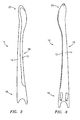
- FIGURE 2 depicts an exterior side view of the exemplary temple of FIGURE 1 ;
- FIGURE 3 depicts an interior side view of the exemplary temple of FIGURE 1 .
- the presently described, improved temple piece for eyewear generally includes dual regions at various positions along the length thereof, the dual regions having different levels of hardness.
- an exemplary improved temple piece for eyewear is shown generally at 10.
- the exemplary temple piece 10 includes; without limitation (i.e., multiple regions may be had, as long as there are at least two exposed regions having differing hardnesses), a first region 12 and a second region 14.
- the first region 12 generally has a lower level of hardness (i.e., is softer) than the second region 14.
- the temple piece 10 is shown generally with three portions, an attachment portion 16, a side length portion 18, and an end portion 20.
- the first region extends substantially along the length of the exemplary temple. It should be noted that while first region 12 is not illustrated to run the entire lengths of the attachment portion 16 and the end portion 20, the first region 12 may optionally run the full lengths of those portions. Additionally, while the first region 12 is illustrated as running the entire length of the side length portion 18, the first region 12 may optionally run less than the whole length of the side length portion 18 and still run substantially along the length of the exemplary temple. Also, while a particular length is illustrated in the exemplary example, such particular length is not to be limiting. Indeed, the overall length may be somewhat more or less than the length illustrated by the exemplary temple of FIGURE 1 and still be equivalent.
- FIGURE 2 a side view of the exemplary temple of FIGURE 1 is illustrated.
- the illustrated temple is configured to engage the left side of eyewear.
- the first region 12 is disposed at least partially on the lower edge of the outside of the temple.
- the first region 12 does not extend beyond the vertical axis onto the interior surface of the exemplary temple.
- the above-described embodiments predominantly dispose the harder second region 14 in proximity to the sides of a wearer's head, and dispose in at least one of the side length portion 18 and the end portion 20, the softer material of the first region 12 at least on the lower edge of the temple.
- Such an arrangement advantageously places the softer region in areas that will grip the ear and optionally a small portion of the head that attaches to the ear.
- Such an arrangement also excludes the softer regions from areas proximate to the side of the head, thereby preventing the scalp and hair of the wearer from being gripped and/or pulled by the softer, more tacky material of the first region 12, which may be particularly problematic during doffing or donning of the eyewear, or during activities that may tend to cause the eyewear to move back and forth on the wearer's head.
- the first region 12 may extend from the lower edge of the temple around at least a portion of the exterior surface of the temple, in at least one of the side length portion 18 and end portion 20.
- the first region 12 in at least one of the side length portion 18 and end portion 20, extends more than about 60 percent of the surface distance from the lower intersection of the vertical axis onto the exterior surface to the upper intersection of the vertical axis of the exemplary temple. In such embodiment, it may be particularly advantageous to position such first region 12 such that it extends at least from the saddle of the wearer's ear along the exterior of the temple such that it maximizes contact with the helix of the wearer's ear.
- the temple piece 10 with dual regions 12, 14 having differing levels of hardness is made in a single co-injection molding step (rather than being formed separately and thereafter bonded together).
- Such exemplary co-injection molding may permit substantial savings in processing time and in assembly time.
- the co-molded regions 12, 14 would remain bonded together either through a chemical bond (through proper selection of the co-molded materials) or through a mechanical bond. Additionally, the co-molded regions 12, 14 may bond through a combination of chemical and mechanical bonds.
- the dual regions 12, 14 may be separately fashioned and subsequently assembled, as is known in the art, e.g., by a mechanical interference fit or with the use of an adhesive.
- first region 12 and the second region 14 comprise materials having differing durometer hardnesses. Such arrangement facilitates strategic placement of these relatively hard and soft materials. Any variation in hardness is contemplated by the present disclosure. However, in one exemplary embodiment, the first region comprises about a 40 to 50 Shore A durometer material, while the second region comprises about an 80 to 90 Shore A durometer material. In another embodiment, additional regions are provided, wherein such additional regions comprise about 40 to 90 Shore A durometer materials.
- the dual regions 12, 14 are provided having different colors, such that the relative hard and soft regions of the temple may be visually distinguished.
Landscapes
- Physics & Mathematics (AREA)
- Health & Medical Sciences (AREA)
- General Physics & Mathematics (AREA)
- Ophthalmology & Optometry (AREA)
- Optics & Photonics (AREA)
- Eyeglasses (AREA)
Claims (12)
- Verbesserter Bügel, enthaltend:einen verlängerten Bügel (10) mit zumindest einem ersten Bereich (12) und einem zweiten Bereich (14), wobei der zumindest erste und zweite Bereich Materialien aufweisen, die unterschiedliche Shore-A Durometer-Härtegrade haben,wobei der erste Bereich (12) einen Shore-A Durometer-Härtegrad hat, der kleiner ist als der des zweiten Bereiches (14), und wobei sich der erste Bereich (12) entlang einer unteren Kante des Bügels (10) zumindest entlang eines mittleren oder nicht zur Befestigung bestimmten Endbereichs (20) des Bügels (10) erstreckt, dadurch gekennzeichnet, dass sich der erste Bereich nicht über die vertikale Achse auf die innenliegende Fläche des Bügels erstreckt, und dass sich der erste Bereich vorherrschend in zumindest einem Bügelbereich ausgehend von der unteren Kante über eine außenliegende Fläche des Bügels erstreckt, derart, dass der Kontakt zwischen dem ersten Bereich (12) und dem äußeren Rand der Ohrmuschel des Benutzers im Übrigen vergrößert wird.
- Verbesserter Bügel nach Anspruch 1, wobei sich der erste Bereich (12) über mindestens 75 Prozent der Länge des Bügels (10) erstreckt.
- Verbesserter Bügel nach Anspruch 1, wobei sich der erste Bereich (12) über mindestens 85 Prozent der Länge des Bügels (10) erstreckt.
- Verbesserter Bügel nach Anspruch 1, wobei sich der erste Bereich (12) über mindestens 95 Prozent der Länge des Bügels (10) erstreckt.
- Verbesserter Bügel nach Anspruch 1, wobei der erste Bereich (12) ein Material mit einem Shore-A Durometer-Härtegrad von ungefähr 40 bis 50 aufweist und wobei der zweite Bereich ein Material mit einem Shore-A Durometer-Härtegrad von ungefähr 80 bis 90 aufweist.
- Verbesserter Bügel nach Anspruch 1, wobei der erste Bereich (12) und der zweite Bereich (14) Materialien mit unterschiedlichen Farben aufweisen.
- Verbesserter Bügel nach Anspruch 1, wobei der erste Bereich und der zweite Bereich im Sandwichspritzgießverfahren hergestellt sind.
- Verbesserter Bügel nach Anspruch 1, wobei der erste Bereich sich, in zumindest einem der Bereiche, in denen sich der erste Bereich entlang der unteren Kante des Bügels erstreckt, nicht ausgehend von einer zusammengefügten vertikalen Achse des Bügels an der unteren Kante zu mehr als 25 Prozent über die außenliegende Fläche des Bügels erstreckt.
- Verbesserter Bügel nach Anspruch 1, wobei der erste Bereich sich, in zumindest einem der Bereiche, in denen sich der erste Bereich entlang der unteren Kante des Bügels erstreckt, nicht ausgehend von einer zusammengefügten vertikalen Achse des Bügels an der unteren Kante zu mehr als 12 Prozent über die außenliegende Fläche des Bügels erstreckt.
- Verbesserter Bügel nach Anspruch 1, wobei sich der erste Bereich im Wesentlichen über die Länge des Bügels erstreckt.
- Verbesserter Bügel nach Anspruch 1, wobei der erste Bereich sich, in zumindest einem der Bereiche, in denen sich der erste Bereich entlang der unteren Kante des Bügels erstreckt, ausgehend von einer zusammengefügten vertikalen Achse des Bügels an der unteren Kante zu mehr als 60 Prozent über die außenliegende Fläche des Bügels erstreckt.
- Verbesserter Bügel nach Anspruch 1, wobei der erste Bereich sich, in zumindest einem der Bereiche, in denen sich der erste Bereich entlang der unteren Kante des Bügels erstreckt, ausgehend von einer zusammengefügten vertikalen Achse des Bügels an der unteren Kante zu mehr als 75 Prozent über die außenliegende Fläche des Bügels erstreckt.
Applications Claiming Priority (3)
| Application Number | Priority Date | Filing Date | Title |
|---|---|---|---|
| US307615 | 1999-05-07 | ||
| US10/307,615 US7055952B2 (en) | 2002-12-02 | 2002-12-02 | Temple piece for eyewear |
| PCT/US2003/040057 WO2004051348A1 (en) | 2002-12-02 | 2003-12-02 | Improved temple piece for eyewear |
Publications (2)
| Publication Number | Publication Date |
|---|---|
| EP1567905A1 EP1567905A1 (de) | 2005-08-31 |
| EP1567905B1 true EP1567905B1 (de) | 2008-07-23 |
Family
ID=32392592
Family Applications (1)
| Application Number | Title | Priority Date | Filing Date |
|---|---|---|---|
| EP03797041A Expired - Lifetime EP1567905B1 (de) | 2002-12-02 | 2003-12-02 | Verbesserter brillenbügel |
Country Status (8)
| Country | Link |
|---|---|
| US (1) | US7055952B2 (de) |
| EP (1) | EP1567905B1 (de) |
| CN (1) | CN1717610A (de) |
| AU (1) | AU2003297969A1 (de) |
| CA (1) | CA2507508A1 (de) |
| DE (1) | DE60322421D1 (de) |
| RU (1) | RU2005120740A (de) |
| WO (1) | WO2004051348A1 (de) |
Families Citing this family (16)
| Publication number | Priority date | Publication date | Assignee | Title |
|---|---|---|---|---|
| JP2006184490A (ja) * | 2004-12-27 | 2006-07-13 | Yamamoto Kogaku Co Ltd | 眼鏡用モダン |
| DE102005034081A1 (de) * | 2005-07-21 | 2007-01-25 | Uvex Arbeitsschutz Gmbh | Verfahren zur Herstellung eines Brillenbügels |
| FR2894686B1 (fr) * | 2005-12-09 | 2008-02-22 | Logo Sa | Lunettes a branches multicouches, interchangeables. |
| USD548770S1 (en) * | 2006-05-05 | 2007-08-14 | Cartier Creation Studio Sa | Glasses |
| US7490935B1 (en) * | 2006-06-09 | 2009-02-17 | Revision Eyewear, Inc. | Overmolded spectacle arm extremities |
| US7452071B2 (en) * | 2006-07-14 | 2008-11-18 | Wolf Peak Holdings, Llc | Flexible temple for eyewear |
| USD597122S1 (en) | 2008-04-29 | 2009-07-28 | Wolf Peak Holdings, Inc. | Eyewear |
| USD599840S1 (en) | 2008-12-04 | 2009-09-08 | Wolf Peak Holdings, Inc. | Eyewear |
| USD606113S1 (en) | 2008-12-04 | 2009-12-15 | Wolf Peak Holdings, Inc. | Eyewear |
| US7878647B2 (en) * | 2009-04-09 | 2011-02-01 | Live Eyewear, Inc. | Frame for eyeglasses, associated temple, and method of making the same |
| USD620040S1 (en) | 2010-01-04 | 2010-07-20 | Wolf Peak Holdings, Inc. | Eyewear |
| JP5889801B2 (ja) * | 2010-01-08 | 2016-03-22 | オークリー インコーポレイテッド | アイウェアテンプル装置及び方法 |
| US9122079B2 (en) | 2012-09-28 | 2015-09-01 | Advanced Eye Protection IP Holding | Temple assembly for eyewear |
| US9067352B2 (en) | 2013-08-15 | 2015-06-30 | Optimeyes4U, Inc. | System and process for shot-injection molding an eyeglass temple with a wire core |
| US10588642B2 (en) * | 2014-05-15 | 2020-03-17 | Gauthier Biomedical, Inc. | Molding process and products formed thereby |
| US9855171B2 (en) * | 2015-03-04 | 2018-01-02 | 3R Products, Llc | Safety glasses |
Family Cites Families (7)
| Publication number | Priority date | Publication date | Assignee | Title |
|---|---|---|---|---|
| DE3319826A1 (de) | 1983-06-01 | 1984-12-06 | Marwitz & Hauser GmbH, 7000 Stuttgart | Buegelende von brillenbuegeln |
| US4955706A (en) | 1988-09-30 | 1990-09-11 | Optyl Eyewear Fashion International Corporation | Composite polymeric spectacle parts |
| JPH085963A (ja) | 1994-06-20 | 1996-01-12 | Nikon Corp | 眼鏡フレーム用セル |
| DE19547799C2 (de) | 1995-12-20 | 1997-11-27 | Wilhelm Anger | Bügelendstück |
| WO1999056942A1 (en) | 1998-05-07 | 1999-11-11 | Luxottica Leasing S.P.A. | Eyewear frame construction |
| US6059408A (en) * | 1999-07-13 | 2000-05-09 | Bonacci; Thomas A. | Snug fitting floating eyeglasses |
| US6565208B1 (en) * | 2002-06-06 | 2003-05-20 | Shu-Min Lee | Temple plate pad adapted to securely engage with a temple plate of a pair of eyeglasses |
-
2002
- 2002-12-02 US US10/307,615 patent/US7055952B2/en not_active Expired - Fee Related
-
2003
- 2003-12-02 EP EP03797041A patent/EP1567905B1/de not_active Expired - Lifetime
- 2003-12-02 DE DE60322421T patent/DE60322421D1/de not_active Expired - Lifetime
- 2003-12-02 CA CA002507508A patent/CA2507508A1/en not_active Abandoned
- 2003-12-02 WO PCT/US2003/040057 patent/WO2004051348A1/en not_active Ceased
- 2003-12-02 AU AU2003297969A patent/AU2003297969A1/en not_active Abandoned
- 2003-12-02 RU RU2005120740/28A patent/RU2005120740A/ru not_active Application Discontinuation
- 2003-12-02 CN CN200380104535.3A patent/CN1717610A/zh active Pending
Also Published As
| Publication number | Publication date |
|---|---|
| US20040105069A1 (en) | 2004-06-03 |
| US7055952B2 (en) | 2006-06-06 |
| EP1567905A1 (de) | 2005-08-31 |
| DE60322421D1 (de) | 2008-09-04 |
| CN1717610A (zh) | 2006-01-04 |
| WO2004051348A1 (en) | 2004-06-17 |
| RU2005120740A (ru) | 2006-01-20 |
| AU2003297969A1 (en) | 2004-06-23 |
| CA2507508A1 (en) | 2004-06-17 |
Similar Documents
| Publication | Publication Date | Title |
|---|---|---|
| US7055952B2 (en) | Temple piece for eyewear | |
| US8051502B2 (en) | Swimming goggles | |
| US7290294B2 (en) | Protective goggles | |
| WO2002052334A1 (fr) | Lunettes dotees d'un pare-vent, pare-vent pour lunettes et procede permettant de proteger des lunettes contre le vent | |
| JP6618158B2 (ja) | 眼鏡、及び眼鏡支持部材 | |
| JP3490326B2 (ja) | 水中眼鏡 | |
| US9703116B2 (en) | Eyeglass frames with flexible temples | |
| JPH1043231A (ja) | 工業用安全眼鏡 | |
| KR20210001806U (ko) | 수경 | |
| KR960001800A (ko) | 안경 프레임용 귀 걸이부 | |
| US7490934B2 (en) | Eyewear end piece | |
| JPH0151812B2 (de) | ||
| JPH11104267A (ja) | 水中メガネ | |
| KR101206752B1 (ko) | 들뜸 방지용 인조 팁네일 | |
| JP3689247B2 (ja) | 眼鏡フレーム用装飾リム及び装飾リムの装着方法 | |
| US7431452B2 (en) | Lens attachment to eyewear having cushion pad | |
| WO2019220682A1 (ja) | 眼鏡、及び眼鏡支持部材 | |
| JPH07234384A (ja) | 樹脂成形素材、および眼鏡のフレーム | |
| JP4413200B2 (ja) | 眼鏡フレーム | |
| CA2635156C (en) | Swimming goggles | |
| JP2009008927A (ja) | 保護眼鏡 | |
| JP3944708B2 (ja) | ゴーグル | |
| JP7100370B2 (ja) | スイミングゴーグル | |
| KR20220162449A (ko) | 안경 착용 기구 | |
| KR0116771Y1 (ko) | 안경용 코걸이 |
Legal Events
| Date | Code | Title | Description |
|---|---|---|---|
| PUAI | Public reference made under article 153(3) epc to a published international application that has entered the european phase |
Free format text: ORIGINAL CODE: 0009012 |
|
| 17P | Request for examination filed |
Effective date: 20050531 |
|
| AK | Designated contracting states |
Kind code of ref document: A1 Designated state(s): AT BE BG CH CY CZ DE DK EE ES FI FR GB GR HU IE IT LI LU MC NL PT RO SE SI SK TR |
|
| AX | Request for extension of the european patent |
Extension state: AL LT LV MK |
|
| DAX | Request for extension of the european patent (deleted) | ||
| RBV | Designated contracting states (corrected) |
Designated state(s): DE FR GB IT SE |
|
| 17Q | First examination report despatched |
Effective date: 20051116 |
|
| 17Q | First examination report despatched |
Effective date: 20051116 |
|
| GRAP | Despatch of communication of intention to grant a patent |
Free format text: ORIGINAL CODE: EPIDOSNIGR1 |
|
| GRAS | Grant fee paid |
Free format text: ORIGINAL CODE: EPIDOSNIGR3 |
|
| GRAA | (expected) grant |
Free format text: ORIGINAL CODE: 0009210 |
|
| AK | Designated contracting states |
Kind code of ref document: B1 Designated state(s): DE FR GB IT SE |
|
| REG | Reference to a national code |
Ref country code: GB Ref legal event code: FG4D |
|
| REF | Corresponds to: |
Ref document number: 60322421 Country of ref document: DE Date of ref document: 20080904 Kind code of ref document: P |
|
| REG | Reference to a national code |
Ref country code: SE Ref legal event code: TRGR |
|
| RAP2 | Party data changed (patent owner data changed or rights of a patent transferred) |
Owner name: 3M INNOVATIVE PROPERTIES COMPANY |
|
| REG | Reference to a national code |
Ref country code: GB Ref legal event code: 732E Free format text: REGISTERED BETWEEN 20090402 AND 20090408 |
|
| PLBE | No opposition filed within time limit |
Free format text: ORIGINAL CODE: 0009261 |
|
| STAA | Information on the status of an ep patent application or granted ep patent |
Free format text: STATUS: NO OPPOSITION FILED WITHIN TIME LIMIT |
|
| 26N | No opposition filed |
Effective date: 20090424 |
|
| REG | Reference to a national code |
Ref country code: FR Ref legal event code: TP Ref country code: FR Ref legal event code: CD |
|
| PGFP | Annual fee paid to national office [announced via postgrant information from national office to epo] |
Ref country code: GB Payment date: 20121128 Year of fee payment: 10 Ref country code: SE Payment date: 20121217 Year of fee payment: 10 Ref country code: IT Payment date: 20121220 Year of fee payment: 10 |
|
| PGFP | Annual fee paid to national office [announced via postgrant information from national office to epo] |
Ref country code: FR Payment date: 20130107 Year of fee payment: 10 |
|
| PGFP | Annual fee paid to national office [announced via postgrant information from national office to epo] |
Ref country code: DE Payment date: 20131127 Year of fee payment: 11 |
|
| REG | Reference to a national code |
Ref country code: SE Ref legal event code: EUG |
|
| GBPC | Gb: european patent ceased through non-payment of renewal fee |
Effective date: 20131202 |
|
| PG25 | Lapsed in a contracting state [announced via postgrant information from national office to epo] |
Ref country code: SE Free format text: LAPSE BECAUSE OF NON-PAYMENT OF DUE FEES Effective date: 20131203 |
|
| REG | Reference to a national code |
Ref country code: FR Ref legal event code: ST Effective date: 20140829 |
|
| PG25 | Lapsed in a contracting state [announced via postgrant information from national office to epo] |
Ref country code: GB Free format text: LAPSE BECAUSE OF NON-PAYMENT OF DUE FEES Effective date: 20131202 Ref country code: FR Free format text: LAPSE BECAUSE OF NON-PAYMENT OF DUE FEES Effective date: 20131231 |
|
| REG | Reference to a national code |
Ref country code: DE Ref legal event code: R119 Ref document number: 60322421 Country of ref document: DE |
|
| PG25 | Lapsed in a contracting state [announced via postgrant information from national office to epo] |
Ref country code: IT Free format text: LAPSE BECAUSE OF NON-PAYMENT OF DUE FEES Effective date: 20131231 |
|
| PG25 | Lapsed in a contracting state [announced via postgrant information from national office to epo] |
Ref country code: DE Free format text: LAPSE BECAUSE OF NON-PAYMENT OF DUE FEES Effective date: 20150701 |
|
| PG25 | Lapsed in a contracting state [announced via postgrant information from national office to epo] |
Ref country code: IT Free format text: LAPSE BECAUSE OF NON-PAYMENT OF DUE FEES Effective date: 20131202 |