EP1567904B1 - Objectif panoramique et camera panoramique - Google Patents
Objectif panoramique et camera panoramique Download PDFInfo
- Publication number
- EP1567904B1 EP1567904B1 EP03782256A EP03782256A EP1567904B1 EP 1567904 B1 EP1567904 B1 EP 1567904B1 EP 03782256 A EP03782256 A EP 03782256A EP 03782256 A EP03782256 A EP 03782256A EP 1567904 B1 EP1567904 B1 EP 1567904B1
- Authority
- EP
- European Patent Office
- Prior art keywords
- lens
- mirror
- carrier body
- panoramic
- objective
- Prior art date
- Legal status (The legal status is an assumption and is not a legal conclusion. Google has not performed a legal analysis and makes no representation as to the accuracy of the status listed.)
- Expired - Lifetime
Links
- 230000003287 optical effect Effects 0.000 claims description 12
- 238000003384 imaging method Methods 0.000 description 4
- 239000011248 coating agent Substances 0.000 description 3
- 238000000576 coating method Methods 0.000 description 3
- 239000012780 transparent material Substances 0.000 description 3
- BQCADISMDOOEFD-UHFFFAOYSA-N Silver Chemical compound [Ag] BQCADISMDOOEFD-UHFFFAOYSA-N 0.000 description 1
- XAGFODPZIPBFFR-UHFFFAOYSA-N aluminium Chemical compound [Al] XAGFODPZIPBFFR-UHFFFAOYSA-N 0.000 description 1
- 229910052782 aluminium Inorganic materials 0.000 description 1
- 238000010276 construction Methods 0.000 description 1
- 230000007547 defect Effects 0.000 description 1
- 230000000694 effects Effects 0.000 description 1
- 238000002347 injection Methods 0.000 description 1
- 239000007924 injection Substances 0.000 description 1
- 238000003780 insertion Methods 0.000 description 1
- 230000037431 insertion Effects 0.000 description 1
- 238000003754 machining Methods 0.000 description 1
- 238000004519 manufacturing process Methods 0.000 description 1
- 239000000463 material Substances 0.000 description 1
- 238000009304 pastoral farming Methods 0.000 description 1
- 238000005498 polishing Methods 0.000 description 1
- 238000001338 self-assembly Methods 0.000 description 1
- 229910052709 silver Inorganic materials 0.000 description 1
- 239000004332 silver Substances 0.000 description 1
Images

Classifications
-
- G—PHYSICS
- G02—OPTICS
- G02B—OPTICAL ELEMENTS, SYSTEMS OR APPARATUS
- G02B13/00—Optical objectives specially designed for the purposes specified below
- G02B13/06—Panoramic objectives; So-called "sky lenses" including panoramic objectives having reflecting surfaces
Definitions
- the present invention relates to a lens using both mirrors and lenses for imaging, and to a camera having such an objective.
- Imaging aplanar mirrors have long been used in extremely long focal length photographic lenses because they allow these lenses to be made significantly shorter than their focal length, significantly reducing the weight of such a lens compared to a corresponding lens in lens optics improves its handling.
- a lens in which two mirrors are formed at interfaces of a transparent body, wherein the central region of the first mirror remains without a reflective coating, so that rays can reach a lens system through this central region, and wherein the shape of the central region is different from that of the surrounding mirror surface to account for refractive effects of the transparent body.
- lenses are realized with mirror and lens optics by first the lens optics is provided as a finished assembly and attached to the mirror via a bracket. Often the lens optics is a functioning lens as such. Due to the size of this lens and the given by the size and focal length of the lens required distance to the mirrors of the miniaturization of a combined mirror-lens lens limits are set. In addition, due to the optical properties of the mirror, the lens-optical objective must be defocused in a defined manner so that the overall arrangement produces a sharp image. This represents an adjustment effort.
- US 2002/0154417 A1 discloses a photographic objective having a first and a second mirror in which a lens is anchored in a tube formed by the first mirror.
- the beam path of the light incident on the objective lens runs via this first mirror via the second mirror to the lens, which has a common optical axis with the mirrors.
- the object of the invention is to provide a photographic lens with mirrors and at least one lens that can be made simple and inexpensive and is well suited for miniaturization.
- the object is achieved by a lens with the features of claim 1.
- the simplification and miniaturization is achieved in that a carrier body, on which the first mirror is formed, is also used as a tube for holding the at least one lens.
- the lens is therefore not surrounded by its own, the space requirement of the lens-increasing tube as in conventional, forming a self-assembly lens optics.
- the tube which holds the lens but also the lens itself is integrally formed with the support material of the mirror. This allows a simple and inexpensive position of the carrier body of the mirror and the lens in one operation, for. B. by plastic injection.
- the lens is produced separately from the carrier body of the mirror and inserted into the tube formed in the carrier body. This facilitates fine machining of the refractive surfaces of the lens prior to insertion, e.g. B. by polishing, applying an anti-reflection coating, etc ..
- the lens mounted in the tube of the mirror in this manner may in particular be the front lens of a lens system.
- Other lenses of such a lens system which are generally smaller in diameter than the front lens, may be mounted in an intermediate tube which is inserted into the tube formed by the mirror.
- the lens is recessed behind the surface of the first mirror, i. there is a portion of the tube that extends between the surface of the first mirror and the lens, and that can act as a lens hood for the lens.
- a hyperboloid is preferably selected as the first mirror, this being designed in the form of a paraboloid, ellipsoid or in a general form of a conical section rotation.
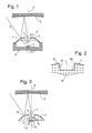
- Fig. 1 shows a schematic section through a camera with a mirror-lens lens.
- the camera comprises a cup-shaped housing 1 with a light-sensitive element arranged on the optical axis A, such as a CCD (Charge Coupled Device) 2.
- the housing is closed on its upper side by a carrier body 3 of a transparent material in optical quality.
- the support body 3 has an outer surface in the form of a convex hyperboloid of revolution symmetrical about the optical axis A, which is vapor-deposited with an aluminum or silver layer to form a first mirror 4.
- a second mirror 5 here in the form of a concave Rotationshyperboloids arranged.
- the lens By the back against the surface of the mirror 4 position of the lens 8, the lens is protected from grazing incident stray light. Such scattered light can only reach the side wall 9 of the recess 7. In order to avoid a reflection of the scattered light from there onto the lens 8, the side wall 9 can be blackened.
- the lens 8 may be provided with an antireflection coating. This may be mounted instead of a blackening on the side wall 9 to protect the lens 8 from stray light. It causes that incident on the side wall 9 scattered light virtually completely enters the carrier body 3 behind the first mirror 4 and is discharged by total reflection within the carrier body 3 to its outer edges.
- the secondary focus F2 'of the second mirror 5 lies beyond the mirror 4, i.e., the second mirror F2'. in the recess 7.
- this secondary focus F2 'on the CCD chip 2 with the aid of the lens 8 it must also be set back against the surface of the first mirror 4, at the bottom of the recess 7 still below the secondary focus F2 be arranged.
- the CCD chip 2 facing surface of the lens 8 is raised above adjacent areas of the back of the support body 3 and can therefore be polished without difficulty to improve the quality of the surface, if not already in the prototyping sufficient quality can be obtained.
- the surface of the lens 8 forming the bottom of the recess 7 is difficult to polish due to its position, at least in its edge regions.
- the aforementioned black layer is applied to the side wall 9 of the recess 7 not only for the purpose of suppressing stray light, but also in those edge areas of the lens 8 in which sufficient surface quality can not be achieved with sufficient certainty. This is illustrated by way of example in FIG. 2, which shows an enlarged section through the central region of the carrier body 3 and the lens 8, wherein the absorbing black layer is designated 10.
- FIG. 3 shows a further development of the camera from FIG. 1.
- the housing 1 and the CCD chip 2 are not shown again in FIG. 3, since they do not differ from those of FIG.
- the lens 8 which is formed integrally with the carrier body 3 is not raised above the rear side of the carrier body 3; rather, the rear side of the carrier body 3 also has a recess 11, the bottom of which is formed by the rear side of the lens 8 ,
- the two cylindrical, aligned recesses 7, 11 can be considered as two parts of an optical tube, which extends along the optical axis A and in which the lens 8 is held.
- the recess 11 serves here simultaneously as a plug-in socket into which an intermediate tube 12 is inserted, which in turn contains a number of further lenses 13.
- the integral with the carrier body 3 lens 8 and the lenses 13 of the intermediate tube 12 form a lens objective. Since the lens 8, which is the largest lens of this lens lens as a front lens, is not held in intermediate tube 12, the diameter of the intermediate tube 12 does not need to exceed that of the front lens, allowing a compact design of the entire objective.
- Fig. 4 shows a further embodiment of the mirror lens according to the invention, in which the lens 8 is not formed integrally with the carrier body 3 of the first mirror 4, but this carrier body 3 has a through bore 15 with an inner shoulder, which has a tube for holding the lens 8 represents.
- the tube 15 is widened on the side of the shoulder remote from the mirror 4, so that the lens 8 and a further lens 12 carrying intermediate tube 12 are inserted from the rear side of the carrier body 3 and fastened in the carrier body 3 can be.
- This construction makes it possible to manufacture, polish and coat the lens 8 separately from the carrier body 3 so that it can have an excellent optical quality over the entire surface, and then mount it in the tube 15 of the carrier body 3.
- the support body 3 is entirely made of a transparent material of optical quality; it may be like the second mirror 5 made of a transparent material, are placed on the optical properties no requirements.
Landscapes
- Physics & Mathematics (AREA)
- General Physics & Mathematics (AREA)
- Optics & Photonics (AREA)
- Lenses (AREA)
- Lens Barrels (AREA)
- Stereoscopic And Panoramic Photography (AREA)
Claims (8)
- Objectif photographique, comprenant un premier miroir (4) et au moins un deuxième miroir (5) et un système de lentilles avec une lentille frontale (8) et au moins une autre lentille,
dans lequel un tube (7 ; 7, 11 ; 15), dans lequel la lentille frontale (8) est ancrée, est réalisé par un corps de support (3) du premier miroir (4),
caractérisé en ce que les lentilles (13) du système de lentilles, à l'exception de la lentille frontale (8) de celles-ci, sont montées dans un tube intermédiaire (12) qui est inséré dans le tube (11 ; 15) du miroir (4). - Objectif photographique selon la revendication 1, caractérisé en ce que les miroirs (4, 5) et la lentille (8) présentent un axe optique A commun.
- Objectif photographique selon la revendication 1 ou 2, caractérisé en ce que la trajectoire des rayons dans l'objectif s'étend du premier miroir (4) à la lentille (8) en passant par le deuxième miroir (5).
- Objectif photographique selon l'une quelconque des revendications précédentes, caractérisé en ce que la lentille (8) est disposée en retrait derrière la surface du premier miroir (4).
- Objectif photographique selon l'une quelconque des revendications précédentes, caractérisé en ce qu'au moins le premier miroir (4) est un hyperboloïde.
- Objectif photographique selon l'une quelconque des revendications précédentes, caractérisé en ce que la lentille (8) est réalisée de façon intégrale avec le corps de support (3) du premier miroir (4).
- Objectif photographique selon l'une quelconque des revendications 1 à 5, caractérisé en ce que la lentille (8) est insérée dans le tube (15).
- Caméra panoramique, caractérisée par un objectif selon l'une quelconque des revendications précédentes.
Applications Claiming Priority (3)
| Application Number | Priority Date | Filing Date | Title |
|---|---|---|---|
| DE10256794A DE10256794A1 (de) | 2002-12-05 | 2002-12-05 | Panoramaobjektiv und -kamera |
| DE10256794 | 2002-12-05 | ||
| PCT/EP2003/013481 WO2004051340A1 (fr) | 2002-12-05 | 2003-12-01 | Objectif panoramique et camera panoramique |
Publications (2)
| Publication Number | Publication Date |
|---|---|
| EP1567904A1 EP1567904A1 (fr) | 2005-08-31 |
| EP1567904B1 true EP1567904B1 (fr) | 2006-06-07 |
Family
ID=32335987
Family Applications (1)
| Application Number | Title | Priority Date | Filing Date |
|---|---|---|---|
| EP03782256A Expired - Lifetime EP1567904B1 (fr) | 2002-12-05 | 2003-12-01 | Objectif panoramique et camera panoramique |
Country Status (6)
| Country | Link |
|---|---|
| US (1) | US20060098304A1 (fr) |
| EP (1) | EP1567904B1 (fr) |
| JP (1) | JP2006509228A (fr) |
| AU (1) | AU2003289917A1 (fr) |
| DE (2) | DE10256794A1 (fr) |
| WO (1) | WO2004051340A1 (fr) |
Families Citing this family (4)
| Publication number | Priority date | Publication date | Assignee | Title |
|---|---|---|---|---|
| RU2335003C2 (ru) * | 2006-09-21 | 2008-09-27 | ООО "Лаборатория трехмерного зрения" | Панорамная зеркально-линзовая система с видеокамерой |
| WO2010019757A1 (fr) * | 2008-08-14 | 2010-02-18 | Remotereality Corporation | Appareil photo panoramique à trois miroirs |
| US8305425B2 (en) | 2008-08-22 | 2012-11-06 | Promos Technologies, Inc. | Solid-state panoramic image capture apparatus |
| DE102018126143A1 (de) | 2018-10-22 | 2020-04-23 | Bayerische Motoren Werke Aktiengesellschaft | Außenkamera für ein Kraftfahrzeug |
Family Cites Families (9)
| Publication number | Priority date | Publication date | Assignee | Title |
|---|---|---|---|---|
| US4106856A (en) * | 1976-07-06 | 1978-08-15 | The Perkin-Elmer Corporation | Stray light control in an optical system |
| US4395093A (en) * | 1981-05-21 | 1983-07-26 | The United States Of America As Represented By The Secretary Of The Navy | Lens system for panoramic imagery |
| US4484801A (en) * | 1982-09-20 | 1984-11-27 | The United States Of America As Represented By The Secretary Of The Navy | Panoramic lens |
| GB2158261A (en) * | 1984-05-05 | 1985-11-06 | Pilkington Perkin Elmer Ltd | Optical apparatus for transmitting, and splitting infra-red and visible radiation |
| DE9400864U1 (de) * | 1994-01-19 | 1994-03-31 | Beck, Erich, Dr.med., 86356 Neusäß | Vergrößernde Sehbrille mit Spiegelsystem |
| US6449103B1 (en) * | 1997-04-16 | 2002-09-10 | Jeffrey R. Charles | Solid catadioptric omnidirectional optical system having central coverage means which is associated with a camera, projector, medical instrument, or similar article |
| US6356296B1 (en) * | 1997-05-08 | 2002-03-12 | Behere Corporation | Method and apparatus for implementing a panoptic camera system |
| US6597520B2 (en) * | 1999-01-13 | 2003-07-22 | Be Here Corporation | Panoramic imaging arrangement |
| AU4082801A (en) * | 2000-03-16 | 2001-09-24 | Lee Scott Friend | Imaging apparatus |
-
2002
- 2002-12-05 DE DE10256794A patent/DE10256794A1/de not_active Withdrawn
-
2003
- 2003-12-01 EP EP03782256A patent/EP1567904B1/fr not_active Expired - Lifetime
- 2003-12-01 AU AU2003289917A patent/AU2003289917A1/en not_active Abandoned
- 2003-12-01 DE DE50303745T patent/DE50303745D1/de not_active Expired - Fee Related
- 2003-12-01 US US10/535,303 patent/US20060098304A1/en not_active Abandoned
- 2003-12-01 JP JP2004556236A patent/JP2006509228A/ja not_active Abandoned
- 2003-12-01 WO PCT/EP2003/013481 patent/WO2004051340A1/fr not_active Ceased
Also Published As
| Publication number | Publication date |
|---|---|
| AU2003289917A1 (en) | 2004-06-23 |
| DE50303745D1 (de) | 2006-07-20 |
| JP2006509228A (ja) | 2006-03-16 |
| EP1567904A1 (fr) | 2005-08-31 |
| WO2004051340A1 (fr) | 2004-06-17 |
| DE10256794A1 (de) | 2004-06-24 |
| US20060098304A1 (en) | 2006-05-11 |
Similar Documents
| Publication | Publication Date | Title |
|---|---|---|
| DE60219839T2 (de) | Abbildungsvorrichtung und Verfahren zu deren Herstellung | |
| DE69727102T2 (de) | Integrierte hochauflösende Rundum-Sensoroptik | |
| DE69623182T2 (de) | Katadioptrische Einzellinse | |
| DE102010040030B4 (de) | Objektiv und Bildaufnahmesystem | |
| DE60224237T2 (de) | Abbildungsvorrichtung | |
| DE69601533T2 (de) | Rückblickvorrichtung für kraftfahrzeug | |
| DE69109664T2 (de) | Optische elemente mit gradientenindex und katadioptrische optische systeme. | |
| DE4108137A1 (de) | Optisches abbildungssystem | |
| DE1497574A1 (de) | Abbildendes optisches System | |
| DE102017211507A1 (de) | Anti-Reflexionsanordnung für eine Frontscheiben-Anzeigeeinrichtung sowie Frontscheiben-Anzeigeeinrichtung | |
| DE3214269A1 (de) | Gekuehlte feldoptik fuer infrarotteleskope | |
| DE60121561T2 (de) | Spiegelteleskop | |
| DE102006044355B4 (de) | Fotografisches Weitwinkel-Zoom-Objektiv vom Retrofokustyp | |
| DE60200370T2 (de) | Konzentrisches ultraweitwinkel scannersystem mit stückweise flacher detektoranordnung | |
| DE4104557A1 (de) | Reellbildsucher | |
| EP1567904B1 (fr) | Objectif panoramique et camera panoramique | |
| DE2627248A1 (de) | Lichtmesseinrichtung in einer einaeugigen spiegelreflexkamera | |
| DE102005021506A1 (de) | Optisches Einzelelement und seine Verwendung | |
| DE6940703U (de) | Spiegelreflexkamera. | |
| DE2938449A1 (de) | Albada-sucher | |
| DE19958332A1 (de) | Optisches System für einen Reellbildsucher | |
| DE4396177C2 (de) | Panoramaspiegelobjektiv | |
| DE102005018010B3 (de) | Winkelvorsatz für den Einblick einer Meßsucherkamera | |
| DD284568A7 (de) | Gegenlichtblende fuer hochqualitative sternsensoren | |
| AT166197B (fr) |
Legal Events
| Date | Code | Title | Description |
|---|---|---|---|
| PUAI | Public reference made under article 153(3) epc to a published international application that has entered the european phase |
Free format text: ORIGINAL CODE: 0009012 |
|
| 17P | Request for examination filed |
Effective date: 20050407 |
|
| AK | Designated contracting states |
Kind code of ref document: A1 Designated state(s): AT BE BG CH CY CZ DE DK EE ES FI FR GB GR HU IE IT LI LU MC NL PT RO SE SI SK TR |
|
| AX | Request for extension of the european patent |
Extension state: AL LT LV MK |
|
| GRAP | Despatch of communication of intention to grant a patent |
Free format text: ORIGINAL CODE: EPIDOSNIGR1 |
|
| RBV | Designated contracting states (corrected) |
Designated state(s): DE FR GB |
|
| DAX | Request for extension of the european patent (deleted) | ||
| GRAS | Grant fee paid |
Free format text: ORIGINAL CODE: EPIDOSNIGR3 |
|
| GRAA | (expected) grant |
Free format text: ORIGINAL CODE: 0009210 |
|
| AK | Designated contracting states |
Kind code of ref document: B1 Designated state(s): DE FR GB |
|
| PG25 | Lapsed in a contracting state [announced via postgrant information from national office to epo] |
Ref country code: GB Free format text: LAPSE BECAUSE OF FAILURE TO SUBMIT A TRANSLATION OF THE DESCRIPTION OR TO PAY THE FEE WITHIN THE PRESCRIBED TIME-LIMIT Effective date: 20060607 |
|
| REG | Reference to a national code |
Ref country code: GB Ref legal event code: FG4D Free format text: NOT ENGLISH |
|
| REF | Corresponds to: |
Ref document number: 50303745 Country of ref document: DE Date of ref document: 20060720 Kind code of ref document: P |
|
| ET | Fr: translation filed | ||
| GBV | Gb: ep patent (uk) treated as always having been void in accordance with gb section 77(7)/1977 [no translation filed] |
Effective date: 20060607 |
|
| PLBE | No opposition filed within time limit |
Free format text: ORIGINAL CODE: 0009261 |
|
| STAA | Information on the status of an ep patent application or granted ep patent |
Free format text: STATUS: NO OPPOSITION FILED WITHIN TIME LIMIT |
|
| RAP2 | Party data changed (patent owner data changed or rights of a patent transferred) |
Owner name: DAIMLERCHRYSLER AG |
|
| 26N | No opposition filed |
Effective date: 20070308 |
|
| PG25 | Lapsed in a contracting state [announced via postgrant information from national office to epo] |
Ref country code: DE Free format text: LAPSE BECAUSE OF NON-PAYMENT OF DUE FEES Effective date: 20070703 |
|
| REG | Reference to a national code |
Ref country code: FR Ref legal event code: ST Effective date: 20070831 |
|
| PG25 | Lapsed in a contracting state [announced via postgrant information from national office to epo] |
Ref country code: FR Free format text: LAPSE BECAUSE OF NON-PAYMENT OF DUE FEES Effective date: 20070102 |