EP1567904B1 - Panoramic objective and panoramic camera - Google Patents
Panoramic objective and panoramic camera Download PDFInfo
- Publication number
- EP1567904B1 EP1567904B1 EP03782256A EP03782256A EP1567904B1 EP 1567904 B1 EP1567904 B1 EP 1567904B1 EP 03782256 A EP03782256 A EP 03782256A EP 03782256 A EP03782256 A EP 03782256A EP 1567904 B1 EP1567904 B1 EP 1567904B1
- Authority
- EP
- European Patent Office
- Prior art keywords
- lens
- mirror
- carrier body
- panoramic
- objective
- Prior art date
- Legal status (The legal status is an assumption and is not a legal conclusion. Google has not performed a legal analysis and makes no representation as to the accuracy of the status listed.)
- Expired - Lifetime
Links
- 230000003287 optical effect Effects 0.000 claims description 12
- 238000003384 imaging method Methods 0.000 description 4
- 239000011248 coating agent Substances 0.000 description 3
- 238000000576 coating method Methods 0.000 description 3
- 239000012780 transparent material Substances 0.000 description 3
- BQCADISMDOOEFD-UHFFFAOYSA-N Silver Chemical compound [Ag] BQCADISMDOOEFD-UHFFFAOYSA-N 0.000 description 1
- XAGFODPZIPBFFR-UHFFFAOYSA-N aluminium Chemical compound [Al] XAGFODPZIPBFFR-UHFFFAOYSA-N 0.000 description 1
- 229910052782 aluminium Inorganic materials 0.000 description 1
- 238000010276 construction Methods 0.000 description 1
- 230000007547 defect Effects 0.000 description 1
- 230000000694 effects Effects 0.000 description 1
- 238000002347 injection Methods 0.000 description 1
- 239000007924 injection Substances 0.000 description 1
- 238000003780 insertion Methods 0.000 description 1
- 230000037431 insertion Effects 0.000 description 1
- 238000003754 machining Methods 0.000 description 1
- 238000004519 manufacturing process Methods 0.000 description 1
- 239000000463 material Substances 0.000 description 1
- 238000009304 pastoral farming Methods 0.000 description 1
- 238000005498 polishing Methods 0.000 description 1
- 238000001338 self-assembly Methods 0.000 description 1
- 229910052709 silver Inorganic materials 0.000 description 1
- 239000004332 silver Substances 0.000 description 1
Images

Classifications
-
- G—PHYSICS
- G02—OPTICS
- G02B—OPTICAL ELEMENTS, SYSTEMS OR APPARATUS
- G02B13/00—Optical objectives specially designed for the purposes specified below
- G02B13/06—Panoramic objectives; So-called "sky lenses" including panoramic objectives having reflecting surfaces
Definitions
- the present invention relates to a lens using both mirrors and lenses for imaging, and to a camera having such an objective.
- Imaging aplanar mirrors have long been used in extremely long focal length photographic lenses because they allow these lenses to be made significantly shorter than their focal length, significantly reducing the weight of such a lens compared to a corresponding lens in lens optics improves its handling.
- a lens in which two mirrors are formed at interfaces of a transparent body, wherein the central region of the first mirror remains without a reflective coating, so that rays can reach a lens system through this central region, and wherein the shape of the central region is different from that of the surrounding mirror surface to account for refractive effects of the transparent body.
- lenses are realized with mirror and lens optics by first the lens optics is provided as a finished assembly and attached to the mirror via a bracket. Often the lens optics is a functioning lens as such. Due to the size of this lens and the given by the size and focal length of the lens required distance to the mirrors of the miniaturization of a combined mirror-lens lens limits are set. In addition, due to the optical properties of the mirror, the lens-optical objective must be defocused in a defined manner so that the overall arrangement produces a sharp image. This represents an adjustment effort.
- US 2002/0154417 A1 discloses a photographic objective having a first and a second mirror in which a lens is anchored in a tube formed by the first mirror.
- the beam path of the light incident on the objective lens runs via this first mirror via the second mirror to the lens, which has a common optical axis with the mirrors.
- the object of the invention is to provide a photographic lens with mirrors and at least one lens that can be made simple and inexpensive and is well suited for miniaturization.
- the object is achieved by a lens with the features of claim 1.
- the simplification and miniaturization is achieved in that a carrier body, on which the first mirror is formed, is also used as a tube for holding the at least one lens.
- the lens is therefore not surrounded by its own, the space requirement of the lens-increasing tube as in conventional, forming a self-assembly lens optics.
- the tube which holds the lens but also the lens itself is integrally formed with the support material of the mirror. This allows a simple and inexpensive position of the carrier body of the mirror and the lens in one operation, for. B. by plastic injection.
- the lens is produced separately from the carrier body of the mirror and inserted into the tube formed in the carrier body. This facilitates fine machining of the refractive surfaces of the lens prior to insertion, e.g. B. by polishing, applying an anti-reflection coating, etc ..
- the lens mounted in the tube of the mirror in this manner may in particular be the front lens of a lens system.
- Other lenses of such a lens system which are generally smaller in diameter than the front lens, may be mounted in an intermediate tube which is inserted into the tube formed by the mirror.
- the lens is recessed behind the surface of the first mirror, i. there is a portion of the tube that extends between the surface of the first mirror and the lens, and that can act as a lens hood for the lens.
- a hyperboloid is preferably selected as the first mirror, this being designed in the form of a paraboloid, ellipsoid or in a general form of a conical section rotation.
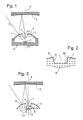
- Fig. 1 shows a schematic section through a camera with a mirror-lens lens.
- the camera comprises a cup-shaped housing 1 with a light-sensitive element arranged on the optical axis A, such as a CCD (Charge Coupled Device) 2.
- the housing is closed on its upper side by a carrier body 3 of a transparent material in optical quality.
- the support body 3 has an outer surface in the form of a convex hyperboloid of revolution symmetrical about the optical axis A, which is vapor-deposited with an aluminum or silver layer to form a first mirror 4.
- a second mirror 5 here in the form of a concave Rotationshyperboloids arranged.
- the lens By the back against the surface of the mirror 4 position of the lens 8, the lens is protected from grazing incident stray light. Such scattered light can only reach the side wall 9 of the recess 7. In order to avoid a reflection of the scattered light from there onto the lens 8, the side wall 9 can be blackened.
- the lens 8 may be provided with an antireflection coating. This may be mounted instead of a blackening on the side wall 9 to protect the lens 8 from stray light. It causes that incident on the side wall 9 scattered light virtually completely enters the carrier body 3 behind the first mirror 4 and is discharged by total reflection within the carrier body 3 to its outer edges.
- the secondary focus F2 'of the second mirror 5 lies beyond the mirror 4, i.e., the second mirror F2'. in the recess 7.
- this secondary focus F2 'on the CCD chip 2 with the aid of the lens 8 it must also be set back against the surface of the first mirror 4, at the bottom of the recess 7 still below the secondary focus F2 be arranged.
- the CCD chip 2 facing surface of the lens 8 is raised above adjacent areas of the back of the support body 3 and can therefore be polished without difficulty to improve the quality of the surface, if not already in the prototyping sufficient quality can be obtained.
- the surface of the lens 8 forming the bottom of the recess 7 is difficult to polish due to its position, at least in its edge regions.
- the aforementioned black layer is applied to the side wall 9 of the recess 7 not only for the purpose of suppressing stray light, but also in those edge areas of the lens 8 in which sufficient surface quality can not be achieved with sufficient certainty. This is illustrated by way of example in FIG. 2, which shows an enlarged section through the central region of the carrier body 3 and the lens 8, wherein the absorbing black layer is designated 10.
- FIG. 3 shows a further development of the camera from FIG. 1.
- the housing 1 and the CCD chip 2 are not shown again in FIG. 3, since they do not differ from those of FIG.
- the lens 8 which is formed integrally with the carrier body 3 is not raised above the rear side of the carrier body 3; rather, the rear side of the carrier body 3 also has a recess 11, the bottom of which is formed by the rear side of the lens 8 ,
- the two cylindrical, aligned recesses 7, 11 can be considered as two parts of an optical tube, which extends along the optical axis A and in which the lens 8 is held.
- the recess 11 serves here simultaneously as a plug-in socket into which an intermediate tube 12 is inserted, which in turn contains a number of further lenses 13.
- the integral with the carrier body 3 lens 8 and the lenses 13 of the intermediate tube 12 form a lens objective. Since the lens 8, which is the largest lens of this lens lens as a front lens, is not held in intermediate tube 12, the diameter of the intermediate tube 12 does not need to exceed that of the front lens, allowing a compact design of the entire objective.
- Fig. 4 shows a further embodiment of the mirror lens according to the invention, in which the lens 8 is not formed integrally with the carrier body 3 of the first mirror 4, but this carrier body 3 has a through bore 15 with an inner shoulder, which has a tube for holding the lens 8 represents.
- the tube 15 is widened on the side of the shoulder remote from the mirror 4, so that the lens 8 and a further lens 12 carrying intermediate tube 12 are inserted from the rear side of the carrier body 3 and fastened in the carrier body 3 can be.
- This construction makes it possible to manufacture, polish and coat the lens 8 separately from the carrier body 3 so that it can have an excellent optical quality over the entire surface, and then mount it in the tube 15 of the carrier body 3.
- the support body 3 is entirely made of a transparent material of optical quality; it may be like the second mirror 5 made of a transparent material, are placed on the optical properties no requirements.
Landscapes
- Physics & Mathematics (AREA)
- General Physics & Mathematics (AREA)
- Optics & Photonics (AREA)
- Lenses (AREA)
- Lens Barrels (AREA)
- Stereoscopic And Panoramic Photography (AREA)
Description
Die vorliegende Erfindung betrifft ein Objektiv, das zur Bilderzeugung sowohl Spiegel als auch Linsen verwendet, und eine Kamera, die ein solches Objektiv aufweist.The present invention relates to a lens using both mirrors and lenses for imaging, and to a camera having such an objective.
Bildgebende, aplanare Spiegel werden seit langem in photographischen Objektiven für extrem lange Brennweiten eingesetzt, da sie es ermöglichen, diese Objektive erheblich kürzer zu bauen, als ihrer Brennweite entspricht, was das Gewicht eines solchen Objektivs im Vergleich zu einem entsprechenden Objektiv in Linsenoptik erheblich verringert und seine Handhabbarkeit verbessert.Imaging aplanar mirrors have long been used in extremely long focal length photographic lenses because they allow these lenses to be made significantly shorter than their focal length, significantly reducing the weight of such a lens compared to a corresponding lens in lens optics improves its handling.
In den letzten Jahren sind auch zahlreiche Konstruktionen von Objektiven mit extrem großen Blickwinkeln bis hin zu 360°-Rundumblick vorgeschlagen worden, die aplanare Spiegeloberflächen als bildgebende Elemente verwenden. Einen Überblick über die Bauformen derartiger Objektive und die Arten der darin verwendeten Spiegelflächen gibt der Artikel "Folded Catadioptric Cameras" von S.K. Nayar und V. Peri, in Proceedings of Conference on Computer Vision and Recognition (CVPR), Vol. 2, IEEE, pages 217 ff.In recent years, numerous designs have also been proposed for lenses with extremely large viewing angles up to a 360 ° overall view, which use aplanar mirror surfaces as imaging elements. An overview of the types of such lenses and the types of mirror surfaces used therein is given in the article "Folded Catadioptric Cameras" by S.K. Nayar and V. Peri, in Proceedings of Conference on Computer Vision and Recognition (CVPR), Vol. 2, IEEE, pages 217 ff.
Aus WO 00/41024 ist ein Objektiv bekannt, bei dem zwei Spiegel an Grenzflächen eines transparenten Körpers ausgebildet sind, wobei der mittlere Bereich des ersten Spiegels ohne reflektierende Beschichtung bleibt, so dass Strahlen durch diesen mittleren Bereich ein Linsensystem erreichen können, und wobei die Form des mittleren Bereichs eine andere ist als die der umgebenden Spiegelfläche, um Brechungseffekten des transparenten Körpers Rechnung zu tragen.From WO 00/41024 a lens is known, in which two mirrors are formed at interfaces of a transparent body, wherein the central region of the first mirror remains without a reflective coating, so that rays can reach a lens system through this central region, and wherein the shape of the central region is different from that of the surrounding mirror surface to account for refractive effects of the transparent body.
Üblicherweise werden Objektive mit Spiegel- und Linsenoptik realisiert, indem zunächst die Linsenoptik als eine fertige Baugruppe bereitgestellt wird und an dieser über eine Halterung die Spiegel befestigt werden. Häufig handelt es sich bei der Linsenoptik um ein als solches funktionsfähiges Objektiv. Durch die Größe dieses Objektivs und den durch die Größe und Brennbreite des Objektivs vorgegebenen nötigen Abstand zu den Spiegeln sind der Miniaturisierung eines kombinierten Spiegel-Linsen-Objektivs Grenzen gesetzt. Außerdem muss aufgrund der optischen Eigenschaften der Spiegel das linsenoptische Objektiv in definierter Weise defokussiert werden, damit die Gesamtanordnung ein scharfes Bild erzeugt. Dies stellt einen Justierungsaufwand dar.Typically, lenses are realized with mirror and lens optics by first the lens optics is provided as a finished assembly and attached to the mirror via a bracket. Often the lens optics is a functioning lens as such. Due to the size of this lens and the given by the size and focal length of the lens required distance to the mirrors of the miniaturization of a combined mirror-lens lens limits are set. In addition, due to the optical properties of the mirror, the lens-optical objective must be defocused in a defined manner so that the overall arrangement produces a sharp image. This represents an adjustment effort.
In der Offenlegungsschrift US 2002/0154417 A1 wird ein photographisches Objektiv mit einem ersten und einem zweiten Spiegel beschrieben, bei welchem eine Linse in einem Tubus verankert ist, der durch den ersten Spiegel gebildet wird. Der Strahlengang des auf das Objektiv einfallenden Lichts verläuft über diesen ersten Spiegel über den zweiten Spiegel zu der Linse, welche mit den Spiegeln eine gemeinsame optische Achse aufweist.US 2002/0154417 A1 discloses a photographic objective having a first and a second mirror in which a lens is anchored in a tube formed by the first mirror. The beam path of the light incident on the objective lens runs via this first mirror via the second mirror to the lens, which has a common optical axis with the mirrors.
Aufgabe der Erfindung ist, ein fotographisches Objektiv mit Spiegeln und wenigstens einer Linse anzugeben, das einfach und preiswert gefertigt werden kann und gut für eine Miniaturisierung geeignet ist.The object of the invention is to provide a photographic lens with mirrors and at least one lens that can be made simple and inexpensive and is well suited for miniaturization.
Die Aufgabe wird gelöst durch ein Objektiv mit den Merkmalen des Anspruchs 1. Die Vereinfachung und Miniaturisierbarkeit wird dadurch erreicht, dass ein Trägerkörper, auf welchem der erste Spiegel gebildet ist, gleichzeitig als Tubus für die Halterung der wenigstens einen Linse genutzt wird. Die Linse ist daher nicht wie bei herkömmlichen, eine selbständige Baueinheit bildenden Linsenoptiken von einem eigenen, den Platzbedarf des Objektivs erhöhenden Tubus umgeben.The object is achieved by a lens with the features of
Einer ersten bevorzugten Ausgestaltung der Erfindung zufolge ist nicht nur der Tubus, der die Linse hält, sondern auch die Linse selbst einteilig mit dem Trägermaterial des Spiegels ausgebildet. Dies erlaubt eine einfache und preiswerte Her- stellung des Trägerkörpers des Spiegels und der Linse in einem Arbeitsgang, z. B. durch Kunststoff-Spritzguss.According to a first preferred embodiment of the invention, not only the tube which holds the lens, but also the lens itself is integrally formed with the support material of the mirror. This allows a simple and inexpensive position of the carrier body of the mirror and the lens in one operation, for. B. by plastic injection.
Einer zweiten bevorzugten Ausgestaltung zufolge ist die Linse getrennt vom Trägerkörper des Spiegels hergestellt und in den im Trägerkörper gebildeten Tubus eingeschoben. Dies erleichtert eine Feinbearbeitung der lichtbrechenden Oberflächen der Linse vor dem Einschieben, z. B. durch Polieren, Aufbringen einer Antireflexbeschichtung, etc..According to a second preferred embodiment, the lens is produced separately from the carrier body of the mirror and inserted into the tube formed in the carrier body. This facilitates fine machining of the refractive surfaces of the lens prior to insertion, e.g. B. by polishing, applying an anti-reflection coating, etc ..
Bei der in dieser Weise im Tubus des Spiegels angebrachten Linse kann es sich insbesondere um die Frontlinse eines Linsensystems handeln. Weitere Linsen eines solchen Linsensystems, die im Allgemeinen einen kleineren Durchmesser als die Frontlinse haben, können in einem Zwischentubus montiert sein, der in den vom Spiegel gebildeten Tubus eingeschoben ist.The lens mounted in the tube of the mirror in this manner may in particular be the front lens of a lens system. Other lenses of such a lens system, which are generally smaller in diameter than the front lens, may be mounted in an intermediate tube which is inserted into the tube formed by the mirror.
Vorzugsweise ist die Linse hinter die Oberfläche des ersten Spiegels zurückspringend angeordnet, d.h. es gibt einen Abschnitt des Tubus, der sich zwischen der Oberfläche des ersten Spiegels und der Linse erstreckt, und der als eine Streulichtblende für die Linse wirken kann.Preferably, the lens is recessed behind the surface of the first mirror, i. there is a portion of the tube that extends between the surface of the first mirror and the lens, and that can act as a lens hood for the lens.
Um eine solche zurückspringende Montage der Linse zu ermöglichen, wird als erster Spiegel vorzugsweise ein Hyperboloid gewählt, wobei dieser in Form eines Paraboloiden, Elipsoiden oder in einer allgemeinen Form einer Kegelschnittrotation ausgeführt ist.In order to allow such a recessed mounting of the lens, a hyperboloid is preferably selected as the first mirror, this being designed in the form of a paraboloid, ellipsoid or in a general form of a conical section rotation.
Weitere Merkmale und Vorteile der Erfindung ergeben sich aus den nachfolgenden Beschreibungen von Ausführungsbeispielen mit Bezug auf die beigefügten Figuren.Further features and advantages of the invention will become apparent from the following descriptions of embodiments with reference to the accompanying figures.
Dabei zeigen:
- Fig. 1
- einen schematischen Schnitt durch ein von der vorliegenden Erfindung abweichendes Spiegel-Linsen-Objektiv
- Fig. 2
- ein vergrößertes Detail einer Variante dieses objectivs; und
- Fig. 3, 4
- Schnitte durch Spiegel-Linsen-Objektive gemäß Ausgestaltungen der Erfindung
- Fig. 1
- a schematic section through a deviating from the present invention mirror lens objective
- Fig. 2
- an enlarged detail of a variant of this objectivs; and
- Fig. 3, 4
- Sections through mirror lens objectives according to embodiments of the invention
Fig. 1 zeigt einen schematischen Schnitt durch eine Kamera mit einem Spiegel-Linsen-Objektiv. Die Kamera umfasst ein becherartiges Gehäuse 1 mit einem auf der optischen Achse A angeordneten lichtempfindlichen Element wie etwa einem CCD (Charge Coupled Device) 2. Das Gehäuse ist an seiner Oberseite durch einen Trägerkörper 3 aus einem transparenten Material in optischer Qualität verschlossen. Der Trägerkörper 3 hat eine Außenfläche in Form eines um die optische Achse A symmetrischen konvexen Rotationshyperboloids, die mit einer Aluminium- oder Silberschicht bedampft ist, um einen ersten Spiegel 4 zu bilden. In einem Abstand oberhalb des ersten Spiegels 4 ist ein zweiter Spiegel 5, hier in Form eines konkaven Rotationshyperboloids, angeordnet. Lichtstrahlen 6, die unter beliebigen Azimutwinkeln und aus einen großen Bereich von Zenitalwinkeln θ auf den ersten Spiegel 1 fallen, werden von diesem auf den zweiten Spiegel 5 und von dort in eine zentrale Aussparung 7 des Trägerkörpers 3 reflektiert, in der einteilig mit dem Trägerkörper 3 eine Linse 8 angeordnet ist, die ein Bild der Umgebung auf den CCD 2 projiziert.Fig. 1 shows a schematic section through a camera with a mirror-lens lens. The camera comprises a cup-
Durch die gegen die Oberfläche des Spiegels 4 zurück versetzte Lage der Linse 8 ist die Linse vor streifend einfallenden Streulicht geschützt. Derartiges Streulicht kann lediglich die Seitenwand 9 der Aussparung 7 erreichen. Um eine Reflexion des Streulichts von dort auf die Linse 8 zu vermeiden, kann die Seitenwand 9 geschwärzt sein.By the back against the surface of the
Zur Verbesserung der optischen Eigenschaften kann die Linse 8 mit einer Antireflexbeschichtung versehen sein. Diese kann anstelle einer Schwärzung auch an der Seitenwand 9 angebracht sein, um die Linse 8 vor Streulicht zu schützen. Sie bewirkt, dass auf die Seitenwand 9 treffendes Streulicht praktisch vollständig in den Trägerkörper 3 hinter dem ersten Spiegel 4 eintritt und durch Totalreflexion innerhalb des Trägerkörpers 3 zu dessen äußeren Rändern hin abgeführt wird.To improve the optical properties, the
Da bei dem Beispiel der Fig. 1 beide Spiegel 4, 5 Hyperboloide sind, liegt der sekundäre Fokus F2' des zweiten Spiegels 5 jenseits des Spiegels 4, d.h. in der Aussparung 7. Um diesen sekundären Fokus F2' mit Hilfe der Linse 8 auf den CCD-Chip 2 abbilden zu können, muss also auch diese gegen die Oberfläche des ersten Spiegels 4 rückversetzt, am Boden der Aussparung 7 noch unterhalb des sekundären Fokus F2' angeordnet sein.In the example of FIG. 1, since both
Wie Fig. 1 zeigt, ist die dem CCD-Chip 2 zugewandte Oberfläche der Linse 8 über angrenzende Bereiche der Rückseite des Trägerkörpers 3 erhaben und kann daher ohne Schwierigkeiten poliert werden, um die Qualität der Oberfläche zu verbessern, wenn die nicht bereits beim Urformen mit ausreichender Qualität erhalten werden kann. Die den Boden der Aussparung 7 bildende Oberfläche der Linse 8 ist aufgrund ihrer Lage jedoch zumindest in ihren Randbereichen schwierig zu polieren. Um zu verhindern, dass Fehler der Linse 8 in diesen Randbereichen die Abbildungseigenschaften beeinträchtigen, kann vorgesehen werden, das die bereits erwähnte schwarze Schicht nicht nur zur Unterdrückung von Streulicht an der Seitenwand 9 der Aussparung 7 angebracht wird, sondern auch in denjenigen Randbereichen der Linse 8, in denen eine ausreichende Oberflächenqualität nicht mit hinreichender Sicherheit erreicht werden kann. Dies ist exemplarisch in Fig. 2 dargestellt, die einen vergrößerten Schnitt durch den zentralen Bereich des Trägerkörpers 3 und die Linse 8 zeigt, wobei die absorbierende schwarze Schicht mit 10 bezeichnet ist.As shown in Fig. 1, the
Fig. 3 zeigt eine Weiterentwicklung der Kamera aus Fig. 1. Das Gehäuse 1 und der CCD-Chip 2 sind in Fig. 3 nicht erneut dargestellt, da sie sich von denen aus Fig. 1 nicht unterscheiden.FIG. 3 shows a further development of the camera from FIG. 1. The
Die mit dem Trägerkörper 3 einteilig ausgebildete Linse 8 ist bei der Ausgestaltung der Fig. 3 nicht über die Rückseite des Trägerkörpers 3 erhaben, vielmehr weist auch die Rückseite des Trägerkörpers 3 hier eine Aussparung 11 auf, dessen Boden durch die Rückseite der Linse 8 gebildet ist. Die zwei zylindrischen, miteinander fluchtenden Aussparungen 7, 11 können als zwei Teile eines optischen Tubus aufgefasst werden, der sich entlang der optischen Achse A erstreckt und in welchem die Linse 8 gehalten ist. Die Aussparung 11 dient hier gleichzeitig als eine Einsteckfassung, in welche ein Zwischentubus 12 eingeschoben ist, der seinerseits eine Anzahl von weiteren Linsen 13 enthält. Die mit dem Trägerkörper 3 einteilige Linse 8 und die Linsen 13 des Zwischentubus 12 bilden ein Linsenobjektiv. Da die Linse 8, die als Frontlinse die größte Linse dieses Linsenobjektivs ist, nicht in Zwischentubus 12 gehalten ist, braucht der Durchmesser des Zwischentubus 12 den der Frontlinse nicht zu überschreiten, was eine kompakte Bauform des gesamten Objektivs ermöglicht.In the embodiment of FIG. 3, the
Fig. 4 zeigt eine weitere Ausgestaltung des erfindungsgemäßen Spiegel-Linsenobjektivs, bei der die Linse 8 nicht einteilig mit dem Trägerkörper 3 des ersten Spiegels 4 ausgebildet ist, sondern dieser Trägerkörper 3 eine durchgehende Bohrung 15 mit einer inneren Schulter aufweist, die einen Tubus zur Halterung der Linse 8 darstellt. Bei der Ausgestaltung der Fig. 4 ist der Tubus 15 an der vom Spiegel 4 abgewandten Seite der Schulter verbreitert, so dass die Linse 8 und ein weitere Linsen 13 tragender Zwischentubus 12 von der Rückseite des Trägerkörpers 3 her eingeschoben und im Trägerkörper 3 befestigt werden können. Diese Konstruktion erlaubt es, die Linse 8 getrennt vom Trägerkörper 3 zu fertigen, zu polieren und zu beschichten, so dass sie auf der gesamten Oberfläche eine ausgezeichnete optische Qualität aufweisen kann, und sie erst anschließend in dem Tubus 15 des Trägerkörpers 3 zu montieren. Infolge dessen ist es auch nicht erforderlich, dass der Trägerkörper 3 zur Gänze aus einem transparenten Material von optischer Qualität gefertigt ist; er kann wie der des zweiten Spiegels 5 aus einem transparenten Material bestehen, an dessen optischen Eigenschaften keine Anforderungen gestellt werden. Fig. 4 shows a further embodiment of the mirror lens according to the invention, in which the
Claims (8)
- Photographic objective comprising a first (4) and at least one second mirror (5) and a lens system with a front lens (8) and at least one further lens, wherein a barrel (7; 7, 11; 15), in which the front lens (8) is anchored, is formed by a supporting body (3) of the first mirror (4), characterized in that, with the exception of its front lens (8), the lenses (13) of the lens system are mounted in an intermediate barrel (12) which is inserted into the barrel (11; 15) of the mirror (4).
- Photographic objective according to Claim 1, characterized in that the mirrors (4, 5) and the lens (8) have a common optical axis A.
- Photographic objective according to Claim 1 or 2, characterized in that the beam path in the objective extends from the first mirror (4) via the second mirror (5) to the lens (8).
- Photographic objective according to one of the preceding claims, characterized in that the lens (8) is recessed behind the surface of the first mirror (4).
- Photographic objective according to one of the preceding claims, characterized in that at least the first mirror (4) is a hyperboloid.
- Photographic objective according to one of the preceding claims, characterized in that the lens (8) is constructed of one piece with the supporting body (3) of the first mirror (4).
- Photographic objective according to one of Claims 1 to 5, characterized in that the lens (8) is inserted into the barrel (15).
- Panoramic camera, characterized by an objective according to one of the preceding claims.
Applications Claiming Priority (3)
| Application Number | Priority Date | Filing Date | Title |
|---|---|---|---|
| DE10256794 | 2002-12-05 | ||
| DE10256794A DE10256794A1 (en) | 2002-12-05 | 2002-12-05 | Panorama lens and camera |
| PCT/EP2003/013481 WO2004051340A1 (en) | 2002-12-05 | 2003-12-01 | Panoramic objective and panoramic camera |
Publications (2)
| Publication Number | Publication Date |
|---|---|
| EP1567904A1 EP1567904A1 (en) | 2005-08-31 |
| EP1567904B1 true EP1567904B1 (en) | 2006-06-07 |
Family
ID=32335987
Family Applications (1)
| Application Number | Title | Priority Date | Filing Date |
|---|---|---|---|
| EP03782256A Expired - Lifetime EP1567904B1 (en) | 2002-12-05 | 2003-12-01 | Panoramic objective and panoramic camera |
Country Status (6)
| Country | Link |
|---|---|
| US (1) | US20060098304A1 (en) |
| EP (1) | EP1567904B1 (en) |
| JP (1) | JP2006509228A (en) |
| AU (1) | AU2003289917A1 (en) |
| DE (2) | DE10256794A1 (en) |
| WO (1) | WO2004051340A1 (en) |
Families Citing this family (4)
| Publication number | Priority date | Publication date | Assignee | Title |
|---|---|---|---|---|
| RU2335003C2 (en) * | 2006-09-21 | 2008-09-27 | ООО "Лаборатория трехмерного зрения" | Panorama mirror-lens system with video camera |
| US8451318B2 (en) * | 2008-08-14 | 2013-05-28 | Remotereality Corporation | Three-mirror panoramic camera |
| US8305425B2 (en) | 2008-08-22 | 2012-11-06 | Promos Technologies, Inc. | Solid-state panoramic image capture apparatus |
| DE102018126143A1 (en) | 2018-10-22 | 2020-04-23 | Bayerische Motoren Werke Aktiengesellschaft | Outdoor camera for a motor vehicle |
Family Cites Families (9)
| Publication number | Priority date | Publication date | Assignee | Title |
|---|---|---|---|---|
| US4106856A (en) * | 1976-07-06 | 1978-08-15 | The Perkin-Elmer Corporation | Stray light control in an optical system |
| US4395093A (en) * | 1981-05-21 | 1983-07-26 | The United States Of America As Represented By The Secretary Of The Navy | Lens system for panoramic imagery |
| US4484801A (en) * | 1982-09-20 | 1984-11-27 | The United States Of America As Represented By The Secretary Of The Navy | Panoramic lens |
| GB2158261A (en) * | 1984-05-05 | 1985-11-06 | Pilkington Perkin Elmer Ltd | Optical apparatus for transmitting, and splitting infra-red and visible radiation |
| DE9400864U1 (en) * | 1994-01-19 | 1994-03-31 | Beck, Erich, Dr.med., 86356 Neusäß | Magnifying eye glasses with mirror system |
| US6449103B1 (en) * | 1997-04-16 | 2002-09-10 | Jeffrey R. Charles | Solid catadioptric omnidirectional optical system having central coverage means which is associated with a camera, projector, medical instrument, or similar article |
| US6356296B1 (en) * | 1997-05-08 | 2002-03-12 | Behere Corporation | Method and apparatus for implementing a panoptic camera system |
| US6597520B2 (en) * | 1999-01-13 | 2003-07-22 | Be Here Corporation | Panoramic imaging arrangement |
| WO2001068540A2 (en) * | 2000-03-16 | 2001-09-20 | Lee Scott Friend | Imaging apparatus |
-
2002
- 2002-12-05 DE DE10256794A patent/DE10256794A1/en not_active Withdrawn
-
2003
- 2003-12-01 JP JP2004556236A patent/JP2006509228A/en not_active Abandoned
- 2003-12-01 AU AU2003289917A patent/AU2003289917A1/en not_active Abandoned
- 2003-12-01 WO PCT/EP2003/013481 patent/WO2004051340A1/en not_active Ceased
- 2003-12-01 EP EP03782256A patent/EP1567904B1/en not_active Expired - Lifetime
- 2003-12-01 US US10/535,303 patent/US20060098304A1/en not_active Abandoned
- 2003-12-01 DE DE50303745T patent/DE50303745D1/en not_active Expired - Fee Related
Also Published As
| Publication number | Publication date |
|---|---|
| WO2004051340A1 (en) | 2004-06-17 |
| DE10256794A1 (en) | 2004-06-24 |
| JP2006509228A (en) | 2006-03-16 |
| EP1567904A1 (en) | 2005-08-31 |
| AU2003289917A1 (en) | 2004-06-23 |
| US20060098304A1 (en) | 2006-05-11 |
| DE50303745D1 (en) | 2006-07-20 |
Similar Documents
| Publication | Publication Date | Title |
|---|---|---|
| DE60219839T2 (en) | Imaging apparatus and method of making the same | |
| DE69727102T2 (en) | Integrated high-resolution all-round sensor optics | |
| DE69623182T2 (en) | Single catadioptric lens | |
| DE102010040030B4 (en) | Lens and imaging system | |
| DE60224237T2 (en) | imaging device | |
| DE69109664T2 (en) | OPTICAL ELEMENTS WITH GRADIENT INDEX AND CATADIOPTRIC OPTICAL SYSTEMS. | |
| DE4108137A1 (en) | OPTICAL IMAGING SYSTEM | |
| DE1497574A1 (en) | Imaging optical system | |
| DE102017211507A1 (en) | Anti-reflection arrangement for a windshield display device and windshield display device | |
| DE3214269A1 (en) | COOLED FIELD OPTICS FOR INFRARED TELESCOPES | |
| DE2317168A1 (en) | ATTACHMENT FOR THE RECORDING LENS OF A CAMERA | |
| DE60121561T2 (en) | MIRROR TELESCOPE | |
| DE102006044355B4 (en) | Wide angle wide angle zoom lens of retrofocus type | |
| DE60200370T2 (en) | CONCENTRIC ULTRA-WIDE ANGLE SCANNER SYSTEM WITH PARTIAL FLAT DETECTOR ASSEMBLY | |
| DE4104557A1 (en) | REEL IMAGE SEARCHER | |
| EP1567904B1 (en) | Panoramic objective and panoramic camera | |
| DE2627248A1 (en) | LIGHT MEASURING DEVICE IN A SINGLE-EYE MIRROR REFLEX CAMERA | |
| DE2643568A1 (en) | SMALL, SINGLE-EYED MIRROR REFLEX CAMERA | |
| DE6940703U (en) | MIRROR REFLEX CAMERA. | |
| DE2938449A1 (en) | Albada viewfinder for camera - has clear frame and reflecting frame on inside of lens to intensity image | |
| DE19958332A1 (en) | Optical system has lens system and ocular lens, two prisms and prism surfaces | |
| DE4396177C2 (en) | Reflection type field angle conversion optical device | |
| DE102005018010B3 (en) | Angular ancillary lens for attachment to the viewer of a measurement search camera has an image deflection element in the form of a fine prism | |
| DD284568A7 (en) | BACKLIGHTS FOR HIGH QUALITY STAR SENSORS | |
| AT166197B (en) |
Legal Events
| Date | Code | Title | Description |
|---|---|---|---|
| PUAI | Public reference made under article 153(3) epc to a published international application that has entered the european phase |
Free format text: ORIGINAL CODE: 0009012 |
|
| 17P | Request for examination filed |
Effective date: 20050407 |
|
| AK | Designated contracting states |
Kind code of ref document: A1 Designated state(s): AT BE BG CH CY CZ DE DK EE ES FI FR GB GR HU IE IT LI LU MC NL PT RO SE SI SK TR |
|
| AX | Request for extension of the european patent |
Extension state: AL LT LV MK |
|
| GRAP | Despatch of communication of intention to grant a patent |
Free format text: ORIGINAL CODE: EPIDOSNIGR1 |
|
| RBV | Designated contracting states (corrected) |
Designated state(s): DE FR GB |
|
| DAX | Request for extension of the european patent (deleted) | ||
| GRAS | Grant fee paid |
Free format text: ORIGINAL CODE: EPIDOSNIGR3 |
|
| GRAA | (expected) grant |
Free format text: ORIGINAL CODE: 0009210 |
|
| AK | Designated contracting states |
Kind code of ref document: B1 Designated state(s): DE FR GB |
|
| PG25 | Lapsed in a contracting state [announced via postgrant information from national office to epo] |
Ref country code: GB Free format text: LAPSE BECAUSE OF FAILURE TO SUBMIT A TRANSLATION OF THE DESCRIPTION OR TO PAY THE FEE WITHIN THE PRESCRIBED TIME-LIMIT Effective date: 20060607 |
|
| REG | Reference to a national code |
Ref country code: GB Ref legal event code: FG4D Free format text: NOT ENGLISH |
|
| REF | Corresponds to: |
Ref document number: 50303745 Country of ref document: DE Date of ref document: 20060720 Kind code of ref document: P |
|
| ET | Fr: translation filed | ||
| GBV | Gb: ep patent (uk) treated as always having been void in accordance with gb section 77(7)/1977 [no translation filed] |
Effective date: 20060607 |
|
| PLBE | No opposition filed within time limit |
Free format text: ORIGINAL CODE: 0009261 |
|
| STAA | Information on the status of an ep patent application or granted ep patent |
Free format text: STATUS: NO OPPOSITION FILED WITHIN TIME LIMIT |
|
| RAP2 | Party data changed (patent owner data changed or rights of a patent transferred) |
Owner name: DAIMLERCHRYSLER AG |
|
| 26N | No opposition filed |
Effective date: 20070308 |
|
| PG25 | Lapsed in a contracting state [announced via postgrant information from national office to epo] |
Ref country code: DE Free format text: LAPSE BECAUSE OF NON-PAYMENT OF DUE FEES Effective date: 20070703 |
|
| REG | Reference to a national code |
Ref country code: FR Ref legal event code: ST Effective date: 20070831 |
|
| PG25 | Lapsed in a contracting state [announced via postgrant information from national office to epo] |
Ref country code: FR Free format text: LAPSE BECAUSE OF NON-PAYMENT OF DUE FEES Effective date: 20070102 |