EP1567756B1 - Procede pour reguler l'injection de liquide dans un canal d'amenee d'un moteur ou d'une machine de travail - Google Patents
Procede pour reguler l'injection de liquide dans un canal d'amenee d'un moteur ou d'une machine de travail Download PDFInfo
- Publication number
- EP1567756B1 EP1567756B1 EP03812183A EP03812183A EP1567756B1 EP 1567756 B1 EP1567756 B1 EP 1567756B1 EP 03812183 A EP03812183 A EP 03812183A EP 03812183 A EP03812183 A EP 03812183A EP 1567756 B1 EP1567756 B1 EP 1567756B1
- Authority
- EP
- European Patent Office
- Prior art keywords
- nozzles
- group
- liquid
- mass flow
- nozzle
- Prior art date
- Legal status (The legal status is an assumption and is not a legal conclusion. Google has not performed a legal analysis and makes no representation as to the accuracy of the status listed.)
- Revoked
Links
Images

Classifications
-
- F—MECHANICAL ENGINEERING; LIGHTING; HEATING; WEAPONS; BLASTING
- F02—COMBUSTION ENGINES; HOT-GAS OR COMBUSTION-PRODUCT ENGINE PLANTS
- F02C—GAS-TURBINE PLANTS; AIR INTAKES FOR JET-PROPULSION PLANTS; CONTROLLING FUEL SUPPLY IN AIR-BREATHING JET-PROPULSION PLANTS
- F02C7/00—Features, components parts, details or accessories, not provided for in, or of interest apart form groups F02C1/00 - F02C6/00; Air intakes for jet-propulsion plants
- F02C7/12—Cooling of plants
- F02C7/14—Cooling of plants of fluids in the plant, e.g. lubricant or fuel
- F02C7/141—Cooling of plants of fluids in the plant, e.g. lubricant or fuel of working fluid
- F02C7/143—Cooling of plants of fluids in the plant, e.g. lubricant or fuel of working fluid before or between the compressor stages
- F02C7/1435—Cooling of plants of fluids in the plant, e.g. lubricant or fuel of working fluid before or between the compressor stages by water injection
-
- F—MECHANICAL ENGINEERING; LIGHTING; HEATING; WEAPONS; BLASTING
- F05—INDEXING SCHEMES RELATING TO ENGINES OR PUMPS IN VARIOUS SUBCLASSES OF CLASSES F01-F04
- F05D—INDEXING SCHEME FOR ASPECTS RELATING TO NON-POSITIVE-DISPLACEMENT MACHINES OR ENGINES, GAS-TURBINES OR JET-PROPULSION PLANTS
- F05D2250/00—Geometry
- F05D2250/50—Inlet or outlet
- F05D2250/51—Inlet
-
- F—MECHANICAL ENGINEERING; LIGHTING; HEATING; WEAPONS; BLASTING
- F05—INDEXING SCHEMES RELATING TO ENGINES OR PUMPS IN VARIOUS SUBCLASSES OF CLASSES F01-F04
- F05D—INDEXING SCHEME FOR ASPECTS RELATING TO NON-POSITIVE-DISPLACEMENT MACHINES OR ENGINES, GAS-TURBINES OR JET-PROPULSION PLANTS
- F05D2260/00—Function
- F05D2260/20—Heat transfer, e.g. cooling
- F05D2260/212—Heat transfer, e.g. cooling by water injection
-
- Y—GENERAL TAGGING OF NEW TECHNOLOGICAL DEVELOPMENTS; GENERAL TAGGING OF CROSS-SECTIONAL TECHNOLOGIES SPANNING OVER SEVERAL SECTIONS OF THE IPC; TECHNICAL SUBJECTS COVERED BY FORMER USPC CROSS-REFERENCE ART COLLECTIONS [XRACs] AND DIGESTS
- Y02—TECHNOLOGIES OR APPLICATIONS FOR MITIGATION OR ADAPTATION AGAINST CLIMATE CHANGE
- Y02T—CLIMATE CHANGE MITIGATION TECHNOLOGIES RELATED TO TRANSPORTATION
- Y02T50/00—Aeronautics or air transport
- Y02T50/60—Efficient propulsion technologies, e.g. for aircraft
Definitions
- the invention relates to a method for controlling the liquid injection into an inflow channel of a power or working machine according to the preamble of claim 1. It further relates to a device for carrying out the method.
- the kinetics of evaporation is also important.
- the residence time in a compressor is short. For an axial compressor, it is usually about 10 milliseconds, even lower for a radial compressor. This means that evaporation must occur within milliseconds. As already explained, the very fine droplets combined with the high temperature allow the desired rapid evaporation.
- the injection nozzles are fixed in a grid shape on or in a pipe support arrangement.
- This pipe support arrangement via which the supply of the nozzles with liquid, can at different points in the inflow of the Gasturbo group be arranged.
- the arrangement of the nozzles can be effected in dependence on the respective flow parameters.
- the variation of the liquid mass flow by multi-stage connection has the advantage that the pressure drop across the active nozzles and thus the Zerstäubungsgüte remain largely constant at different liquid mass flows.
- the profile of the drop loading of the intake air can vary greatly and have steep gradients.
- the essence of the invention is therefore to control the liquid injection so that as far as possible a symmetrical pattern of the injection is produced. This is achieved by applying liquid to each nozzle on each side of a line of symmetry of the injector so that the sum of the sub-mass flows passed through the individual atomizer nozzles is at least approximately the same on each side of the symmetry line.
- the symmetry line here is to be understood as a line of symmetry of the injection device in the installed state. That is, the injection device itself could also be asymmetrical, provided that the inflow channel has a line at which it is at least approximately symmetrical; it is then, as will be apparent to those skilled in the symmetry of the inflow channel crucial.
- the liquid supply to individual or even to several grouped into a group atomizer nozzles is preferably selectively enabled or shut off by a shut-off. If all atomizer nozzles have identical flow behavior, ie the same relative partial mass flow, based on the total mass flow of the entire injector at the same pressure ratios, the same number of atomizer nozzles, preferably in a mirror-image arrangement, are applied to both sides of a symmetry line. In a preferred embodiment of the invention, a plurality of atomizer nozzles are combined to form at least one nozzle group and jointly acted upon with liquid.
- all nozzles arranged on a nozzle tube are supplied with liquid together.
- all nozzles arranged on a nozzle tube are supplied with liquid together.
- the control of the liquid injection according to the invention is such that on each side of a line of symmetry of the injector so many tubes are charged with liquid, that the mass flow through the tubes on each side of the line of symmetry are the same;
- a mirror image of the nozzle tubes is made with liquid.
- the admission takes place by the liquid supply to individual or even several combined nozzle tubes is preferably released or shut off by a shut-off.
- the loading of a group of tubes can be done by multiple shut-off valves are switched simultaneously.
- the supply lines of the grouped together into a group nozzles and / or tubes are brought together at an upstream point, such that all the nozzles and / or tubes of the group can be controlled via a common shut-off.
- the admission of individual nozzles and / or pipes via separate shut-off devices thereby ensures a higher flexibility of the injection pattern to be realized, while the control of an entire group via a common shut-off device leads to an apparatus-related and control-technical simplification.
- the pressure difference across the injection nozzles is kept constant.
- the liquid mass flow is then proportional to the total applied nozzle cross-section in a good approximation; with the proviso that all nozzles are identical, which is to be desirable with advantage, the liquid mass flow is proportional to the number of nozzles acted upon.
- all nozzles have an identical flow behavior.
- all tubes continue to have identical nozzle populations.
- the injected liquid mass flow is then the number of applied nozzles and / or pipes proportional. If this is not the case, each pipe can be assigned an individual partial mass flow.
- the pressure drop across the nozzles is usually at some 10 bar, for example 30 - 50 bar.
- the pressure change in the inflow channel is negligible, so that it is generally sufficient to pre-pressurize the liquid in the tubes or in the Supply system to the nozzles and / or pipes to keep constant.
- the mass flow conveyed by a liquid pump can be regulated very simply in such a way that the admission pressure remains constant.
- nozzles and / or tubes are placed on each side of the axis of symmetry in a mirror-inverted manner with liquid.
- nozzles and / or tubes are charged with liquid, for example, in an equidistant arrangement of the tubes every other for 50% relative injection mass flow or every third for 33% relative injection mass flow.
- a plurality of nozzles and / or tubes are combined into a group and acted upon together with liquid; It goes without saying that this also applies to the switch-off.
- the summary of a group can be done via the control of the process by a common simultaneous circuit of a plurality of shut-off is provided;
- a plurality of nozzles and / or pipes can be supplied by a common obturator, downstream of which the liquid supply branches to individual nozzles and / or pipes. It is advantageous again when the arrangement of nozzles and / or pipes in a group takes place symmetrically to a symmetry line or center axis of the injection device.
- the nozzles and / or tubes are combined into groups in such a way that the relative group mass flow, also referred to below as group mass flow, that is, through the group enforced mass flow in relation to the liquid mass flow of the entire injector at the same pressures, is constant.
- group mass flow also referred to below as group mass flow
- a part of the groups has a first group mass flow, while at least one group has a smaller group mass flow, which particularly advantageously corresponds to about 50% of the first group mass flow.
- the groups do not have to be sequentially switched with temporal increments; it is even advantageous, if a particular mass flow is desired, to switch all groups necessary for this mass flow simultaneously in order to raise the total mass flow over time in a single step.
- this is understood as the sequence of the circuit via the mass flow to be set.
- the groups to be switched are known, be set in a single step, so that no incremental increments exist. This is even operationally advantageous because the gas turbine group is confronted only once with a transient change in operating conditions, and not several times in a row, as would be the case with a temporally incremental switching the Massenstrominkremente.
- nozzles and / or tubes are combined into groups and acted upon together with liquid, that the group mass flows are geometrically stepped.
- a binary grading of the group mass flows is preferred.
- N binary stepped groups 2 N -1 equal equidistant mass flows can be realized.
- the present method it is possible to make the grading of the injection quantity of the cooling medium adapted to the mode of operation, in particular the respectively deliverable or required power, of the power or working machine during its operation.
- the various injection groups to which the various injection nozzles are associated, for increasing or decreasing the cooling capacity are switched on and / or off such that the change in the quantity of the Injected cooling medium from stage to stage in small steps is possible, and it can be approached accordingly finely stepped mass flow setpoints.
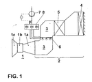
- FIG. 1 schematically illustrates the application of the inventive method with reference to the inflow channel of a gas turbine group 1.
- the gas turbine group shown by way of example has, without limiting the generality, a compressor 1a, a combustion chamber 1b and a turbine 1c.
- the compressor is preceded by a suction 2 for treatment of the intake air supplied in the inflow channel 3.
- an air cleaner 4 and an intake silencer 5 are arranged in the suction region.
- a device 6 for injecting a liquid is arranged in the inflow channel 3. This device is used in particular to introduce finely atomized liquid water droplets in the compressor 1a, where these, as shown initially, evaporate and thereby cause internal cooling of the compressor.
- the injection device 6 must be able to introduce very different liquid mass flows into the inflow channel with sufficient and preferably uniform atomization quality.
- pressure atomizers which advantageously do not require externally induced auxiliary energy, it is mandatory for this purpose to apply a different number of injection nozzles with liquid.
- the admission of the nozzles is realized by a valve block 8 in which a number of shut-off devices selectively release or shut off the flow to particular injectors or groups of injectors.
- a pump 7 delivers the liquid to be injected under pressure to the valve block 8, where the amount of liquid delivered is divided by the shut-off valves on the individual nozzles or nozzle groups.
- a pressure measuring point measures the pressure of the supplied liquid, and the atomization quality of pressure atomizers in the injection device 6 is kept substantially constant via a controlled constant pressure.
- the speed of a centrifugal pump 7 is increased in a pressure reduction, and reduced with increasing pressure, whereby the pressure can be kept constant regardless of the actually enforced mass flow constant, respectively, the mass flow is proportional to the applied nozzle cross sections.
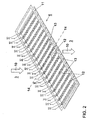
- FIG. 2 shows an exemplary embodiment of the injection device 6.
- tubes 12 are arranged, which in turn carry spray nozzles 13.
- the injection device 6 is designed for a normal to the area of the frame 11 spanned surface oriented air flow 10.
- two tubes are arranged one behind the other in the flow direction. This reduces the obstruction of the flow channel 3, and thus also the pressure losses caused by the injection device.
- the injection nozzles of the downstream pipes are oriented in the direction of the intended flow.
- the injection nozzles of the upstream pipes are at an angle to the direction of flow. The liquid sprayed from these nozzles is injected into the gap between two of the downstream tubes, respectively; This prevents precipitation of the injected liquid on the downstream pipes.
- the entire injector 6 is provided at a certain nominal pressure, which is essentially predetermined by the atomizer nozzles 13, for a given total nominal mass flow.
- a number of nozzles are already combined to form a group.
- Each nozzle tube 12 is associated with a relative partial mass flow, which is determined as the mass flow through the tube under nominal conditions, based on the total mass flow of the injection device 6. Under the - by no means compelling! Assuming that all the nozzles 13 are identical, but which design generally has advantages, this relative partial mass flow is proportional to the number of nozzles 13 arranged on the nozzle tube 12. At an injection mass flow, which is below the total nominal mass flow, only a corresponding proportion of the nozzle tubes is charged with liquid.
- the injection device further has a central axis or axis of symmetry 14.
- the arrangement of the nozzles on each side of the central axis 14 is a mirror image of each other.
- substantially so many tubes are charged with fluid on each side of the axis of symmetry that their cumulated partial mass flows are at least approximately identical on each side of the symmetry axis.
- tubes are charged with liquid, which are distributed as uniformly as possible over the flow cross-section.
- the control is, as mentioned, simplified when each combined a number of tubes into a group and controlled together, that is acted upon together with liquid or just not acted upon, are.
- tubes are grouped into four groups I, II, III, and IV.
- the groups are selected so that the group mass flows of the individual groups are geometrically stepped, in particular un preferred with a grading factor of 2, this of course also includes deviations by a few percent down and up, which in particular by the discretization of the possible and realizable Operamassenstrominkremente are conditional.
- the Group II group mass flow is therefore twice that of Group I, that of Group III is twice that of Group II, and so on.
- the group mass flows thus behave at least approximately like 1: 2: 4: 8.
- a binary group graduation can be set with the switching of only 4 nozzle groups, that is, in a preferably corresponding summary of nozzle tubes to a respective obturator with only 4 shut-off, with substantially constant Zerstäubungsgüte 15 equidistant graded discrete liquid mass flows.
- the group mass flow of the smallest group is 1/15 of the total nominal mass flow; in general, the group mass relative mass flow of the smallest group is determined for N binary stepped groups of the formula 1/2 N-1 .
- Banned groups Liquid mass flow in 1/15 of the total nominal mass flow I 1 II 2 II + I 3 III 4 III + I 5 III + II 6 III + II + I 7 IV 8th IV + I 9 IV + II 10 IV + II + I 11 IV + III 12 IV + III + I 13 IV + III + II 14 IV + III + II + I 15
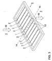
- FIG. 3 shows another example of the embodiment of the invention.
- the injection device 6 shown there has ten tubes 12 with atomization nozzles, not shown. It is based on the following explanations that all tubes carry the same number of identical atomizing nozzles.
- the nozzle tubes are grouped into six groups I to VI. In this case, the relative group mass flow of Group I and VI is 10% each, in Groups II, III, IV, and V each 20%. The grouping makes it possible to set the injection mass flow in 10% increments.
- the groups II, III, IV and V are arranged symmetrically to the center line 14, the groups I and VI asymmetric. that is, when either group I or group VI is charged with liquid without the other of the two groups being simultaneously applied, an asymmetry arises.
- Schematic 1 Impacted groups
- Scheme 2 Impacted groups Liquid mass flow in% of the total nominal mass flow I I 10 II I + VI 20 II + I II + I 30 III + II II + VI I + 40 III + II + I III + II + 1 50 IV + III + II + II + VI I + 60 IV + III + II + I IV + III + II + I 70 V + IV + III + II + III + II + VI I + 80 V + IV + II + III + I V + IV + II + III + I 90 V + IV + III + II + VI I + V + IV + III + II + VI I + 100
- Scheme 2 has lower asymmetries, Scheme 1 requires fewer shifts.
- circuit diagrams shown by no means need to be switched in chronological order, but with advantage all necessary according to a circuit diagram for a target mass flow groups are switched simultaneously.
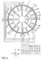
- FIG. 4 shows a further embodiment of an injection device, which can be operated according to the inventive method.
- the device shown here is particularly suitable for use in circular or nearly circular or annular flow cross sections, so in the immediate inlet region of a compressor, in the so-called "Bellmouth".
- the - several - symmetry lines are not shown here for reasons of clarity, but readily apparent to one skilled in the art.
- the atomizing nozzles 13 are arranged on nozzle tubes 12, wherein a part of the nozzle tubes carries nozzles in a radially inner region of the annular inflow channel 3, and carries a part of other part nozzles in a radially outer region.
- the nozzles are arranged at an angular distance of 45 °, in the outer region at an angular distance of 22.5 °, in order to achieve a more homogeneous injection can.
- the tubes are supported by a stiffening ring 15 against each other to prevent flutter or vibration.
- a possible circuit diagram which allows the most homogeneous and symmetrical loading of the gas flow with drops, could be: XII-VI-II-VIII-V-XI-IX-III-X-IV-VII-I, although other switching schemes than may prove suitable.
- the nozzle tubes 12 are arranged in ring-segment-shaped configuration in the annular inflow channel 3.
- the radial distance of the nozzle tubes 12 decreases towards the outside.
- Respectively radially opposite tubes with atomizing nozzles are in turn combined to form a group I, II, III, IV, V, VI and are acted upon together with liquid, whereby asymmetries are again avoided or minimized.
Landscapes
- Engineering & Computer Science (AREA)
- Chemical & Material Sciences (AREA)
- Combustion & Propulsion (AREA)
- Mechanical Engineering (AREA)
- General Engineering & Computer Science (AREA)
- Nozzles (AREA)
Abstract
Claims (16)
- Procédé pour commander l'injection de liquide dans un canal d'amenée (3) d'une machine motrice ou d'une machine de travail au moyen d'un dispositif d'injection (6) qui est prévu pour un débit massique nominal total, et qui présente une pluralité de buses de pulvérisation (12), en particulier des buses de pulvérisation sous pression, lesquelles buses sont disposées de manière répartie sur la section transversale du canal d'amenée, et chaque buse étant conçue pour permettre le débit d'un flux partiel du flux massique nominal total, le dispositif d'injection présentant au moins un axe de symétrie (14), dans lequel procédé, dans le cas d'un flux massique d'injection qui est inférieur au flux massique nominal total, seulement une partie des buses sont sollicitées avec du liquide, caractérisé en ce que pour éviter un écart réduit de la marge au pompage, au moins un certain nombre de buses sont réunies pour former un groupe de buses (I, II ; ..), un groupe de buses étant à chaque fois sollicité conjointement avec du liquide avec un débit de groupe de liquide associé, et
en ce que de chaque côté de l'axe de symétrie (14), est essentiellement sollicité un nombre de buses (13) tel que la somme des flux massiques partiels des buses sollicitées soit identique de chaque côté de l'axe de symétrie. - Procédé selon la revendication 1, caractérisé en ce que de chaque côté de l'axe de symétrie sont sollicitées avec du liquide des buses disposées essentiellement suivant une symétrie spéculaire les unes par rapport aux autres.
- Procédé selon l'une quelconque des revendications précédentes, caractérisé en ce que des buses qui sont disposées de manière réparties aussi uniformément que possible sur la section transversale sont sollicitées avec du fluide.
- Procédé selon l'une quelconque des revendications précédentes, caractérisé en ce qu'au moins un certain nombre de buses de pulvérisation (13) sont disposées sur au moins un tube de buses (12), les buses disposées sur le tube de buses étant sollicitées conjointement avec du liquide.
- Procédé selon l'une quelconque des revendications précédentes, caractérisé en ce qu'à chaque fois un certain nombre de tubes sont réunis en un groupe (I, II, ..), un groupe de tubes étant à chaque fois sollicité conjointement avec du liquide avec un débit de groupe de liquide associé.
- Procédé selon l'une quelconque des revendications 1 à 3 ou 5, caractérisé en ce que des buses et/ou des tubes disposés essentiellement symétriquement par rapport à l'axe de symétrie sont réunis en un groupe devant être sollicité en commun.
- Procédé selon l'une quelconque des revendications 4 à 6, caractérisé en ce que les buses et/ou les tubes sont réunis en groupes de telle sorte que le même flux massique partiel passe à travers chaque groupe en tant que débit de groupe.
- Procédé selon l'une quelconque des revendications 4 à 6, caractérisé en ce que les buses et/ou les tubes sont réunis en groupes et sont sollicités en commun avec du liquide de telle sorte qu'une première partie des groupes présente à chaque fois un premier débit de groupe, et qu'au moins un groupe supplémentaire présente un deuxième débit de groupe qui est inférieur au premier débit de groupe.
- Procédé selon la revendication 8, caractérisé en ce que le deuxième débit de groupe représente 50 % du premier débit de groupe.
- Procédé selon l'une quelconque des revendications 4 à 6, caractérisé en ce que les buses et/ou les tubes sont réunis en groupes et sont sollicités avec du fluide de telle sorte que les débits de groupe des groupes individuels présentent une gradation géométrique.
- Procédé selon la revendication 10, caractérisé en ce que le débit de groupe d'un groupe vaut à chaque fois le double du débit de groupe du groupe plus petit suivant, de telle sorte que les groupes présentent une gradation binaire des débits de groupe.
- Procédé selon l'une quelconque des revendications précédentes, caractérisé en ce que la chute de pression est maintenue constante par le biais des buses d'injection.
- Procédé selon l'une quelconque des revendications précédentes, caractérisé en ce que la pression de admission du liquide est maintenue constante avant l'écoulement à travers les buses d'injection.
- Dispositif pour mettre en oeuvre un procédé selon l'une quelconque des revendications 4 à 13, caractérisé en ce que les buses et/ou les tubes sont connectés à des conduites d'alimentation, toutes les conduites d'alimentation des buses et/ou des tubes d'un groupe étant connectées en un endroit situé en amont et pouvant être commandées par le biais d'un organe d'arrêt commun, et en ce qu'au moins un certain nombre de buses sont réunies en un groupe de buses (I, II ; ..) avec un débit de groupe de liquide associé, et en ce que de chaque côté de l'axe de symétrie (14) sont réunies en un groupe essentiellement un nombre de buses (13) tel que la somme des flux massiques partiels pouvant être injectés à travers ces buses soit identique de chaque côté de l'axe de symétrie.
- Dispositif selon la revendication 14, caractérisé en ce que toutes les buses et/ou les tubes sont identiques.
- Dispositif selon l'une quelconque des revendications 14 ou 15, caractérisé en ce que les buses et/ou les tubes sont disposés de manière équidistante dans le canal d'écoulement.
Applications Claiming Priority (3)
| Application Number | Priority Date | Filing Date | Title |
|---|---|---|---|
| DE10256193A DE10256193A1 (de) | 2002-12-02 | 2002-12-02 | Verfahren zur Steuerung der Flüssigkeitseinspritzung in einen Zuströmkanal einer Kraft- oder Arbeitsmaschine |
| DE10256193 | 2002-12-02 | ||
| PCT/EP2003/050901 WO2004051062A1 (fr) | 2002-12-02 | 2003-11-26 | Procede pour reguler l'injection de liquide dans un canal d'amenee d'un moteur ou d'une machine de travail |
Publications (2)
| Publication Number | Publication Date |
|---|---|
| EP1567756A1 EP1567756A1 (fr) | 2005-08-31 |
| EP1567756B1 true EP1567756B1 (fr) | 2012-08-15 |
Family
ID=32308903
Family Applications (1)
| Application Number | Title | Priority Date | Filing Date |
|---|---|---|---|
| EP03812183A Revoked EP1567756B1 (fr) | 2002-12-02 | 2003-11-26 | Procede pour reguler l'injection de liquide dans un canal d'amenee d'un moteur ou d'une machine de travail |
Country Status (6)
| Country | Link |
|---|---|
| US (1) | US7520137B2 (fr) |
| EP (1) | EP1567756B1 (fr) |
| JP (1) | JP4718838B2 (fr) |
| AU (1) | AU2003300571A1 (fr) |
| DE (1) | DE10256193A1 (fr) |
| WO (1) | WO2004051062A1 (fr) |
Families Citing this family (40)
| Publication number | Priority date | Publication date | Assignee | Title |
|---|---|---|---|---|
| GB2382848A (en) | 2001-12-06 | 2003-06-11 | Alstom | Gas turbine wet compression |
| GB2382847A (en) | 2001-12-06 | 2003-06-11 | Alstom | Gas turbine wet compression |
| DE10256193A1 (de) | 2002-12-02 | 2004-06-09 | Alstom Technology Ltd | Verfahren zur Steuerung der Flüssigkeitseinspritzung in einen Zuströmkanal einer Kraft- oder Arbeitsmaschine |
| DE10340177A1 (de) * | 2003-09-01 | 2005-03-31 | Alstom Technology Ltd | Zerstäubungs- und Eindüsensystem, und Verfahren zum Betrieb |
| WO2005121509A1 (fr) * | 2004-06-14 | 2005-12-22 | Gas Turbine Efficiency Ab | Systeme et dispositifs de collecte et de traitement d'eaux usees provenant du nettoyage de moteur |
| US7703272B2 (en) * | 2006-09-11 | 2010-04-27 | Gas Turbine Efficiency Sweden Ab | System and method for augmenting turbine power output |
| DE102007015309B4 (de) | 2007-03-27 | 2023-01-05 | Ansaldo Energia Switzerland AG | Betriebsverfahren für eine Turbogruppe |
| US8360711B2 (en) * | 2007-08-22 | 2013-01-29 | General Electric Company | Apparatus and method for pressurized inlet evaporative cooling of gas turbine engines |
| US8291714B2 (en) | 2007-12-06 | 2012-10-23 | Rolls-Royce Power Endgineering PLC | Radial staging method and configuration of a liquid injection system for power plants |
| US8001789B2 (en) * | 2008-03-26 | 2011-08-23 | Alstom Technologies Ltd., Llc | Utilizing inlet bleed heat to improve mixing and engine turndown |
| DE102008032565A1 (de) | 2008-07-11 | 2010-01-14 | Rolls-Royce Deutschland Ltd & Co Kg | Brennstoffzufuhrsystem für ein Gasturbinentriebwerk |
| US8167980B2 (en) * | 2008-08-28 | 2012-05-01 | General Electric Company | Filtration system for gas turbines |
| US8182587B2 (en) * | 2008-08-28 | 2012-05-22 | General Electric Company | Filtration system for gas turbines |
| US20100326083A1 (en) * | 2009-06-26 | 2010-12-30 | Robert Bland | Spray system, power augmentation system for engine containing spray system and method of humidifying air |
| US8671696B2 (en) * | 2009-07-10 | 2014-03-18 | Leonard M. Andersen | Method and apparatus for increasing thrust or other useful energy output of a device with a rotating element |
| US9016293B2 (en) * | 2009-08-21 | 2015-04-28 | Gas Turbine Efficiency Sweden Ab | Staged compressor water wash system |
| US8978386B2 (en) * | 2010-09-30 | 2015-03-17 | Mitsubishi Hitachi Power Systems, Ltd. | Gas turbine system, control device for gas turbine system, and control method for gas turbine system |
| US8632299B2 (en) | 2010-11-30 | 2014-01-21 | Pratt & Whitney Canada Corp. | Engine case with wash system |
| US9441542B2 (en) | 2011-09-20 | 2016-09-13 | General Electric Company | Ultrasonic water atomization system for gas turbine inlet cooling and wet compression |
| US8932004B2 (en) * | 2011-11-08 | 2015-01-13 | General Electric Company | Inlet bleed heat system |
| US8926265B2 (en) * | 2011-11-08 | 2015-01-06 | General Electric Company | Inlet bleed heat system |
| US9816391B2 (en) | 2012-11-07 | 2017-11-14 | General Electric Company | Compressor wash system with spheroids |
| JP6180145B2 (ja) | 2013-03-26 | 2017-08-16 | 三菱日立パワーシステムズ株式会社 | 吸気冷却装置 |
| US20140360217A1 (en) * | 2013-06-11 | 2014-12-11 | Bha Altair, Llc | Cooling system for use in a turbine assembly and method of assembly |
| US9951646B2 (en) | 2013-07-01 | 2018-04-24 | General Electric Company | Gas turbine on-line water wash system and method |
| EP2824285B1 (fr) * | 2013-07-11 | 2016-03-16 | Alstom Technology Ltd | Turbine à gaz comprenant un système de contrôle du flux d'entrée |
| US9359951B2 (en) * | 2013-09-06 | 2016-06-07 | General Electric Company | Inlet bleed heat system and related method for a compact gas turbine inlet |
| EP2857656A1 (fr) * | 2013-10-01 | 2015-04-08 | Alstom Technology Ltd | Turbine à gaz avec système de refroidissement d'air de refroidissement et procédé de fonctionnement d'une turbine à gaz à faible charge partielle |
| JP2015090090A (ja) * | 2013-11-05 | 2015-05-11 | 三菱日立パワーシステムズ株式会社 | 吸気噴霧装置およびガスタービン設備 |
| US20150159509A1 (en) * | 2013-12-06 | 2015-06-11 | General Electric Company | Method and System for Dispensing Gas Turbine Anticorrosive Protection |
| US10557413B1 (en) * | 2014-11-26 | 2020-02-11 | Caldwell Tanks, Inc. | Systems and methods for controlling liquid flow to a turbine fogging array |
| KR101835421B1 (ko) * | 2015-12-31 | 2018-03-08 | 한국항공우주연구원 | 습식 압축용 환형 분사 장치 |
| US20180135467A1 (en) * | 2016-11-14 | 2018-05-17 | General Electric Company | Cooling of gas turbine at varying loads |
| US10677164B2 (en) | 2016-11-15 | 2020-06-09 | General Electric Company | Cooling system for a turbine engine |
| US20180306112A1 (en) * | 2017-04-20 | 2018-10-25 | General Electric Company | System and Method for Regulating Flow in Turbomachines |
| US11022038B2 (en) | 2017-05-04 | 2021-06-01 | General Electric Company | Compressor circumferential fluid distribution system |
| WO2019075339A1 (fr) * | 2017-10-12 | 2019-04-18 | Prodew, Inc. | Systèmes d'humidification |
| WO2022182730A1 (fr) * | 2021-02-23 | 2022-09-01 | Stellar Energy Americas, Inc. | Systèmes de refroidissement d'air d'entrée de turbine avec récupération d'eau de condensat |
| US20250122833A1 (en) * | 2023-10-17 | 2025-04-17 | Ge Infrastructure Technology Llc | Airless sprint & water wash system |
| US12134984B1 (en) * | 2023-11-17 | 2024-11-05 | Rtx Corporation | Fluidic compressor inlet guide vanes |
Family Cites Families (142)
| Publication number | Priority date | Publication date | Assignee | Title |
|---|---|---|---|---|
| US986308A (en) | 1907-06-15 | 1911-03-07 | Russell A Alger | Method and apparatus for generating motive power. |
| US1265650A (en) | 1917-04-14 | 1918-05-07 | Escher Wyss Maschf Ag | Cooling device in multistage centrifugal compressors. |
| US1384570A (en) | 1918-07-10 | 1921-07-12 | William Scully | System of supplying an explosive mixture to engines and turbines |
| US2115338A (en) | 1932-12-15 | 1938-04-26 | Milo Ab | Gas turbine system |
| US2219994A (en) | 1937-09-24 | 1940-10-29 | Bbc Brown Boveri & Cie | Gas turbine plant and regulating system therefor |
| US2322717A (en) | 1939-08-10 | 1943-06-22 | Nettel Friedrich | Apparatus for combustion turbines |
| US2365616A (en) | 1940-11-28 | 1944-12-19 | Bbc Brown Boveri & Cie | Regulating apparatus for gas turbine plants |
| US2438998A (en) | 1942-09-15 | 1948-04-06 | Dehavilland Aircraft | Means for controlling the temperature of gases |
| US2489683A (en) | 1943-11-19 | 1949-11-29 | Edward A Stalker | Turbine |
| US2469678A (en) | 1943-12-18 | 1949-05-10 | Edwin T Wyman | Combination steam and gas turbine |
| US2469679A (en) | 1944-07-13 | 1949-05-10 | Edwin T Wyman | Gas turbine |
| US2648196A (en) | 1947-03-18 | 1953-08-11 | Experiment Inc | Ram jet burner with aqueous injection to promote smooth burning |
| US2657530A (en) | 1947-11-21 | 1953-11-03 | Niles Bement Pond Co | Control apparatus for turbojet engines |
| US2686631A (en) | 1948-05-08 | 1954-08-17 | United Aircraft Corp | Coolant injection system for gas turbines |
| US2689452A (en) | 1949-12-02 | 1954-09-21 | United Aircraft Corp | Device for increasing the thrust of turbojet engines |
| US2678531A (en) | 1951-02-21 | 1954-05-18 | Chemical Foundation Inc | Gas turbine process with addition of steam |
| US2727734A (en) * | 1951-06-14 | 1955-12-20 | Johnson Co C S | Method of and apparatus for cooling concrete aggregates |
| US2863282A (en) | 1953-01-09 | 1958-12-09 | United Aircraft Corp | Water injection system for gas turbine power plant |
| US2974482A (en) | 1955-04-25 | 1961-03-14 | Curtiss Wright Corp | Coolant injection system for engines |
| US2927423A (en) | 1956-02-09 | 1960-03-08 | Henryk U Wisniowski | Prevention of screeching combustion in jet engines |
| US2869670A (en) | 1956-10-01 | 1959-01-20 | Gen Motors Corp | Intake silencer |
| US2941356A (en) | 1957-03-01 | 1960-06-21 | United Aircraft Corp | Variable pressure wave absorption for combustion chambers |
| US3100964A (en) | 1959-11-25 | 1963-08-20 | Gen Motors Corp | Water injection system for a multistage compressor |
| DE1239888B (de) | 1961-12-15 | 1967-05-03 | Prvni Brnenska Strojirna | Gasdampfturbinenanlage |
| US3359737A (en) | 1965-01-26 | 1967-12-26 | United Aircraft Corp | Combustion instabillity reduction device |
| US3353360A (en) | 1966-02-18 | 1967-11-21 | Foster Wheeler Corp | Power plant with steam injection |
| FR1563749A (fr) | 1967-12-20 | 1969-04-18 | ||
| US3623668A (en) | 1968-03-04 | 1971-11-30 | Gen Electric | Wash manifold |
| US3630030A (en) | 1970-02-09 | 1971-12-28 | Donaldson Co Inc | Liquid-attenuated exhaust system |
| US3894691A (en) | 1970-12-31 | 1975-07-15 | Thomas R Mee | Nozzle for producing small droplets of controlled size |
| US3815356A (en) | 1971-03-10 | 1974-06-11 | Trw Inc | Foam cooling and acoustic damping of exhaust gases produced by an internal combustion engine |
| US3693347A (en) | 1971-05-12 | 1972-09-26 | Gen Electric | Steam injection in gas turbines having fixed geometry components |
| US3736074A (en) | 1972-04-20 | 1973-05-29 | Worthington Cei | Inlet, filter and noise suppressor enclosure for compressing apparatus |
| CH569861A5 (fr) | 1974-04-09 | 1975-11-28 | Bbc Sulzer Turbomaschinen | |
| CH584837A5 (fr) | 1974-11-22 | 1977-02-15 | Sulzer Ag | |
| US3936215A (en) | 1974-12-20 | 1976-02-03 | United Technologies Corporation | Turbine vane cooling |
| FR2370171A1 (fr) | 1976-11-05 | 1978-06-02 | Snecma | Procede et dispositif pour la diminution du bruit des turbomachines |
| US4196020A (en) * | 1978-11-15 | 1980-04-01 | Avco Corporation | Removable wash spray apparatus for gas turbine engine |
| US4311439A (en) | 1979-10-17 | 1982-01-19 | Stofen Kenneth A | Compressed air system |
| US4281511A (en) | 1980-02-27 | 1981-08-04 | Neale Abas B | Hydro-flow supra-turbine engine |
| US4260350A (en) * | 1980-04-16 | 1981-04-07 | Fiber Industries, Inc. | Filter for high viscosity liquids |
| US4418527A (en) | 1980-04-21 | 1983-12-06 | Schlom Leslie A | Precooler for gas turbines |
| JPS5886441U (ja) | 1981-12-07 | 1983-06-11 | 三菱重工業株式会社 | 吸気予冷ガスタ−ビン |
| JPS58117306A (ja) | 1981-12-29 | 1983-07-12 | Hitachi Ltd | コンバインドプラント |
| US4478553A (en) | 1982-03-29 | 1984-10-23 | Mechanical Technology Incorporated | Isothermal compression |
| US4569195A (en) * | 1984-04-27 | 1986-02-11 | General Electric Company | Fluid injection gas turbine engine and method for operating |
| US4572428A (en) | 1985-01-08 | 1986-02-25 | Herrmidifier Company, Inc. | In duct atomizing humidification and evaporative cooling system |
| JPS61283723A (ja) | 1985-06-10 | 1986-12-13 | Toyota Motor Corp | インタク−ラ冷却装置 |
| US4928478A (en) | 1985-07-22 | 1990-05-29 | General Electric Company | Water and steam injection in cogeneration system |
| US4702074A (en) | 1985-07-30 | 1987-10-27 | Michael Munk | Internal combustion engine system with fog injection and heat exchange |
| US4731990A (en) | 1985-07-30 | 1988-03-22 | Michael Munk | Internal combustion engine system and method with reduced noxious emissions |
| US4667465A (en) | 1985-07-30 | 1987-05-26 | Michael Munk | Internal combustion engine system and method with reduced noxious emissions |
| US5011540A (en) | 1986-12-24 | 1991-04-30 | Mcdermott Peter | Method and apparatus for cleaning a gas turbine engine |
| US5273395A (en) | 1986-12-24 | 1993-12-28 | Rochem Technical Services Holding Ag | Apparatus for cleaning a gas turbine engine |
| JPS63248931A (ja) | 1987-04-06 | 1988-10-17 | Hitachi Ltd | 圧縮機入口空気水分の氷結防止法 |
| JPH0610702B2 (ja) | 1987-11-18 | 1994-02-09 | インターナショナル・ビジネス・マシーンズ・コーポレーション | カラー液晶表示装置およびその製造方法 |
| US4949544A (en) | 1988-12-06 | 1990-08-21 | General Electric Company | Series intercooler |
| US5083423A (en) | 1989-01-11 | 1992-01-28 | Stewart & Stevenson Services, Inc. | Apparatus and method for optimizing the air inlet temperature of gas turbines |
| JPH0797933B2 (ja) | 1989-01-17 | 1995-10-25 | 株式会社クボタ | コンバイン |
| CH681381A5 (fr) | 1990-02-14 | 1993-03-15 | Turbotect Ag | |
| US5203161A (en) | 1990-10-30 | 1993-04-20 | Lehto John M | Method and arrangement for cooling air to gas turbine inlet |
| US5191767A (en) | 1990-11-07 | 1993-03-09 | Mistop, Inc. | Gas turbine air handling system |
| US5282726A (en) | 1991-06-21 | 1994-02-01 | Praxair Technology, Inc. | Compressor supercharger with evaporative cooler |
| JP3181084B2 (ja) | 1992-01-21 | 2001-07-03 | 東北電力株式会社 | ガスタービン燃焼用空気冷却装置 |
| US5353585A (en) | 1992-03-03 | 1994-10-11 | Michael Munk | Controlled fog injection for internal combustion system |
| DE4210544A1 (de) | 1992-03-31 | 1993-10-07 | Asea Brown Boveri | Gasturbinenanlage |
| US5306116A (en) | 1992-04-10 | 1994-04-26 | Ingersoll-Rand Company | Surge control and recovery for a centrifugal compressor |
| US5537813A (en) | 1992-12-08 | 1996-07-23 | Carolina Power & Light Company | Gas turbine inlet air combined pressure boost and cooling method and apparatus |
| US5326254A (en) | 1993-02-26 | 1994-07-05 | Michael Munk | Fog conditioned flue gas recirculation for burner-containing apparatus |
| IL110361A (en) | 1993-07-22 | 2003-03-12 | Ormat Ind Ltd | Method of and apparatus for augmenting power produced by gas turbines |
| EP0646704B1 (fr) | 1993-09-06 | 1997-11-26 | Asea Brown Boveri Ag | Procédé de régulation d'une installation pour turbine à gaz équipée de deux chambres de combustion |
| US5463873A (en) | 1993-12-06 | 1995-11-07 | Cool Fog Systems, Inc. | Method and apparatus for evaporative cooling of air leading to a gas turbine engine |
| US5496012A (en) | 1994-01-03 | 1996-03-05 | C&W Fabricators, Inc. | Industrial roll-up damper |
| US5560195A (en) | 1995-02-13 | 1996-10-01 | General Electric Co. | Gas turbine inlet heating system using jet blower |
| DE19508018A1 (de) | 1995-03-07 | 1996-09-12 | Abb Management Ag | Verfahren zum Betrieb einer Kraftwerksanlage |
| US5790972A (en) | 1995-08-24 | 1998-08-04 | Kohlenberger; Charles R. | Method and apparatus for cooling the inlet air of gas turbine and internal combustion engine prime movers |
| DE19531562A1 (de) | 1995-08-28 | 1997-03-06 | Abb Management Ag | Verfahren zum Betrieb einer Kraftwerksanlage |
| US5669217A (en) | 1995-09-25 | 1997-09-23 | Anderson; J. Hilbert | Method and apparatus for intercooling gas turbines |
| DE19536839A1 (de) | 1995-10-02 | 1997-04-30 | Abb Management Ag | Verfahren zum Betrieb einer Kraftwerksanlage |
| DE19539774A1 (de) | 1995-10-26 | 1997-04-30 | Asea Brown Boveri | Zwischengekühlter Verdichter |
| JP2877098B2 (ja) | 1995-12-28 | 1999-03-31 | 株式会社日立製作所 | ガスタービン,コンバインドサイクルプラント及び圧縮機 |
| DE19604664A1 (de) | 1996-02-09 | 1997-08-14 | Asea Brown Boveri | Verfahren zum Betrieb einer Kraftwerksanlage |
| DE19609912A1 (de) | 1996-03-14 | 1997-09-18 | Asea Brown Boveri | Verfahren zum Betrieb einer Kraftwerksanlage |
| DE19615911A1 (de) | 1996-04-22 | 1997-10-23 | Asea Brown Boveri | Verfahren zum Betrieb einer Kombianlage |
| US5930990A (en) * | 1996-05-14 | 1999-08-03 | The Dow Chemical Company | Method and apparatus for achieving power augmentation in gas turbines via wet compression |
| US5867977A (en) | 1996-05-14 | 1999-02-09 | The Dow Chemical Company | Method and apparatus for achieving power augmentation in gas turbines via wet compression |
| JP3469018B2 (ja) * | 1996-12-10 | 2003-11-25 | 三菱重工業株式会社 | ガスタービンの吸気冷却装置 |
| DE19651882A1 (de) | 1996-12-13 | 1998-06-18 | Asea Brown Boveri | Verfahren zur Frequenzstützung beim Betrieb einer Kraftwerksanlage |
| US6179735B1 (en) * | 1997-02-24 | 2001-01-30 | Mcmahon Marshal | Apparatus and method for maintaining differential tensions in the strings of a sporting racket |
| US6389799B1 (en) | 1997-04-22 | 2002-05-21 | Hitachi, Ltd. | Gas turbine Installation |
| US6256976B1 (en) | 1997-06-27 | 2001-07-10 | Hitachi, Ltd. | Exhaust gas recirculation type combined plant |
| SG104914A1 (en) | 1997-06-30 | 2004-07-30 | Hitachi Ltd | Gas turbine |
| USRE38831E1 (en) | 1997-06-30 | 2005-10-18 | Hitachi, Ltd. | Gas turbine having water spray injection control |
| USRE39092E1 (en) | 1997-06-30 | 2006-05-09 | Hitachi, Ltd. | Gas turbine with water injection |
| JP3502239B2 (ja) * | 1997-06-30 | 2004-03-02 | 株式会社日立製作所 | ガスタービンプラント |
| DE59709403D1 (de) | 1997-07-25 | 2003-04-03 | Alstom Switzerland Ltd | Verfahren zum Betrieb einer Kraftwerksanlage |
| DE59707371D1 (de) | 1997-08-25 | 2002-07-04 | Alstom | Gasturbine mit Wärmerückgewinnungserzeuger von überhitztem Dampf zum Einspritzen in die Brennkammer und von Sattdampf zum Kühlen und dann Einspritzen in die Brennkammer |
| DE59710734D1 (de) | 1997-12-08 | 2003-10-16 | Alstom Switzerland Ltd | Verfahren zur Regelung einer Gasturbogruppe |
| DE59711519D1 (de) | 1997-12-17 | 2004-05-19 | Alstom Technology Ltd Baden | Verfahren zum Betrieb einer Gasturbogruppe |
| DE59710790D1 (de) | 1997-12-17 | 2003-10-30 | Alstom Switzerland Ltd | Verfahren zum Betrieb einer Gasturbogruppe |
| EP0924406A1 (fr) | 1997-12-18 | 1999-06-23 | Asea Brown Boveri AG | Turbine à gaz avec un générateur de vapeur et un récupérateur disposés en parallèle dans les gaz d'échappement |
| JPH11324710A (ja) | 1998-05-20 | 1999-11-26 | Hitachi Ltd | ガスタービン発電プラント |
| NL1011383C2 (nl) | 1998-06-24 | 1999-12-27 | Kema Nv | Inrichting voor het comprimeren van een gasvormig medium en systemen die een dergelijke inrichting omvatten. |
| US6470667B1 (en) * | 1998-07-24 | 2002-10-29 | General Electric Company | Methods and apparatus for water injection in a turbine engine |
| US6484508B2 (en) | 1998-07-24 | 2002-11-26 | General Electric Company | Methods for operating gas turbine engines |
| EP0978635B1 (fr) | 1998-08-05 | 2003-05-28 | ALSTOM (Switzerland) Ltd | Procédé pour refroidir les structures thermiquement chargées d'une centrale thermique |
| DE19852060A1 (de) | 1998-11-11 | 2000-05-25 | Steag Ag | Verfahren und Vorrichtung zum Konditionieren von Zuluft für eine Kraft- oder Arbeitsmaschine |
| DE19900026B4 (de) | 1999-01-02 | 2016-01-21 | Alstom Technology Ltd. | Gasturbine mit Dampfeindüsung |
| US6173564B1 (en) | 1999-02-22 | 2001-01-16 | The Dow Chemical Company | Apparatus for monitoring wet compression gas turbine power augmentation-related casing distortions |
| JP3538807B2 (ja) * | 1999-04-05 | 2004-06-14 | 吉秀 中村 | ガスタービンプラント |
| US6250064B1 (en) | 1999-05-07 | 2001-06-26 | General Electric Co. | Gas turbine inlet air integrated water saturation and supersaturation system and related process |
| DE19952885A1 (de) | 1999-11-03 | 2001-05-10 | Alstom Power Schweiz Ag Baden | Verfahren und Betrieb einer Kraftwerksanlage |
| DE19961383A1 (de) | 1999-12-20 | 2001-06-21 | Alstom Power Schweiz Ag Baden | Verfahren zum Betrieb einer Kraftwerksanlage |
| JP3691711B2 (ja) * | 2000-02-21 | 2005-09-07 | 株式会社日立製作所 | ガスタービンプラント |
| JP3750474B2 (ja) | 2000-03-08 | 2006-03-01 | 株式会社日立製作所 | 熱電併給設備およびその運転方法 |
| JP2001342847A (ja) * | 2000-05-30 | 2001-12-14 | Hitachi Ltd | ガスタービンとガスタービン発電システム |
| US6553768B1 (en) * | 2000-11-01 | 2003-04-29 | General Electric Company | Combined water-wash and wet-compression system for a gas turbine compressor and related method |
| US6478289B1 (en) * | 2000-11-06 | 2002-11-12 | General Electric Company | Apparatus and methods for controlling the supply of water mist to a gas-turbine compressor |
| US6634165B2 (en) | 2000-12-28 | 2003-10-21 | General Electric Company | Control system for gas turbine inlet-air water-saturation and supersaturation system |
| US6715916B2 (en) | 2001-02-08 | 2004-04-06 | General Electric Company | System and method for determining gas turbine firing and combustion reference temperatures having correction for water content in fuel |
| WO2002084091A1 (fr) | 2001-04-09 | 2002-10-24 | Hitachi, Ltd. | Générateur de puissance à turbine à gaz |
| JP2002322916A (ja) * | 2001-04-26 | 2002-11-08 | Toshiba Corp | ガスタービン吸気冷却装置 |
| US20050141991A1 (en) | 2001-10-17 | 2005-06-30 | Frutschi Hans U. | Method for conditioning a compressor airflow and device therefor |
| US6523346B1 (en) | 2001-11-02 | 2003-02-25 | Alstom (Switzerland) Ltd | Process for controlling the cooling air mass flow of a gas turbine set |
| US6640550B2 (en) | 2001-11-02 | 2003-11-04 | Alstom (Switzerland) Ltd | Gas turbo-group with cooling air system |
| US6644012B2 (en) | 2001-11-02 | 2003-11-11 | Alston (Switzerland) Ltd | Gas turbine set |
| DE10153911B4 (de) | 2001-11-02 | 2010-08-19 | Alstom Technology Ltd. | Befestigungsmittel für Einspritzdüsen in einem Luftansaugkanal einer Strömungsmaschine |
| JP2005518490A (ja) | 2001-11-19 | 2005-06-23 | アルストム テクノロジー リミテッド | ガスタービンのための圧縮機 |
| GB2382847A (en) * | 2001-12-06 | 2003-06-11 | Alstom | Gas turbine wet compression |
| GB2382848A (en) | 2001-12-06 | 2003-06-11 | Alstom | Gas turbine wet compression |
| AU2002347121A1 (en) | 2002-01-07 | 2003-07-24 | Alstom Technology Ltd. | Method for operating a gas turbine group |
| AU2003205939A1 (en) | 2002-02-19 | 2003-09-09 | Alstom Technology Ltd | Turboblower and method for operating such a turboblower |
| DE10207197A1 (de) | 2002-02-21 | 2003-09-04 | Alstom Switzerland Ltd | Hochdruckeinspritzdüse, insbesondere für den Einsatz als Explosionszerstäuber |
| DE10254721A1 (de) | 2002-11-23 | 2004-06-03 | Alstom (Switzerland) Ltd. | Vorrichtung zur Flüssigkeitseinspritzung in einen Strömungskanal |
| DE10254825A1 (de) | 2002-11-25 | 2004-06-03 | Alstom Technology Ltd | Wassersprühvorrichtung für Gasturbinen |
| DE10254824A1 (de) | 2002-11-25 | 2004-06-09 | Alstom Technology Ltd | Ansaugschalldämpfer für Gasturbinen |
| DE10256193A1 (de) | 2002-12-02 | 2004-06-09 | Alstom Technology Ltd | Verfahren zur Steuerung der Flüssigkeitseinspritzung in einen Zuströmkanal einer Kraft- oder Arbeitsmaschine |
| US6935119B2 (en) | 2003-03-14 | 2005-08-30 | General Electric Company | Methods for operating gas turbine engines |
| DE10333208A1 (de) | 2003-07-22 | 2005-03-31 | Alstom Technology Ltd | Verfahren zum Betrieb einer luftatmenden Kraftmaschine |
| DE10340177A1 (de) | 2003-09-01 | 2005-03-31 | Alstom Technology Ltd | Zerstäubungs- und Eindüsensystem, und Verfahren zum Betrieb |
| JP4100316B2 (ja) | 2003-09-30 | 2008-06-11 | 株式会社日立製作所 | ガスタービン設備 |
| US6938405B2 (en) * | 2003-11-13 | 2005-09-06 | General Electric Company | Spray nozzle grid configuration for gas turbine inlet misting system |
-
2002
- 2002-12-02 DE DE10256193A patent/DE10256193A1/de not_active Ceased
-
2003
- 2003-11-26 WO PCT/EP2003/050901 patent/WO2004051062A1/fr not_active Ceased
- 2003-11-26 AU AU2003300571A patent/AU2003300571A1/en not_active Abandoned
- 2003-11-26 EP EP03812183A patent/EP1567756B1/fr not_active Revoked
- 2003-11-26 JP JP2004556336A patent/JP4718838B2/ja not_active Expired - Fee Related
-
2005
- 2005-06-02 US US11/142,328 patent/US7520137B2/en not_active Expired - Fee Related
Also Published As
| Publication number | Publication date |
|---|---|
| US7520137B2 (en) | 2009-04-21 |
| EP1567756A1 (fr) | 2005-08-31 |
| DE10256193A1 (de) | 2004-06-09 |
| WO2004051062A1 (fr) | 2004-06-17 |
| US20050279101A1 (en) | 2005-12-22 |
| JP4718838B2 (ja) | 2011-07-06 |
| AU2003300571A1 (en) | 2004-06-23 |
| JP2006508294A (ja) | 2006-03-09 |
Similar Documents
| Publication | Publication Date | Title |
|---|---|---|
| EP1567756B1 (fr) | Procede pour reguler l'injection de liquide dans un canal d'amenee d'un moteur ou d'une machine de travail | |
| DE69427059T2 (de) | Brennstoffablassvorrichtung für Brennstoffeinspritzdüse | |
| DE69921336T2 (de) | Kontrollsysteme und verfahren zur wassereinspritzung in turbomaschinen | |
| DE3514718C2 (de) | Gasturbinenanlage und Verfahren zu ihrem Betrieb | |
| EP0646705B1 (fr) | Procédé pour produire des régimes de fonctionnement partiel dans une installation pour turbine à gaz | |
| DE102008002987B4 (de) | Verfahren und Vorrichtung zum Zuführen von Druck für die Sprühvernebelung durch einen Ansaugluft-Temperaturdämpfer von Gasturbinen | |
| EP1682750B1 (fr) | Centrale electrique | |
| EP1704313B1 (fr) | Procede pour faire fonctionner une centrale electrique | |
| CH705323A1 (de) | Verfahren zum Einspritzen von Wasser in einen mehrstufigen Axialverdichter einer Gasturbine. | |
| EP1084327A1 (fr) | Turbine a gaz ainsi que procede pour le refroidissement d'un etage de turbine | |
| DE102012011294A1 (de) | Verfahren zum Kühlen einer Gasturbinenanlage sowie Gasturbinenanlage zur Durchführung des Verfahrens | |
| DE2321379A1 (de) | Selbstkompensierender stroemungsaufteiler fuer ein dampf-injektionssystem fuer gasturbinen | |
| EP2565391A1 (fr) | Dispositif de nettoyage d'une turbine à gaz d'échappement, et turbine à gaz d'échappement, turbine utilitaire et turbocompresseur à gaz d'échappement associés | |
| CH706150A1 (de) | Verfahren zum Betriebe eines Gasturbinenkraftwerkes mit Abgasrezirkulation sowie Gasturbinentriebwerk. | |
| EP1716327B1 (fr) | Dispositif de refoulement | |
| CH705822A1 (de) | Axialverdichter für eine Strömungsmaschine, insbesondere eine Gasturbine. | |
| DD153718A1 (de) | Arbeitsverfahren fuer eine selbstzuendende brennkraftmaschine | |
| EP0043908B1 (fr) | Injecteur pour injection continue de carburant | |
| DE102012224009A1 (de) | Verfahren zum Betreiben einer Gasturbine | |
| WO2005098217A1 (fr) | Procede et dispositif pour transporter un liquide | |
| EP3058302A1 (fr) | Accumulateur de chaleur comportant une partie diffuseur | |
| CH707578A2 (de) | Brennereinrichtung mit Zentralteil-Brennstoffstufung. | |
| WO2005045213A1 (fr) | Procede pour faire fonctionner un dispositif de pulverisation dans un groupe turbine a gaz | |
| AT522363B1 (de) | Prüfstand | |
| DE102004051260A1 (de) | Gasturbogruppe |
Legal Events
| Date | Code | Title | Description |
|---|---|---|---|
| PUAI | Public reference made under article 153(3) epc to a published international application that has entered the european phase |
Free format text: ORIGINAL CODE: 0009012 |
|
| 17P | Request for examination filed |
Effective date: 20050518 |
|
| AK | Designated contracting states |
Kind code of ref document: A1 Designated state(s): AT BE BG CH CY CZ DE DK EE ES FI FR GB GR HU IE IT LI LU MC NL PT RO SE SI SK TR |
|
| AX | Request for extension of the european patent |
Extension state: AL LT LV MK |
|
| DAX | Request for extension of the european patent (deleted) | ||
| 17Q | First examination report despatched |
Effective date: 20080228 |
|
| GRAP | Despatch of communication of intention to grant a patent |
Free format text: ORIGINAL CODE: EPIDOSNIGR1 |
|
| RTI1 | Title (correction) |
Free format text: METHOD FOR CONTROLLING THE INJECTION OF LIQUID INTO AN INFLOW CHANNEL OF A PRIME MOVER OR MACHINE |
|
| GRAS | Grant fee paid |
Free format text: ORIGINAL CODE: EPIDOSNIGR3 |
|
| GRAA | (expected) grant |
Free format text: ORIGINAL CODE: 0009210 |
|
| AK | Designated contracting states |
Kind code of ref document: B1 Designated state(s): AT BE BG CH CY CZ DE DK EE ES FI FR GB GR HU IE IT LI LU MC NL PT RO SE SI SK TR |
|
| REG | Reference to a national code |
Ref country code: GB Ref legal event code: FG4D Free format text: NOT ENGLISH Ref country code: CH Ref legal event code: EP Ref country code: AT Ref legal event code: REF Ref document number: 570974 Country of ref document: AT Kind code of ref document: T Effective date: 20120815 |
|
| REG | Reference to a national code |
Ref country code: DE Ref legal event code: R081 Ref document number: 50314463 Country of ref document: DE Owner name: GENERAL ELECTRIC TECHNOLOGY GMBH, CH Free format text: FORMER OWNER: ALSTOM TECHNOLOGY LTD., BADEN, CH Ref country code: DE Ref legal event code: R081 Ref document number: 50314463 Country of ref document: DE Owner name: ANSALDO ENERGIA IP UK LIMITED, GB Free format text: FORMER OWNER: ALSTOM TECHNOLOGY LTD., BADEN, CH |
|
| REG | Reference to a national code |
Ref country code: IE Ref legal event code: FG4D Free format text: LANGUAGE OF EP DOCUMENT: GERMAN |
|
| REG | Reference to a national code |
Ref country code: DE Ref legal event code: R096 Ref document number: 50314463 Country of ref document: DE Effective date: 20121011 |
|
| REG | Reference to a national code |
Ref country code: NL Ref legal event code: VDEP Effective date: 20120815 |
|
| PG25 | Lapsed in a contracting state [announced via postgrant information from national office to epo] |
Ref country code: FI Free format text: LAPSE BECAUSE OF FAILURE TO SUBMIT A TRANSLATION OF THE DESCRIPTION OR TO PAY THE FEE WITHIN THE PRESCRIBED TIME-LIMIT Effective date: 20120815 Ref country code: CY Free format text: LAPSE BECAUSE OF FAILURE TO SUBMIT A TRANSLATION OF THE DESCRIPTION OR TO PAY THE FEE WITHIN THE PRESCRIBED TIME-LIMIT Effective date: 20120815 |
|
| PG25 | Lapsed in a contracting state [announced via postgrant information from national office to epo] |
Ref country code: GR Free format text: LAPSE BECAUSE OF FAILURE TO SUBMIT A TRANSLATION OF THE DESCRIPTION OR TO PAY THE FEE WITHIN THE PRESCRIBED TIME-LIMIT Effective date: 20121116 Ref country code: PT Free format text: LAPSE BECAUSE OF FAILURE TO SUBMIT A TRANSLATION OF THE DESCRIPTION OR TO PAY THE FEE WITHIN THE PRESCRIBED TIME-LIMIT Effective date: 20121217 Ref country code: SE Free format text: LAPSE BECAUSE OF FAILURE TO SUBMIT A TRANSLATION OF THE DESCRIPTION OR TO PAY THE FEE WITHIN THE PRESCRIBED TIME-LIMIT Effective date: 20120815 Ref country code: SI Free format text: LAPSE BECAUSE OF FAILURE TO SUBMIT A TRANSLATION OF THE DESCRIPTION OR TO PAY THE FEE WITHIN THE PRESCRIBED TIME-LIMIT Effective date: 20120815 |
|
| PG25 | Lapsed in a contracting state [announced via postgrant information from national office to epo] |
Ref country code: NL Free format text: LAPSE BECAUSE OF FAILURE TO SUBMIT A TRANSLATION OF THE DESCRIPTION OR TO PAY THE FEE WITHIN THE PRESCRIBED TIME-LIMIT Effective date: 20120815 |
|
| PG25 | Lapsed in a contracting state [announced via postgrant information from national office to epo] |
Ref country code: CZ Free format text: LAPSE BECAUSE OF FAILURE TO SUBMIT A TRANSLATION OF THE DESCRIPTION OR TO PAY THE FEE WITHIN THE PRESCRIBED TIME-LIMIT Effective date: 20120815 Ref country code: EE Free format text: LAPSE BECAUSE OF FAILURE TO SUBMIT A TRANSLATION OF THE DESCRIPTION OR TO PAY THE FEE WITHIN THE PRESCRIBED TIME-LIMIT Effective date: 20120815 Ref country code: RO Free format text: LAPSE BECAUSE OF FAILURE TO SUBMIT A TRANSLATION OF THE DESCRIPTION OR TO PAY THE FEE WITHIN THE PRESCRIBED TIME-LIMIT Effective date: 20120815 Ref country code: ES Free format text: LAPSE BECAUSE OF FAILURE TO SUBMIT A TRANSLATION OF THE DESCRIPTION OR TO PAY THE FEE WITHIN THE PRESCRIBED TIME-LIMIT Effective date: 20121126 Ref country code: DK Free format text: LAPSE BECAUSE OF FAILURE TO SUBMIT A TRANSLATION OF THE DESCRIPTION OR TO PAY THE FEE WITHIN THE PRESCRIBED TIME-LIMIT Effective date: 20120815 |
|
| PLBI | Opposition filed |
Free format text: ORIGINAL CODE: 0009260 |
|
| BERE | Be: lapsed |
Owner name: ALSTOM TECHNOLOGY LTD Effective date: 20121130 |
|
| PG25 | Lapsed in a contracting state [announced via postgrant information from national office to epo] |
Ref country code: IT Free format text: LAPSE BECAUSE OF FAILURE TO SUBMIT A TRANSLATION OF THE DESCRIPTION OR TO PAY THE FEE WITHIN THE PRESCRIBED TIME-LIMIT Effective date: 20120815 Ref country code: SK Free format text: LAPSE BECAUSE OF FAILURE TO SUBMIT A TRANSLATION OF THE DESCRIPTION OR TO PAY THE FEE WITHIN THE PRESCRIBED TIME-LIMIT Effective date: 20120815 |
|
| PLAX | Notice of opposition and request to file observation + time limit sent |
Free format text: ORIGINAL CODE: EPIDOSNOBS2 |
|
| 26 | Opposition filed |
Opponent name: SIEMENS AKTIENGESELLSCHAFT Effective date: 20130515 |
|
| REG | Reference to a national code |
Ref country code: CH Ref legal event code: PL |
|
| PG25 | Lapsed in a contracting state [announced via postgrant information from national office to epo] |
Ref country code: LI Free format text: LAPSE BECAUSE OF NON-PAYMENT OF DUE FEES Effective date: 20121130 Ref country code: CH Free format text: LAPSE BECAUSE OF NON-PAYMENT OF DUE FEES Effective date: 20121130 Ref country code: BG Free format text: LAPSE BECAUSE OF FAILURE TO SUBMIT A TRANSLATION OF THE DESCRIPTION OR TO PAY THE FEE WITHIN THE PRESCRIBED TIME-LIMIT Effective date: 20121115 |
|
| REG | Reference to a national code |
Ref country code: DE Ref legal event code: R026 Ref document number: 50314463 Country of ref document: DE Effective date: 20130515 |
|
| REG | Reference to a national code |
Ref country code: IE Ref legal event code: MM4A |
|
| PG25 | Lapsed in a contracting state [announced via postgrant information from national office to epo] |
Ref country code: BE Free format text: LAPSE BECAUSE OF NON-PAYMENT OF DUE FEES Effective date: 20121130 |
|
| PLAF | Information modified related to communication of a notice of opposition and request to file observations + time limit |
Free format text: ORIGINAL CODE: EPIDOSCOBS2 |
|
| PG25 | Lapsed in a contracting state [announced via postgrant information from national office to epo] |
Ref country code: IE Free format text: LAPSE BECAUSE OF NON-PAYMENT OF DUE FEES Effective date: 20121126 |
|
| PLBB | Reply of patent proprietor to notice(s) of opposition received |
Free format text: ORIGINAL CODE: EPIDOSNOBS3 |
|
| REG | Reference to a national code |
Ref country code: AT Ref legal event code: MM01 Ref document number: 570974 Country of ref document: AT Kind code of ref document: T Effective date: 20121130 |
|
| PG25 | Lapsed in a contracting state [announced via postgrant information from national office to epo] |
Ref country code: AT Free format text: LAPSE BECAUSE OF NON-PAYMENT OF DUE FEES Effective date: 20121130 |
|
| PG25 | Lapsed in a contracting state [announced via postgrant information from national office to epo] |
Ref country code: TR Free format text: LAPSE BECAUSE OF FAILURE TO SUBMIT A TRANSLATION OF THE DESCRIPTION OR TO PAY THE FEE WITHIN THE PRESCRIBED TIME-LIMIT Effective date: 20120815 Ref country code: MC Free format text: LAPSE BECAUSE OF NON-PAYMENT OF DUE FEES Effective date: 20121130 |
|
| PG25 | Lapsed in a contracting state [announced via postgrant information from national office to epo] |
Ref country code: LU Free format text: LAPSE BECAUSE OF NON-PAYMENT OF DUE FEES Effective date: 20121126 |
|
| PG25 | Lapsed in a contracting state [announced via postgrant information from national office to epo] |
Ref country code: HU Free format text: LAPSE BECAUSE OF FAILURE TO SUBMIT A TRANSLATION OF THE DESCRIPTION OR TO PAY THE FEE WITHIN THE PRESCRIBED TIME-LIMIT Effective date: 20031126 |
|
| RDAF | Communication despatched that patent is revoked |
Free format text: ORIGINAL CODE: EPIDOSNREV1 |
|
| APBM | Appeal reference recorded |
Free format text: ORIGINAL CODE: EPIDOSNREFNO |
|
| APBP | Date of receipt of notice of appeal recorded |
Free format text: ORIGINAL CODE: EPIDOSNNOA2O |
|
| APAH | Appeal reference modified |
Free format text: ORIGINAL CODE: EPIDOSCREFNO |
|
| APBQ | Date of receipt of statement of grounds of appeal recorded |
Free format text: ORIGINAL CODE: EPIDOSNNOA3O |
|
| REG | Reference to a national code |
Ref country code: FR Ref legal event code: PLFP Year of fee payment: 13 |
|
| REG | Reference to a national code |
Ref country code: DE Ref legal event code: R081 Ref document number: 50314463 Country of ref document: DE Owner name: GENERAL ELECTRIC TECHNOLOGY GMBH, CH Free format text: FORMER OWNER: ALSTOM TECHNOLOGY LTD., BADEN, CH Ref country code: DE Ref legal event code: R081 Ref document number: 50314463 Country of ref document: DE Owner name: ANSALDO ENERGIA IP UK LIMITED, GB Free format text: FORMER OWNER: ALSTOM TECHNOLOGY LTD., BADEN, CH |
|
| RAP2 | Party data changed (patent owner data changed or rights of a patent transferred) |
Owner name: GENERAL ELECTRIC TECHNOLOGY GMBH |
|
| REG | Reference to a national code |
Ref country code: FR Ref legal event code: PLFP Year of fee payment: 14 |
|
| RAP2 | Party data changed (patent owner data changed or rights of a patent transferred) |
Owner name: ANSALDO ENERGIA IP UK LIMITED |
|
| REG | Reference to a national code |
Ref country code: DE Ref legal event code: R081 Ref document number: 50314463 Country of ref document: DE Owner name: ANSALDO ENERGIA IP UK LIMITED, GB Free format text: FORMER OWNER: GENERAL ELECTRIC TECHNOLOGY GMBH, BADEN, CH |
|
| REG | Reference to a national code |
Ref country code: GB Ref legal event code: 732E Free format text: REGISTERED BETWEEN 20170824 AND 20170830 |
|
| PLAB | Opposition data, opponent's data or that of the opponent's representative modified |
Free format text: ORIGINAL CODE: 0009299OPPO |
|
| REG | Reference to a national code |
Ref country code: FR Ref legal event code: PLFP Year of fee payment: 15 |
|
| R26 | Opposition filed (corrected) |
Opponent name: SIEMENS AKTIENGESELLSCHAFT Effective date: 20130515 |
|
| REG | Reference to a national code |
Ref country code: FR Ref legal event code: TP Owner name: ANSALDO ENERGIA IP UK LIMITED, GB Effective date: 20171221 |
|
| PGFP | Annual fee paid to national office [announced via postgrant information from national office to epo] |
Ref country code: FR Payment date: 20171121 Year of fee payment: 15 |
|
| PGFP | Annual fee paid to national office [announced via postgrant information from national office to epo] |
Ref country code: GB Payment date: 20171123 Year of fee payment: 15 |
|
| REG | Reference to a national code |
Ref country code: DE Ref legal event code: R064 Ref document number: 50314463 Country of ref document: DE Ref country code: DE Ref legal event code: R103 Ref document number: 50314463 Country of ref document: DE |
|
| APBU | Appeal procedure closed |
Free format text: ORIGINAL CODE: EPIDOSNNOA9O |
|
| PGFP | Annual fee paid to national office [announced via postgrant information from national office to epo] |
Ref country code: DE Payment date: 20181120 Year of fee payment: 16 |
|
| RDAG | Patent revoked |
Free format text: ORIGINAL CODE: 0009271 |
|
| STAA | Information on the status of an ep patent application or granted ep patent |
Free format text: STATUS: PATENT REVOKED |
|
| 27W | Patent revoked |
Effective date: 20181205 |
|
| GBPR | Gb: patent revoked under art. 102 of the ep convention designating the uk as contracting state |
Effective date: 20181205 |
|
| REG | Reference to a national code |
Ref country code: AT Ref legal event code: MA03 Ref document number: 570974 Country of ref document: AT Kind code of ref document: T Effective date: 20181205 |